

grandimpianti WF8 G4, WF18 G4, WF11 G4, WF22 G4 Instructions For Installation And Use Manual

INSTRUCTIONS FOR INSTALLATION AND USE
www.groupdynamics-laundry.com
sales@groupdynamics.lv
WF8 G4
WF11 G4
WF18 G4
WF22 G4
®
WASHING MACHINE
MICROPROCESSOR G400
Industrial Laundry EquipmentIndustrial Laundry Equipment
Industrial Laundry EquipmentIndustrial Laundry Equipment
grandimpiantigrandimpianti
grandimpiantigrandimpianti
grandimpianti
LAVA-WF8-11-18 G4 v.05
VIA MASIERE, 211/C
32037 - SOSPIROLO (BL)
ITALY
Industrial Laundry Equipment

INSTRUCTIONS FOR INSTALLATION AND USE
www.groupdynamics-laundry.com
sales@groupdynamics.lv
CONTENTS
Page
1) General information ...................................................................... 2
INSTRUCTIONS FOR INSTALLATION
2) Electrical connection ..................................................................... 2
3) Requirements for installation ........................................................ 3
4) Transportation and installation ..................................................... 3
INSTRUCTIONS FOR USE
5) Machine information ...................................................................... 5
6) Machine operation ......................................................................... 4
7) Safety procedures ........................................................................... 8
INSTRUCTIONS FOR MAINTENANCE
8) Special use and safety measures ................................................. 13
9) Decommissioning and dismantling ............................................. 14
Figures ............................................................................................... 15
Description of cycles ........................................................................ 17
Technical data ................................................................................... 18
Key to components ........................................................................... 19
Wiring diagrams ............................................................................... 20
1. GENERAL INFORMATION
1.1 GENERAL ADVICE
The machine must be operated by trained personnel only.
Disconnect the equipment in case of malfunction and/or faulty
operation.
During use, cleaning and maintenance it is absolutely necessary to
be sure that tools or hands never reach into the moving parts of the
appliance (motor, belts, chains and gears).
The manufacturer disclaims all liability for personal injury occurring
to users or other people while using, cleaning or servicing the
equipment.
Do not open the washing machine soap dispensers when these are
working.
The equipment was designed for the treatment of fabrics according
to the instructions provided on the labels attached to the garments.
Only use it for the treatment of clothing, household linen and
ordinary everyday-use fabrics.
Do use this equipment to treat fabrics that have been in contact with
inflammables or chemicals. If this is unavoidable, hand-wash the
items and air-dry them to let those substances evaporate completely.
The operation of any electric or electronic appliance entails
compliance with certain basic rules and in this case particularly:
- do not touch the equipment with damp or wet hands or feet;
- Do not use the equipment while barefoot.
- Do not expose the equipment to atmospheric agents like rain,
salt, salinity, etc;
- Do not allow operation of the equipment by children or disabled
without proper supervision;
- Do not smoke near the equipment or during operation;
- Do not override or by-pass safety devices.
- Do not clean the machine by spilling water directly or indirectly
over it and therefore, install far from areas in which these
events are likely to occur.
- DO NOT use the equipment if you have not been trained to do
it.
ANY USE NOT EXPLICITLY MENTIONED HERE MUST BE
CONSIDERED AS A HAZARD.
THE MANUFACTURER UNDERTAKES NO RESPONSIBILITY
FOR DAMAGE RESULTING FROM IMPROPER, INCORRECT
OR UNREASONABLE USE, OR FROM USE NOT
CONTEMPLATED IN THIS MANUAL.
.
1.2 FOREWORD
Congratulations on your selection of our equipment.
If you follow carefully the present instructions you will certainly be
satisfied with its performance and guarantee.
Be informed that, in the event of claims or remarks, the reference
text is the original one in the manufacturer's native language, that
is, the Italian version.
1.3 GUARANTEE
- The warranty is valid for twelve (12) months from the date of
purchase of the equipment or of the relevant part.
- The warranty covers the replacement of parts that may prove faulty
for manufacturing causes. It is directly enforced by the supplier.
- In-warranty labor, freight and packing costs, as well as shipping
risks must be born by the purchaser.
- The warranty is valid only if the faulty parts are sent back carriage
paid, along with the information on the model, serial number and
defect of the machine the part was assembled onto.
- The warranty does not apply to machines that were damaged by
malpractice or carelessness, misconnection, incorrect installation,
non-compliance with the instructions for assembly and use, nor
does it apply to machines that were tampered with by unauthorised
personnel. The warranty does not cover machines whose serial
number has been altered, erased, removed or is not known.
- The warranty does not cover the following items:
a) Parts subject to ordinary wear and tear like belts.
b) The diaphragm in electrical valves and rubber parts at large.
c) Electric parts like motors, coils, contactors, heating elements and
so on.
1.4 INTRODUCTION
The present booklet was formulated in a simple and rational way,
in order for the reader to become familiar with his/her equipment.
Please, read it carefully and keep it near the equipment at all times.
The advice and instructions contained in this manual cannot cover
every possible contingency. This is why it is important to keep in
mind that common sense and caution cannot be supplied by the
manufacturer along with the appliance, but must be contributed by
those in charge of its installation, maintenance and use.
Whoever operates the equipment must have read this manual
beforehand.
In case of repairs the manufacturer warmly recommends the use of
original spare parts. As for ordering these, reference is made to the
relevant paragraph at the end of this manual.
The descriptions and sketches reported in this manual do not bind
the manufacturer, who reserves the right to update them and/or
include any upgrading modification of parts and fittings at any time
and with no previous notice if this is deemed necessary for
manufacturing or commercial purposes.
INSTRUCTIONS FOR INSTALLATION
2. ELECTRIC CONNECTION
The machine must be installed by professionally qualified and
licensed personnel, in accordance with the instructions provided by
the manufacturer as well as the national and local regulations.
Incorrect installation may result in harm to persons, animals or
property. The manufacturer undertakes no responsibility for such
damage.
Make sure that power supply voltage meets the details indicated on
the rating plate of the equipment. Consider also that the maximum
allowable power voltage variation is ±10%.
2

IMPORTANT:
www.groupdynamics-laundry.com
sales@groupdynamics.lv
CONNECTING THE MACHINE TO THE EARTHING SYSTEM
IS MANDATORY.
To this purpose, the terminal block is fitted with a specific contact,
which must be connected according to the regulations in force. The
manufacturer disclaims all responsibility for damage resulting
from non-observance of this accident prevention principle.
In compliance with the latest accident prevention provisions, the
machine is provided with an external terminal for equipotential
connection.
At the beginning of the power supply line there must be an
automatic all-pole circuit breaker with settings meeting the
maximum rated input (cfr. rating plate details of the equipment).
Provide for a 20 mm cable carrier duct (outer diameter) between the
circuit breaker and the power supply inlet to the equipment. Use the
cable clamp existing at the back of the machine to introduce the
power cord and, once the cables have been connected to the terminal
board following the sequence shown on the same, stop the cable by
the plastic nut.
Caution!
These appliances are equipped with electronic control devices like
a control card and an inverter. To be CE type-approved, such
devices must include noise filters complying with EMC standards
on eddy current emission. To operate properly, these filters leak a
small current of approximately 10-15mA through the earth lead.
Therefore every machine must be fitted with its own systemprotecting residual current cutoff switch (RCD). Avoid connecting
more than one appliance, whatever their capacity or brand,
downstream of a single RCD.
THE WARRANTY DOES NOT COVER DAMAGE CAUSED
BY INCORRECT INSTALLATION.
3. REQUIREMENTS FOR INSTALLATION
3.1 SPACE REQUIRED FOR INSTALLATION, USE AND
MAINTENANCE
The equipment requires the minimum space indicated in dimensional
figures 1 and 1a:
1) power supply line with RCBO (Residual Current Circuit Breaker
with Overcurrent Protection) at the beginning of the line*.
2) Interlocked socket including fuses and manual all-pole switch.
3) Power supply plug.
4) Shutoff taps for water inlets.
5) Grille or plate (preferred) for closing the drain trap.
6) Rubber hose for water drain (included).
7) Drain trap.
8) Circular door.
9) Hard water inlet.
10) Warm water inlet.
11) Soft water inlet.
12) Steam inlet (only for steam-heated models).
13) Cable clamp for the power supply inlet.
14) Template to be used for positioning machine-anchoring bolts.
15) 3 tubes for hard, warm and soft water intakes (included)
16) Flexible steam connection tube (included with steam-heated
models only).
17) 3/4" mechanical filter (provided with steam-heated models
only).
18) Steam supply line, pressure comprised between 4 and 6 bar; as
for consumption rates, cfr. rating plate details.
19) Steam shutoff tap (steam-heated models only).
20) 3/4" condensed water drain (only for indirect-steam models).
* The automatic circuit breaker must be in a position allowing easy
access to the operator in any EMERGENCY event.
4. HANDLING, UNPACKING AND STORING
4.1 SHIPPING AND HANDLING
To handle and/or ship the machine follow carefully the ensuing
recommendations:
Move the machine on its own pallet or on a similar platform; use a
fork lift, either manual or electric, provided it is adequate for
handling such appliances and it has the requisite lifting capacity
(cfr. technical data). Check beforehand that the equipment can
surmount any existing obstacle, like staircases, doors, etc. Do not
drag the machine by the sides or by any other part.
For shipping purposes, use only the original packaging, which
helps ensure sufficient stability during transportation.
4.2 STORING
If the equipment must be stored for a long period of time before
being put into operation, keep it inside the original package, since
this guarantees excellent protection. Also ensure that the
environmental conditions in the storehouse meet those indicated in
the next paragraphs. On the other hand, if the machine must be left
inoperative for a long period after use, be sure it is materially
disconnected from the electric supply and cover it the original
protection bag.
4.3 UNPACKING
1) Prior to accepting the machine from the carrier, check the
conditions of the packaging. If it is showing visible damage, the
machine may have been damaged too. In this case, unpack the
machine in the presence of the carrier and sign, under
reservation, the delivery slip. The manufacturer undertakes no
liability for any damage caused by transportation or improper
storage.
2) Unpack the machine with the utmost care to avoid damage. To
remove the platform, take off the screws from the inside of the
same, which are in the machine floor-fastening holes.
3) For all washing machines: open the door (cfr. next paragraphs)
and check that the following items are in the package:
- # 2 metal straps
- # 1 90° rubber elbow
- # 2 flexible pipes with ¾ ferrule
- # 1* brass strain for the steam inlet (steam-heated model only)
- # 2 flexible metal pipe
- keys to the coin box and 15 coins (only for coin-operated
versions)
- the keys to the machine's hood (only for machines featuring
a key-operated lock).
ON HIGH-SPEED WASHERS THE BRACKETS THAT
FASTEN THE TUB MUST ABSOLUTELY BE REMOVED
BEFORE MACHINE STARTUP.
4) For all ironers in the ranges with diam. 18cm, 25cm and 30cm,
install the linen-rest wood board on the respective supports
using the grub-screws and bolts as in the sticker appearing on
the roller. The head of the screw and the longer side of the board
must face upwards.
5) The packaging material (plastic bags, expanded polystyrene,
wood, cardboard, nails, etc.) represent a safety hazard and
consequently must not be left within the reach of children.
Collect and keep for further transportation or long-term storage.
Before connecting up the appliance, check that the rating plate
details match those of the existing electric line. The appliance
must only ever be used for the purposes it was explicitly
designed for.
6) For tumble dryers: check that the steam electrical valve* is in
the drum.
7) Ensure that the instruction booklet is not left in the package and
lost.
(*Steam-heated machines only).
Before connecting up the appliance, check that the rating plate
details match those of the electric line the equipment is going to be
connected to. The appliance must only ever be used for the purposes
it was explicitly designed for.
4.4 GETTING THE APPLIANCE STARTED
4.4.1 LAYOUT REQUIREMENTS
This equipment offers no positioning difficulty other than a flat,
3
level and sturdy surface. Align and level by the use of a spirit level.
www.groupdynamics-laundry.com
sales@groupdynamics.lv
For servicing purposes, it is advisable to leave a 500mm clearance
between the rear face of the machine and the wall behind.
Besides, when machines are installed in a line, leaving at least a
20mm clearance between one machine and the next is recommended.
Washing machines
Provide for a floor drain at an elevation below the machine drain,
that can be connected to the washing machine, using the supplied
elbow fitting.
CAUTION! Repeat levelling after moving the machine.
bar (0.1 MPa and 0.6 MPa).
Refer to the rating plate details.
4.7.1 FOR ALL WASHER VERSIONS
The water in the tub can be heated either directly or indirectly. In
the latter instance, a connection for the recovery of condensed water
will have to be provided for (diameter as per technical details).
If the machine is subject to ISPESL inspection, keep all ISPESL
documents in the room where the washer is lodged.
When the connection is done make sure that the piping is not
crushed or blocked.
4.4.2 ALLOWABLE AMBIENT CONDITIONS FOR PROPER
SERVICE
Let these conditions be known to direct machine users.
- TYPE OF ROOM: CLOSED
- MINIMUM TEMPERATURE: 10°C (note: when ambient
temperature is below 10°C, electronic parts may work
irregularly)
- MAXIMUM TEMPERATURE: 40°C
- RELATIVE HUMIDITY: 75% H.R.
- LIGHTING: 100 LUX (value valid for Italy; given the variety
of regulations regarding luminance in working premises, for
other national provisions, refer to the specific national codes).
4.5 FOR ALL HIGH-SPEED WASHER MODELS AND
VERSIONS: TILT SWITCH ADJUSTMENT
All high-speed washers are equipped with a device that terminates
spinning steps when severe imbalance poses a threat to the
mechanical parts composing the machine.
To reach this safety device open the machine's top cover (cfr.
relevant instructions in the manual section For the repair personnel).
This device is at the topmost point of the tub. Adjust this switch only
after the wall cutoff switch was turned off and the machine was
disconnected from the power mains.
Adjustment of this switch is reserved for the authorised and
qualified personnel.
This device consists of a microswitch that is fixed to the machine's
frame. It is is driven by a flexible rod located inside a metal window
that moves integral with the drum of the washer. When severe
vibrations occur, the window moves the rod and the safety device
trips (cfr. also alarm "E9" and alarm description).
During machine installation, after removing the transportation
brackets and with the drum empty, position the flexible rod at the
centre of the window, so that abnormal tripping of this safety device
is avoided.
For proper positioning, use the screws that fasten the support of the
microswitch and position this properly.
4.6 FOR ALL HIGH-SPEED WASHER MODELS AND
VERSIONS: WATER CONNECTION
Washers feature a warm water inlet (for approximately 60°C) and
two cold water inlets (cold and soft), ¾" and ½" in diameter (see
rating plate details for the specific model).
The incoming water pressure must be comprised between 0.5 and
5 bar (0.05 Mpa and 0.5 MPa).
Make arrangements for the distance from wall couplings not to
exceed the length of the piping attached.
If a warm water source is not available, mount a T pipe on the soft
cold water coupling and connect the warm water inlet too to the
cold-water source. As for cold and warm water consumption, refer
to the rating plate details for the specific model.
All machine water inlets must be fed water.
CAUTION! When assembly is complete, ensure that the piping is
not crushed and that water flows normally.
4.8 DRAIN CONNECTION
Make certain that the distance between the machine drain outlet
and the floor drain is not longer than the drain elbow supplied.
Water is drained through a direct-action motor-driven valve that
stays open (by gravity - no pump) when the machine is not powered.
Therefore, the floor drain must always be below the drain outlet of
the machine. The diameter of the floor drain must never be smaller
than the diameter of the hose supplied.
Drain flow rate and diameter: refer to the rating plate data for the
specific model.
CAUTION!
- The draining pipe must be able to resist a temperature of 90°C.
- Install a U-trap between the hose supplied and the drain.
- Check that the piping is not crushed or blocked.
4.9 AIR BREAK
The washing machine is equipped with an air-break device that
stops wastewater from flowing back into the drinkable water system
in the event of a depression. This device has a rear or side outlet that
may release innocuous steam during heating. Do not close or couple
the air-break outlet.
THE WARRANTY DOES NOT COVER DAMAGE CAUSED
BY INCORRECT INSTALLATION.
INSTRUCTIONS FOR USE
5. MACHINE DETAILS
5.1 MACHINE DESCRIPTION
The machine is composed of the following main parts (see fig. 2):
1) Hood under which the control circuit is lodged.
2) Soap dispenser for pre-wash and wash (foam-damping washing
powder) and for liquid conditioner (foam-damping type).
3) Circular loading/unloading door.
4) Coin-meter (on coin-operated machines only).
5) Coin box (on coin-operated machines only).
6) Drain.
7) Equipotential terminal.
8) Air break.
9) Water inlets.
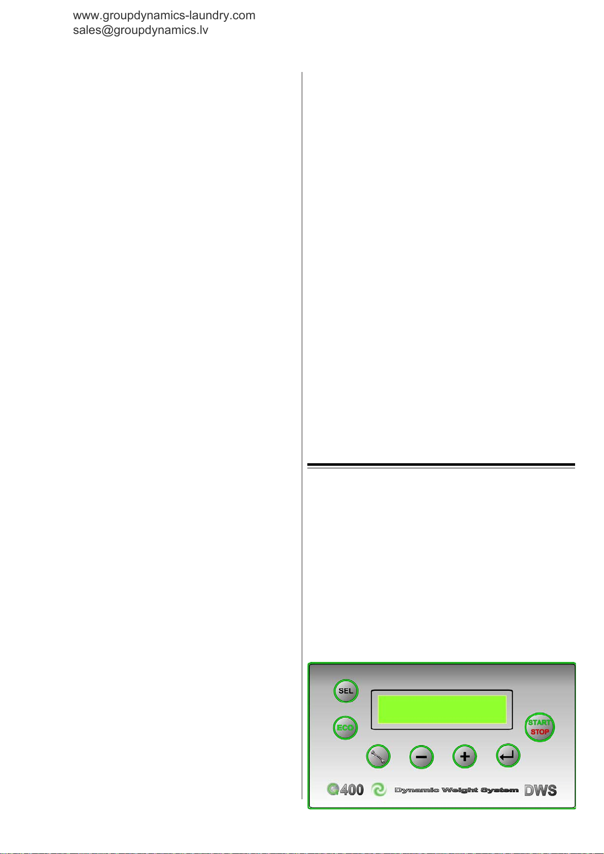
5.2 DESCRIPTION OF THE KEYPAD
4.7 STEAM CONNECTION (STEAM-HEATED
MACHINES ONLY)
The equipment features a steam inlet for saturated dry steam. Inlet
diameter depends on the machine model (cfr. technical details).
The incoming steam pressure must be comprised between 1 and 6
4

SEL: Cycle (program) selection BUTTON
www.groupdynamics-laundry.com
sales@groupdynamics.lv
ECO: ECONOMY BUTTON: to reduce water consumption by
20%. THIS DOES NOT consider the effective wash load and works
only if the "weighing" function is not featured.
!!
"
! " ENTER BUTTON: to confirm selections when programming
!!
optional parameters.
"+" PLUS PUSH BUTTON: to increase values.
"-" MINUS PUSH BUTTON: to decrease values
If the "+" and " - " buttons are pressed during operation, the machine
is put to pause. To resume operation press the START / STOP
button.
"Key tool" MODE push button: is used to enter and exit the
MACHINE PARAMETER menu and the SERVICE menu.
START / STOP: it is used to start the wash cycle. If it is held down
for longer than 5 seconds it causes the END OF THE CYCLE.
5.3 COMPLETE APPLICATION RANGE
Your washing machine was designed to wash synthetics, woolens,
cottons and linens. Choose your cycle by the appropriate button as
suggested on the labels attached to the garments to be washed.
5.4 ELECTRICAL SYSTEM DETAILS
The built-in electrical system is composed of protection and control
devices duly lodged on a plate in the top part of the machine. The
relevant diagrams and lists appear later on in this manual.
6. WASHER OPERATION
Make sure that the cold water, warm water and steam taps are open
(the latter applies only to steam-heated machines).
Turn ON the automatic overcurrent circuit breaker on the wall. If
the door is closed, the machine will then be ready to be started using
the appropriate button (START/STOP) on the front panel.
To select and start a cycle and also to program optional functions,
refer to the block diagrams later on in this manual.
Make your cycle selection following the temperature and wash
action suggested in the labels attached to the garments (see cycle
description below), sort the laundry according to the type of fabric,
load the drum and close the door.
Then fill the various dispenser bins with soap (foam-damping type)
according to cycle selection, i.e.:
A prewash compartment (when scheduled in the selected wash
cycle)
B main wash compartment
C compartment for optional conditioning agent (when scheduled
in the selected wash cycle)
D compartment for optional conditioning agent (when scheduled
in the selected wash cycle)
E compartment for optional conditioning agent (when scheduled
in the selected wash cycle)
ECONOMY FUNCTION WARNING:
This function simply reduces the amount of water and soap used
with reference to factory-foreseen amounts. NOT to be interpreted
as "half-load button".
To start the cycle, press the START / STOP push button with the
door closed: The door will automatically be locked. Cycle progress
will be shown on the control panel display unit.
Pressure on the START / STOP button also causes the timer to
commence the countdown to the end of the cycle.
Such time values are those that the machine has stored in a previous
equivalent cycles. Therefore they are not binding but represent a
mere reference.
6.1 FAST-FORWARDING AND END OF CYCLE
When a wash cycle is in progress, each pulse on the START / STOP
causes the cycle to move one step forward. If the same button is held
down for more than 5 seconds, the cycle will move straight to the
end, which will consequently cause the door to unlock.
Each time a button is pressed the machine beeps briefly. It beeps for
15 seconds at the end of the cycle.
It is however possible to stop the beeper by pressing the " - " push
button or even inhibit the beeper altogether through programming.
6.2 ALARM AND FAULT SIGNALING
When faults arise (voltage drop, supertemperature, water level
error in the drum) the equipment notifies the user by a number of
alarms that appear on the front panel DISPLAY. All alarm details
are dealt with in the "SAFETY MEASURES" chapter.
6.3 CYCLE STEPS
The control display reads the various steps, i.e.:
1) WEIGHING - The machine weighs the laundry. Weighing can
be automatic (standard) or manual. This step can only be
performed at the beginning of the cycle.
2) SOAK - Soak step underway (when scheduled).
3) PREWASH - Prewash step underway (when scheduled)
4) WASH - Wash step underway
5) RINSE - This message is read when the machine is performing
any rinsing step in the cycle.
6) SPIN - Final or intermediate spin underway
7) DISTRIBUTION - Distribution step underway
At any rate, every step is read along with a description explains the
relevant details.
When the end of the cycle is reached, the door is automatically
unlocked: then it will be possible to open the door using the handle
and pick the clean laundry.
CAUTION! Never force the door open. Open by hand only after it
has been unlocked.
At any rate, before opening the door make sure that the drum has
stopped, the water has been drained and the temperature inside the
drum is below 40°C .
Should a potential drop occur during the wash cycle, it will be
possible to open the door after about 90 sec.; in case of emergency
or defect of the door-opening device, to open the door jerk the
manual puller downwards (see fig. 2).
To reach the manual puller it is necessary to unscrew the two fixing
screws with a cross-bit screwdriver and withdraw the machine's
lower front panel. After the door has been unlocked manually, open
it using the handle as explained above and then put the panel back
in place.
6.4 CONFIGURATION OF SETTINGS
Besides the "START/STOP" and the "ECO" push-buttons, the
machine has 4 more buttons for cycle selection and special functions.
More precisely, with the door closed and before starting a cycle, the
programming mode can be entered by pressing the "MODE" pushbutton.
For further details cfr. the block-diagram attached.
WARNING: if a potential drop should occur during a programming
session, changes will not be saved and it will be necessary to repeat
the programming procedure from the beginning.
6.5 PROGRAMMIMG BY PC - OPTIONAL
Washers can also be programmed via PC through a serial port. To
this purpose the washers feature an ad-hoc RS232 serial port at the
rear (OPTIONAL).
To enable the "data transmission and reading" mode it will be
necessary to switch the washer on while holding down the "MODE"
key: the displays will read "HOST COMPUTER" only.
For further details, contact your seller or the after-sales service.
CAUTION!
Do not try to read or change machine programming, unless you
have the ad-hoc cable supplied by the manufacturer, as this could
cause severe damage to the electronic boards.
If you wish to change machine programming, contact your seller or
the after-sales service.
6.6 PROGRAMMIMG BY SMART CARD
Washers can also be programmed using a SMART CARD. As a
matter of fact, the Smart Card reader featured as standard can save
or load the machine-control firmware.
5
6.6.1 WASH PROGRAMS
www.groupdynamics-laundry.com
sales@groupdynamics.lv
Wash cycles can only be saved and loaded (as preset) when the
machine is on, no cycle is in progress and the door is open. On
inserting the Smart Card the G400 control identifies the card:
a) Invalid card: the display will read "invalid card": remove the
card. As soon as it is removed the machine will resume
standard readings.
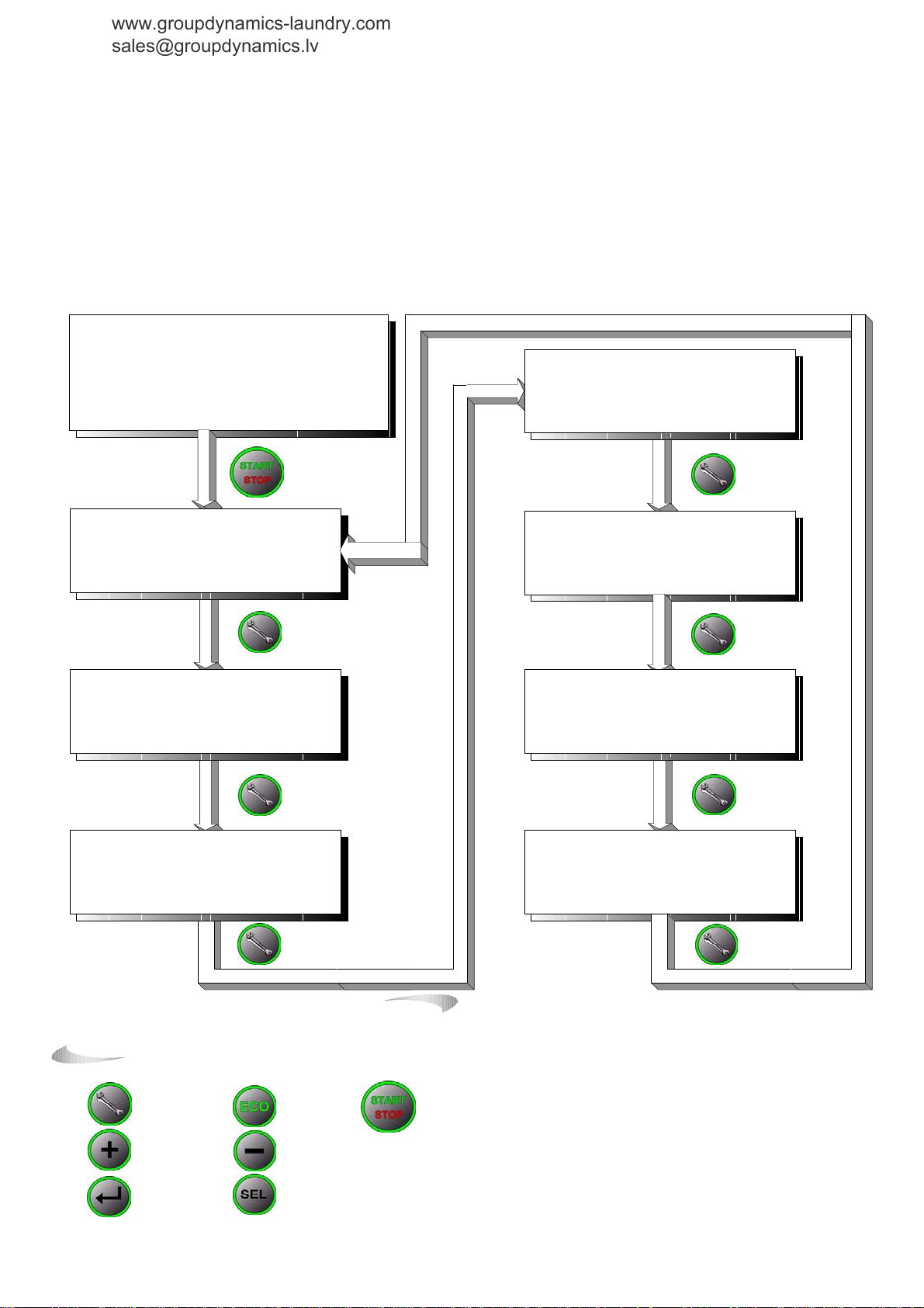
CYCLE SELECTION, VIEW AND START
b) Firmware card: the display will read "software card" and will
allow no action other than removing the card.
c) Correct card: the display will read "cycles card" and will offer
the user two graphic options: download the programs to the
G400 or upload them to the Smart Card. Make your selection
using the "+" and " - " keys and confirm by the key "! :
ENTER".
MACHINE AWAITS START
DISPLAY READING:
`
Program selection from P01 to P20
`
Time to cycle end: clock icon and time in hh:mm
`
Maximum temperature in the cycle
`
Cycle name
`
Door status: open or
CYCLE IN PROGRESS
DISPLAY READING:
` Program selection flashes for the first 2 minutes
` Time to end of cycle: clock icon and time countdown alternate with
name of step
` Water intake icon if applicable
` Number and name of step in progress
CYCLE IN PROGRESS
DISPLAY READING:
` Water intake icon if applicable
` Number and name of step in progress
` Temperature setting and effective temperature
` Water level setting and effective temperature
` Number of water liters taken in. OPTIONAL
CYCLE IN PROGRESS
DISPLAY READING:
` Water intake icon if applicable.
` Number and name of step in progress
`
W
arm water intake enabled YES/NO and number of liters taken in
`
Cold
water intake enabled YES/NO and number of liters taken in
`
Cold
water intake enabled YES/NO and number of liters taken in
closed
Programming and Menus
Push buttons
MODE
button
PLUS
button
ENTER
button
ECONOMY
MINUS
CYCLE
SELECTION
button
button
button
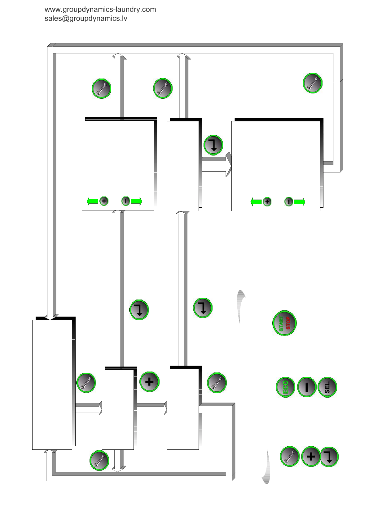
CYCLE IN PROGRESS
DISPLAY READING:
` Water intake icon if applicable
`
Number and name of step in progress.
`
Dispenser A: dispenser ON time
`
Dispenser B: dispenser ON time
`
Dispenser C: dispenser ON time
CYCLE IN PROGRESS
DISPLAY READING:
` Water intake icon if applicable
` Number and name of step in progress
`
Soap pump n°1: pump ON time
`
Soap pump n°2: pump ON time
- - - - - -
`
Soap pump n°9: pump ON time
CYCLE IN PROGRESS
DISPLAY READING:
` Water intake icon if applicable
` Number and name of step in progress
`
Motor action: to left and time countdown
`
Motor action PAUSE and time countdown
`
Motor action: to right and time countdown
`
Motor speed in RPM
CYCLE IN PROGRESS
DISPLAY READING:
` Water intake icon if applicable
` Number and name of step in progress
` Drainage delay: YES / NO
` Drain at end of step: YES/ NO
CYCLE
START/STOP
button
8
www.groupdynamics-laundry.com
sales@groupdynamics.lv
MACHINE STANDBY STATUS
MACHINE PARAMETERS
COOLING CHANGE
OVERRIDE SPINNING
OVERRIDE PREWASH CYCLE DEFERRED START
ENABLE /DISABLE BUZZER
REDUCED HEATING
DRUM ROTATION HEATING HYSTERESIS
STRUCTURE OF MENUES
VIEW COUNTDOWN TIME
START WITH H2O
ENABLE SOAP PUMPS
AUTOMATIC TARE AND LEVEL CALIBRATION
ENABLE CYCLES
MACHINE STANDBY STATUS
SERVICE EN TER PASSWORD:_ _ _ _ _ _
SEQUENCE OF BUTTONS
MACHINE STANDBY STATUS
SERVICE MENU
LANGUAGE
DEGREE TYPE SPINNING MOTOR (2° LEVEL) WEIGHT CONVERSION FACTOR (2° LIVELLO)
DRAIN TIME STANDARD WATER INTAKE
BALANCED WATER INTAKE
H2O TIME-OUT
ECONOMY FUNCTION
HEATING TABLE
MACHINE TYPE ELECTRONIC COIN-OP SETTINGS (2° LEVEL) PASSWORD
CONSUMPTION MAINTENANCE (2°LEVEL)
COMMENTS MACHINE BLOCKED
MACHINE TESTING
7
button
CYCLE
START/STOP
MACHINE ON AWAITS CYCLE START
DISPLAY READINGS:
closed
Program selection from P01 to P20
Time to the end of the cycle
Maximum temperature in the cycle
Cycle name (max 20 chars.i)
Door status:
`
`
`
`
`
MACHINE STANDBY STATUS
Programming
MACHINE PARAMETERS
MACHINE STANDBY STATUS
Programming
SERVICE MENU
ECONOMY
button
button
MINUS
button
CYCLE
selection
Push buttons
Programming and menus
MODE button
PLUS button
ENTER button

6.6.2 FIRMWARE
www.groupdynamics-laundry.com
sales@groupdynamics.lv
To save and load the firmware, insert the Smart Card when the
machine is off. When the machine is then turned on the system will
react by showing the following messages:
a) Invalid card: the display will read "invalid card": remove the
card. As soon as it is removed the machine will resume
standard readings. At this stage also the cycles card will be
considered invalid.
b) Correct card: the display will read "software card" and will
graphically inform the user that the firmware is being transferred
from the Smart Card to the G400 (firmware upgrade): Loading
the firmware from the G4 controller to the Smart Card is not
possible.
If a software card is inserted when the machine is on, the G400
control will start the card identification routine and will allow no
further action.
CAUTION!
Do not attempt to read or program the machine using SMART
CARDS other than the original one (ATM cards, credit cards, other
service cards etc.) as they will be irretrievably damaged. The
manufacturer undertakes no liability for incorrect or improper use
of the Smart Card reader on the machine.
If you need to change machine programming by this system,
contact your seller or the after-sales service.
6.7 USEFUL ADVICE
Remember that loading 80% of the rated capacity provides better
wash results.
Mind that more soap does not mean cleaner: on the contrary, using
too much washing agents leads only to unnecessary pollution. The
right amount of soap is indicated by the manufacturer according to
the hardness of the water used.
Unless specifically advised against, the use of the reduced water
and temperature cycles is warmly recommended, in order to cut
back water and energy consumption and consequently reduce cycle
length.
Before loading the drum make sure that buttons, zips, clasps and
buckles are facing inside Check that the pockets are empty.
At the end of a working day do the following:
- leave the door open;
- turn the machine off by the master switch;
- close the warm water, cold water and steam taps (the latter applies
to steam-heated machines only);
- turn the wall circuit breaker off.
6.8 THE WEIGHING FUNCTION
The washing machine is fitted with a special function that informs
the user how many kilos of laundry he/she has loaded onto the
drum. When this value is available, the machine proportions the
amount of water and detergents to the real load and not to a the
standard theoretical full-load value.
The weighing function is fully automatic: all the user has to do is
load the drum, select the desired program, close the door and push
the "START / STOP" button.
To change the weighting function from automatic to manual it is
necessary to alter the settings using a PC connection and the ad-hoc
software. Contact the technical after-sales service for further
details.
CAUTION! When the machine performs the weighing function
automatically, the weight value read NEVER appears on the
display. This occurs only when the weighing function is manual.
6.9 WASH PROGRAMS
Cycle steps are detailed in the user-friendly tables attached.
Generally speaking, the first 9 cycles feature automatic weighing,
cycle 10 rinses and spins only, and the last 9 cycles are clones of the
first nine cycles except for the weighing function, which is
DISABLED. Cycle 20 is empty (customizable). At any rate, ALL
cycles can be customized using a PC and the ad-hoc software.
Contact the technical after-sales service for further details.
CAUTION!
If the machine has been programmed via PC or optional functions
have been enabled, the cycle tables provided below do not apply.
The manufacturer reserves the right to change cycle the features or
the machine's
6.10 ADVICE
Do not leave the machine on to no purpose. TURN the master switch
OFF when the machine is not being used.
During use:
- Only open the door after the drum has come to a complete stop and
it has been drained.
- In case of a potential drop during a washing cycle, the door may
be opened after about 90 sec. In case of emergency or defect of the
door opening device, it is possible to open the door by jerking the
manual puller downwards (see fig.1). Before opening the door make
sure that the drum has come to a complete stop, that the water has
been drained and that the temperature is below 40°C.
- Before any maintenance or cleaning operation, check that the wall
circuit breaker is off and the warm water, cold water and steam taps
are closed (the latter applies to steam-heated machines only).
- Do not machine-wash fabrics that have been cleaned, dampened,
washed or stain-removed with inflammable or explosive substances.
Otherwise, hand-wash them first.
- Keep inflammable liquids far from the washing machine, in a dry
and ventilated spot, out of the reach of outsiders.
- Keep cleaning products and washing powder far from the
equipment. If possible, keep them closed in a cabinet.
- Do not hamper air inlets or heat-exchanging openings. Keep an
appropriate distance between the machine and the walls or other
objects.
7. SAFETY PROCEDURES
During operation, the machine monitors working conditions and,
in case of malfunction, displays the relevant alarm signals.
Such signals will flash on the display.
When alarms arise, some of them can be removed by switching the
machine off and then on again. These removable alarms also cause
the door to be unlocked, although 90 seconds after the alarm occurs.
To remove the alarm signal from the display unit, either switch the
machine off and then on again (to disconnect and reconnect the
card) or wait for 5 minutes: the alarm will be called off automatically
(see the specific alarm management section).
Of course, if the cause for the alarm persists, the alarm signal will
be there again even after switching the machine back on or after the
automatic reset caused by program restart (the user must press the
START/STOP push button).
7.1 PARTICULAR FEATURES OF THE "MOTOR
FAILURE" ALARM
For some alarm types involving the inverter / motor, reset may occur
automatically.
Then when an inverter alarm arises, the motor goes to idle for 90
seconds (8kg model), 120 seconds (11kg model), or 150 seconds
(18kg model). The inverter too stays "idle" during that time.
After the time indicated the machine resumes operation from the
step right after the one in which the alarm occurred.
This procedure can be repeated for 5 times maximum. Then the
program is aborted and the door is unlocked after a further 150 sec
safety time.
The alarm will stay on in the display for 300 secs. Then the machine
will reset automatically, and will be ready and waiting for a new
start to be given.
The buzzer only trips when the program is interrupted. The only
notice given all through the attempts at finishing the programmed
step is the alarm signal on the display.
8

PARAMETER CONFIGURATION
www.groupdynamics-laundry.com
sales@groupdynamics.lv
MACHINE STANDBY STATUS
MACHINE PARAMETERS
1) COOLING
2) SPINNING
3) PREWASH
4) DEFERRED START
5) BUZZER
6) HEATING
7) ENABLE CYCLES
. . . . . . .
. . . . . . . .
MACHINE PARAMETERS
1) COOLING
MACHINE PARAMETERS
2) SPINNING TIME
MACHINE PARAMETERS
3) PREWASH
MACHINE PARAMETERS
4) DEFERRED START
MACHINE PARAMETERS
5) BUZZER
MACHINE PARAMETERS
6) HEATING
MACHINE PARAMETERS
7) ENABLE CYCLES
MACHINE PARAMETERS
1) COOLING
CYCLE 01
MACHINE PARAMETERS
2) SPINNING TIME
MACHINE PARAMETERS
MACHINE PARAMETERS
4) DEFERRED START: disabled /
enabled
WHEN ENABLED, DELAY TERM CAN
BE SET.
DELAY RANGE: 00h:00min - 23h:59min
TIME STEP: 1 MINUTE
MACHINE PARAMETERS
MACHINE PARAMETERS
6) HEATING:
normal / reduced
MACHINE PARAMETERS
7) ENABLE CYCLES
CYCLE 01
CYCLE 02
CYCLE 03
. . . . .
CYCLE 20
CYCLE 02
CYCLE 03
. . . . .
CYCLE 20
CYCLE 01
CYCLE 02
CYCLE 03
. . . . .
CYCLE 20
3) PREWASH
CYCLE 01
CYCLE 02
CYCLE 03
. . . . .
CYCLE 20
5) BUZZER: YES / NO
MACHINE PARAMETERS
MACHINE PARAMETERS
1) COOLING
. . . . . .
CYCLE 02: YES / NO
. . . . . .
MACHINE PARAMETERS
2) SPINNING TIME
. . . . . .
CYCLE 03: 0 - 150%
. . . . . .
MACHINE PARAMETERS
3) PREWASH
. . . . . .
CYCLE 02: YES / NO
. . . . . .
MACHINE PARAMETERS
7) ENABLE CYCLES
. . . . . .
CYCLE 02: YES / NO
. . . . . .
9

MACHINE STANDBY STATUS
www.groupdynamics-laundry.com
sales@groupdynamics.lv
MACHINE PARAMETERS
. . . . . . .
8) DRUM MOVEMENT INTAKE/DRAIN
9) HEATING HYSTERESIS
10) PUMP LEVEL
11) START WITH H2O
12) CALIBRATION
13) VIEW CYCLE TIME
MACHINE PARAMETERS
8) DRUM MOVEMENT INTAKE/DRAIN
MACHINE PARAMETERS
9) HEATING HYSTERESIS
MACHINE PARAMETERS
10 ) PUMP LEVEL
MACHINE PARAMETERS
11) START WITH H2O
MACHINE PARAMETERS
12) CALIBRATION
MACHINE PARAMETERS
13) DISPLAY CYCLE TIME
MACHINE PARAMETERS
MACHINE PARAMETERS
8) DRUM MOVEMENT
INTAKE/DRAIN
CYCLE 01
CYCLE 02
CYCLE 03
CYCLE 20
MACHINE PARAMETERS
9) HEATING HYSTERESIS
RANGE BETWEEN 2°C AND 6°C
MACHINE PARAMETERS
10) PUMP LEVEL
PROGRAMMABLE FROM MIN.
THRESHOLD OF 4CM
MACHINE PARAMETERS
11) START WITH H2O
12) CALIBRATION
CLOSE DOOR AND PRESS START / STOP
THAT STARTS AUTOMATIC PROCEDURE
. . . . .
CYCLE 01
CYCLE 02
CYCLE 03
. . . . .
CYCLE 20
MACHINE PARAMETERS
8) DRUM MOVEMENT INTAKE/DRAIN
. . . . . .
CYCLE 02: YES / NO
. . . . . .
MACHINE PARAMETERS
11) START WITH H2O
. . . . . .
CYCLE 02: SI / NO
. . . . . .
WAIT FOR END
OF STEP
MACHINE
WAITS FOR
START
MACHINE PARAMETERS
13) DISPLAY CYCLE TIME
CYCLE 01
CYCLE 02
CYCLE 03
….CYCLE 20
MACHINE PARAMETERS
13) DISPLAY CYCLE TIME
. . . . . .
CYCLE 03: - - h: - - min.
PROGRAMMING RANGE BETWEEN 00h :
00min AND 99h : 59min
10

ALARM E1 WATER IN THE TUB
f
www.groupdynamics-laundry.com
sales@groupdynamics.lv
DISPLAY DESCRIPTION E1: WATER IN THE TUB
DESCRIPTION
BUZZER The BUZZER will not go on.
ALARM RESET
CHECKS REQUIRED
CORRECTIVE ACTION
ALARM E2 WATER INTAKE TIME EXCEEDED
DISPLAY DESCRIPTION
DESCRIPTION
BUZZER
ALARM RESET
CHECKS REQUIRED
CORRECTIVE ACTION
ALARM E3 WATER DRAIN TIME EXCEEDED
DISPLAY DESCRIPTION
DESCRIPTION
BUZZER The BUZZER will not go on.
ALARM RESET
CHECKS REQUIRED
CORRECTIVE ACTION
If the pressure switch detects a water level above 4cm
at the beginning of the cycle, this will be terminated.
The alarm can be removed by switching the machine
off and then on again.
drain condition
leve l pre ssur e-s witc h
condition of tub/pressure switch tube
Clean and inspect the drain valve.
Perform level calibration for the electronic card.
Replace the tube connecting the tub to the pressure
switch.
E2: poor water level
During a wash cycle the water failed to reach the
required level in the programmed intake time; water
intake and the wash cycle will proceed normally.
The buzzer will go on only 5 minutes after the alarm
occurred.
The alarm is automatically dismissed if the required
water level is reached in 5 minutes.
The machine will prompt the user whether to restart
the cycle or not: “START:?” if the machine failed to
reach the required level in 5 minutes.
drain condition
leve l pre ssur e switch
condition of tub/pressure switch tube
Clean and inspect the drain valve and the water intake
valves.
Perform level calibration for the electronic card.
Replace the tube connecting the tub to the pressure
switch.
E3: drainage failure
During a wash cycle, 1minute after the start o
draining the water level failed t o drop under the
minimum threshold (4cm); water draining and the wash
cycle proceed normally.
The alarm is automatically dismissed as soon as the
water level drops below the 4cm minimum threshold.
drain co ndition
leve l pre ssur e switch
cond ition of tub/p ressure swit ch tube
Clean and inspect the drain valve and the water intake
valves.
Perform level calibration for the electronic card.
Replace the tube connecting the tub to the pressure
switch.
ALARM E4 HEATING TIME EXCEEDED
DISPLAY DESCRIPTION
E4: slow heating
After the heating has worked for 20 minutes, the
DESCRIPTION
temperature failed to rise by at least X°C. The display
reads “E4: slow heating", and the cycle proceeds
normally.
BUZZER The BUZZER will not go on.
The alarm is automatically removed as soon as the
ALARM RESET
calculated threshold or the maintain (soak) time is
reached.
drain condition
CHECKS REQUIRED
level pressure swit ch
condition of tub/pressure switch tube
Condition and cleanliness of heating elements
Clean and inspect the drain valve and the water intake
valves.
Perform level calibration for the electr onic card.
CORRECTIVE ACTION
ALARM E5
DISPLAY DESCRIPTION
DESCRIPTION
BUZZER The BUZZER goes on immediately.
ALARM RESET
CHECKS REQUIRED
CORRECTIVE ACTION
ALARM E5
DISPLAY DESCRIPTION
DESCRIPTION
ALARM E6 DOOR LOCK/UNLOCK TIME EXPIRED
DISPLAY DESCRIPTION
DESCRIPTION
BUZZER The BUZZER will not go on.
ALARM RESET
CHECKS REQUIRED
CORRECTIVE ACTION
ALARM E7 DOOR FAULT ALARM
DISPLAY DESCRIPTION
DESCRIPTION
BUZZER The BUZZER goes on.
ALARM RESET
CHECKS REQUIRED
CORRECTIVE ACTION
Replace the tube connecting the tub to the pressure
switch.
Replace the faulty heating elements.
Ensure that the value entered in the SERVICE menu,
item “HEATING TIME: X°C/20minutes”, is
correct.
SUPERHEATING OR DISCONNECTED
SENSOR
E5: superheating - probe 1
At any given moment if sensor TEMP1 is not
connected or if it reads a temperature above
below 0°C,
The alarm can be removed by switching the machine
off and then on again.
Perfect condition of temperature probe: cable + sensing
element + connector.
Correct connection of the electronic card
Proper operation of heating contactor
Condition and cleanliness of heating elements
Replace the broken element with a new one.
Correct connection of the electronic card
Replace the heating contactor with a new one
Replace the faulty heating element/s.
SUPERHEATING OR DISCONNECTED
SENSOR
E5: superheating probe 2
SEE PREVIOUS ALARM: This alarm is enabled for
spe cial ve rsio ns.
E6: door failed to be locked/unlocked
If the door is not locked/unlocked within 10seconds
from the door lock/unlock command, this is
interrupted.
The alarm is removed by holding the START / STOP
button pressed until the door can be opened manually
using the procedures specific to each machine model.
The do or may have been closed incorrectly by hand.
The handle may have been forced: the lock
microswitch o r lock devices may have been damaged.
Open and close the door again and start the cycle.
Replace the faulty microswitch/es or the entire door
lock.
E7: Door fault
If there is a power drop affecting the door microswitch
MPORT or at the door-lock signal input MBLOC, the
cycle in progress is interrupted.
The machine will prompt the user whether to restart
the cycle or not: “START:?”.
If the problem persists, it will be necessary to switch
the machine off and then on again.
The handle may have been forced during the wash
cycle: the lock microswitch or lock devices may have
been damaged.
Replace the faulty microswitch/es or the entire door
lock.
the cycle will automatically be terminated.
95°C or
11

ALARM E8 LEVEL ERROR
f
www.groupdynamics-laundry.com
sales@groupdynamics.lv
DISPLAY DESCRIPTION
DESCRIPTION
E8: Level error
If a water level 10 cm above the established height is
detected, the cycle is interrupted.
BUZZER The BUZZER goes on.
When the level is back below the safet y value t he
display prompts “START ?”. The user can either try to
ALARM RESET
resume the program from same step or go to the end o
the cycle and collect the washing. The alarm can also
be removed by switching the machine off and then on
again.
working conditio n of the w ate r intake valves
CHECKS REQUIRED
leve l pressur e switch
condition of tub/pressure switch tube
Clean and inspect the water intake valves
Perform level calibration for the electr onic card
CORRECTIVE ACTION
Replace the tube connecting the tub to the pressure
switch
DO not use very foamy soap.
ALARM E9 OUT-OF-BALANCE
DISPLAY DESCRIPTION
E9: Out of balance
The tilt switch (the contact connected to MSBIL
opens) notifies that there is a mechanical hazard
involving drum movement and the weight distribution
DESCRIPTION
inside the drum. This alarm is monitored only during
spinning and weighing. The alarm appears on the
display only after the last restart attempt has failed, and
then the cycle is terminated.
BUZZER The BUZZER goes on.
ALARM RESET
This alarm is reset at the end o f the step in which it
occurred, and the door is simultaneously unlocked.
Cor rect adjustment of the tilt switch.
Correct positioning of the microswitch rod in the
mobile window.
CHECKS REQUIRED
The laundry load needs to be as homogeneous as
possible.
Vibration dampers and shock absorbers must be in
goo d condition. They must not be discharged or worn
down.
Connect t he tilt switch properly.
Position the microswitch rod properly inside the mobile
CORRECTIVE ACTION
window.
Optimize the laundry load.
Replace discharged or worn down vibration dampers
and shock absorbers.
OUT OF BALANCE OUT OF BALANCE “A”, “B” or “C”
DISPLAY DESCRIPTION
DESCRIPTION
“A”, “B” or “C” flashing on the second screen of the
spinning step (pushing the MODE button). This
reading is not available for SELFSERVICE versions.
While in the speed = distribution 1, the machine assesses
the distribution quality inside the drum, i.e. how the
laundry items are distributed.
Letter “C” stands for good distribution, letter “B” stands
for mediocre distribution, and letter “A” stands for bad
distribution.
When distribution is assessed to be type “A” final spinning
speed will automatically be reduced by 7.5%.
If distribution is type “B” or “C” maximum sp inning
speed remains unchanged.
BUZZER The B UZZER will not go on.
ALARM RESET
CHECKS REQUIRED
CORRECTIVE ACTION
AUTOMA TIC SPEED
REDUCTION
DISPLAY DESCRIPTION
DESCRIPTION
BUZZER The BUZZER will not go on.
ALARM RESET
CHECKS REQUIRED
CORRECTIVE ACTION
ALARM
This function is automatically enabled and disabled at each
spinning step.
If distribution type “C” occurs often, check that the
laundry load is as equalized as possible.
Vibration dampers and shock absorbers must be in good
condition. They must not be run down or worn out.
As a rule no corrective action is needed, other than
equalizing the laundry loa d (using it ems similar in size and
type).
LAUNDRY LOAD TOO BIG OR TOO SMALL
NONE
IF THE AUTOMATIC WEIGHING FUNCTION
HAS BEEN ENABLED, the machine weighs how heavy
the laundry load contained in the drum is, ex pressing it in
kilos.
If the drum is UNDERLOADED, i.e. the load is 40%
smaller than the rated capacity, or else if the drum is
OVERLOADED, meaning that the load is in excess of
120%, the maximum spinning speed is automatically
reduced by 8% in models for 22kg, it is reduced by 15%
in models for 1 6.5kg and by 10% in models for 7, 4kg and
9,5kg.
This function is automatically enabled and disabled at each
spinning step.
Check that the laundry load at issue falls within the
machine's working range.
As a rule no corrective action is needed, other than
equalizing the laundr y load (using items similar in size and
type), and using a load between 40% and 120% of the
machine's capacity rating.
MOTOR OVERLOAD SWITCH TRIPPED WITH
AUTORESET ALARMS
EF Motor fault
1 “
”
2 “OC Motor overcurrent”
DISPLAY DESCRIPTION
3 “OV motor overvoltage”
UV motor undervoltage
4 “
5 “OCH motor failure”
6 “ST motor failure”
These 6 alarms are read on the display. The listing
DESCRIPTION
priority is from highest to lowest. When in error
condition, the inverter awaits the automatic reset of the
G400 control.
BUZZER The BUZZER goes on.
Control G400 performs the first reset attempt and the
display prompts “START?”.
ALARM RESET
After 5 consecutive attempts the alarm stays fixed and
can only be removed by switching the machine o ff and
then on again.
The power voltage supplied to the machine must be in
CHECKS REQUIRED
the range specified in the rating plate.
The wash load MUST NOT exceed the machine’s
rated load.
Connect the appliance to a power source ensuring the
CORRECTIVE ACTION
correct voltage.
Optimize the laundry load.
”
12

ALARM
www.groupdynamics-laundry.com
sales@groupdynamics.lv
DISPLAY DESCRIPTION
DESCRIPTION
BUZZER The BUZZER goes on.
ALARM RESET
CHECKS REQUIRED
CORRECTIVE ACTION
MOTOR OVERLOAD SWITCH TRIPPED WITH
NON AUTORESET ALARMS
1 “OH inverter supertemperature”
OLi inverter overload
2 “
3 “OLM motor overload”
OLR brake overload
4 “
5 “OT motor torque overload”
inverter phase failure
6 “PH
7 “FU inverter input fuse”
OP1 communication failure
8 “
9 “OP2 communication failure”
communication failure
10 “BF
11 “OHS inverter supertemperature”
LF Inverter limit condition
12 “
13 “SHC mo tor short circuit”
These 13 alarms are read on the display as they occur
and their listing priority is the same.
There is NO inverter autoreset time.
The alarm is fixed and can only be removed by
switching the machine off and then on again. The
display will read the relevant alarm acronym and will
prompt the user to “switch off the machine”.
CAUTION! Many causes may need to be attended to
by the service personnel.
“OH inverter supertemperat ure”:
1
installation needs to meet the rating plate details.
Check that the inverter fans are clean and in good
working condition.
2 “OLi inverter overload”: Optimize the laundry
load.
3 “OLM motor overload”: Optimize the laundry
load.
4 “OLR brake overload”: Optimize the laundry load.
motor torque overload”:
5 “OT
load.
inverter phase failure”:
6 “PH
wiring.
FU Inverter input fuse
7 “
service.
communication failure”:
8 “OP1
sales service.
communication failure”:
9 “OP2
sales service.
BF communication failure
10 “
sales service.
11“ OHS inverter supertemperature” The place of
installation needs to meet the rating plate details.
Check that the inverter fans are clean and in good
working condition.
12 “12 “LF Inverter limit condition” Optimize the
laundry load.
13 “SHC mo tor short circuit” Contact the after-sales
service.
”
”
”
”
”
”
The place of
Optimize the laundry
Restore proper
”: contact the area technical
Contact the after-
Contact the after-
”: Contact the after-
INSTRUCTIONS FOR MAINTENANCE
8. INFORMATION ON SPECIAL USE AND
SAFETY MEASURES
When carrying out the first cycle, verify the following:
- Soap dispensers must stay clean.
- Perform a 90°C cycle to remove all manufacturing residues.
- The operator must be able to check soap compartments with ease.
Place a platform if necessary.
- Make certain that laundry trolleys are lower than the door's bottom
edge.
- If need be, mount appropriate bumpers to prevent trolleys from
impacting and damaging the door.
- Never open the soap compartment when the machine is being
filled with water or it is heating. Some models are standard-fitted
with a device that puts the machine to pause at once. Close the
dispenser and press the START button to begin the cycle again.
8.1 ORDINARY MAINTENANCE BY THE USER
BEFORE ANY MAINTENANCE OPERATION, CHECK THAT
THE WALL CIRCUIT BREAKER IS OFF AND THE WATER
TAPS ARE CLOSED. THE DRUM MUST BE MOTIONLESS
AND DRAINED AND THE TEMPERATURE INSIDE IT MUST
NOT EXCEED 40°C.
The machine requires no special maintenance, thanks to its
ergonomic design and to the use of very reliable, first-quality parts.
Periodically clean the external panels with a damp cloth. Never use
inflammable or abrasive products and rub in the direction of the
satin-finish.
Always keep forced-cooling slots and openings free from dust (the
fan sucks fresh air from the room), which are on the rear of the
machine, where the speed inverter is housed.
NEVER WASH THE APPLIANCE USING WATER JETS.
PRIOR TO CONNECTING POWER SUPPLY AGAIN BY THE
MAIN CIRCUIT BREAKER ON THE WALL, PUT ALL THE
PANELS REMOVED BACK IN PLACE.
8.2 EXTRAORDINARY MAINTENANCE AND
ORDERING SPARE PARTS
8.2.1 ACCESSING THE ELECTRICAL BOARD
Models for up to 22kg
To reach the electrical parts of the machine, take off the screws
fastening the soap dispenser and proceed as follows:
A) Key-locked cover : insert the keys supplied into the two locks
located at the top's rear.
Unlock the cover's front and lift it until it can be held up by the stop
rod located on the side of the machine, beside the soap dispenser.
The cover is hinged at the back of the machine and cannot be
removed altogether.
B) Cover without key-lock: take off the screws fastening the cover
to the back panel; then lift the rear part of the cover and pull it to
the front by approximately 5 cm.
7.2 MANAGEMENT OF ALARM RECORDS
The alarm records will be managed in the SERVICE, menu,
protected by a password of level 1. It will be possible to track the last
10 alarm events recorded by the G400 control. Enter this parameter
to view the sequence with the previous 10 errors, starting from the
very last, along with the step and cycle they occurred in. If the error
occurred astride two steps, the reference will be the earliest step.
Event time and date will not be stored.
Models for over 22 kg
The electrical panel has two parts: the front, which includes control
devices, and the rear, which contains the power devices and the
inverter.
A) Key-locked front cover: insert the keys supplied in the two locks
located on the machine's front and turn this downwards until it
stops against the horizontal support.
B) Cover without key-lock: remove the screws that fasten it to the
back panel and remove the rear to access the power components.
PRIOR TO CONNECTING POWER SUPPLY AGAIN BY THE
MAIN CIRCUIT BREAKER ON THE WALL, PUT ALL THE
PANELS REMOVED BACK IN PLACE.
13

8.2.2 SAFETY DEVICES
www.groupdynamics-laundry.com
sales@groupdynamics.lv
- Door closed safety microswitch cuts off power to the whole
auxiliary circuit and consequently stops the machine.
- Electronic overcurrent device (overload cutout) within the motor:
disconnects power supply in the event of coil overheating.
- Air-break system in the soap dispenser: prevents wastewater from
polluting the drinkable water system in the event of a depression.
- Normally open drain valve: enables safe door manual opening by
means of the manual puller.
- Tilt switch: avoids mechanical damage in the event of irregular
loads.
- Fuse-fitted heating elements. the electric circuit is disconnected in
case of malfunction.
8.3 PERIODIC MAINTENANCE BY TECHNICAL
PERSONNEL
All periodic maintenance operations must be carried out by the
authorized after-sales service or by qualified personnel.
BEFORE ANY MAINTENANCE OPERATION, CHECK THAT
THE WALL CIRCUIT BREAKER IS OFF AND THE WARM
WATER, COLD WATER AND STEAM TAPS ARE CLOSED
(THE LATTER APPLIES TO STEAM-HEATED MACHINES
ONLY). THE DRUM MUST BE MOTIONLESS AND DRAINED
AND THE INSIDE TEMPERATURE MUST NOT EXCEED
40°C.
Be very careful during maintenance. NEVER override or ignore
safety devices for any reason. Use only original spare parts. If doubts
should arise, contact your sales person immediately, explaining
what the fault is and indicating some information on the machine:
model and serial number (details reported on the rating plate
appearing on the rear of the machine or inside the door, where
applicable).
Monthly checks
Make certain that the filters located on the outer part of the electrical
valves are clean.
Make certain that the steam valve strain is clean (this applies to
steam-heated machines only).
Clean the soap dispenser from any soap remains.
Clean the door gasket and the tub inlet with a cloth. Always keep
forced-cooling slots and openings free from dust (the fan sucks
fresh air from the room), which are on the rear of the machine,
where the speed inverter is housed.
Yearly checks
Make certain that the floor fastening nuts are securely closed (if
applicable).
Check the wear of the belts and replace them if necessary. If more
than one of them is worn out, replace the entire set of belts.
Make sure that the safety devices are working properly (e.g. the lock
microswitch and the tilt microswitch).
Check that the screws for electrical connection are tight on the
contactors and power inlet terminal strip.
Disassemble the drain valve and clean it inside from lint.
Check that the heating elements are in perfect condition and clean
them from scale.
BEFORE TURNING THE MACHINE BACK ON BY THE
CIRCUIT BREAKER, PUT ALL THE PANELS REMOVED
BACK IN PLACE.
8.4 AUTOMATIC MAINTENANCE REQUEST
The machine saves the number of cycles it executes. After 1000
programs the machine will flash a message from cycle 1001
onwards.
More precisely, when starting a new cycle by the START/STOP
button, the machine will enable the buzzer and will flash the writing
" MAINTENANCE REQUIRED" for 10 seconds. Then it will carry
out the selected cycle normally. At every cycle, 50 cycles before
cycle 1000, the display puts out the message "MAINTENANCE IN
50 cycles" to warn the user that maintenance will be required. In this
case the buzzer will not be enabled.
When this message is displayed, request yearly maintenance.
To dismiss this reading and start the 1000 cycle count from scratch,
press the push-button "- " for at least 5 secs with the door closed.
Then the total number of cycles performed will be viewed and, if the
push button "-" is pressed again within 10 seconds, the count will
be set to zero and will be ready to start back again.
Before resetting the G400 control it will be necessary to enter a date
and a text. The control will first read the question "date: 01/01/01".
Move the cursor to the first "0". Increase or decrease the selection
as needed using keys "+" and "-" and confirm using the "! :
ENTER" key. Then the cursor will automatically move to the
second figure of the date ("1"). Proceed accordingly until the date
is complete and then press the "! : ENTER" key. The G400 control
will prompt the word "technician": enter the name of the person
who performed the maintenance.
Press the "SEL" key: the cursor will become bigger so that you can
select the letters using keys "+" and "-". Confirm by the "! :
ENTER" key. The cursor will move to the next position so that you
can select the next letter as above. The control count cannot be reset
unless these two values are entered.
This information will be stored and is available in the SERVICE
menu, MAINTENANCE entry, along with the number of cycles
performed from the last maintenance event and the total number of
cycles carried out.
8.5 IDENTIFYING AND ORDERING SPARE PARTS
To identify the codes of spare parts refer to the exploded drawings
and relevant list. Once you have identified your codes, send a
standard written order to the manufacturer, mentioning clearly
machine model, serial number, feed voltage and frequency and, of
course, including the code and description of the spare part needed.
9. MACHINE DECOMISSIONING,
DISMANTLING AND DISPOSAL
If the equipment is no longer to be used, it is advisable to
decommission it and suitably dispose of the resulting materials,
considering the advice provided in the chapter "Transportation and
installation". Please, for the sake of the environment, sort the
materials in accordance with the waste disposal provisions in force
in your country, so that they can be properly disposed of or recycled.
All the parts composing the machine can be treated as solid urban
waste, except for the metal parts, which yet are not classed among
special waste in most European countries.
9.1 INFORMATION TO USERS
Pursuant to the Italian law 151 that implements Directives 2002/
95/EC, 2002/96/EC and 2003/108/EC concerning the reduction in
the use of hazardous substances in electric and electronic apparatus,
as well as waste disposal
the crossed-out dustbin symbol on the appliance indicates the
product must be disposed of separate from other wastes once it
reaches the end of its life cycle.
The sorting for recycling purposes of this equipment when at the
end of its life cycle is organized and managed by the manufacturer.
Users willing to discard this equipment will have to contact the
manufacturer and comply with the procedures the latter has
established for sorting and recycling the machine at the end of its
life cycle. Adequate pre-sorted waste collection before subsequently
sending the appliance for recycling, treatment and environmentally
compatible disposal helps avoid possible negative effects on the
environment and health and favors the recycling of the materials
making up the appliance. Unlawful disposal of the product by the
user is punishable by the administrative sanctions the laws in force
provide for.
14

SPACE REQUIRED FOR MACHINE INSTALLATION, USE AND MAINTENANCE
www.groupdynamics-laundry.com
sales@groupdynamics.lv
Fig. 1
5
2
3
4
15
16
6
7
22kg
835
1
2
9
11
8
4040
5050
19
18
23
17
12
10
25
21
22
24
14
800
15

MACHINE DESCRIPTION
www.groupdynamics-laundry.com
sales@groupdynamics.lv
16

Cycles 1 to 9 with initial automatic weighing
www.groupdynamics-laundry.com
sales@groupdynamics.lv
Cycles from 10 to 19 are identical to 1 to 9, except for initial automatic weighing, which is disabled.
Cycle 1: very soiled whites
For very soiled hard-wearing laundry
40°C prewash with strong wash action 40°C prewash with gentle wash action
500 rpm short spinning 500 rpm short spinning
90°C main wash with strong wash action 60°C main wash with gentle wash action
500 rpm short spinning Rinse with gentle wash action
Rinse with strong action 500 rpm short spinning
500 rpm short spinning Rinse with gentle wash action
Rinse with strong action 500 rpm short spinning
500 rpm short spinning Rinse with gentle wash action and softener int ake
Rinse with strong wash action and softener intake Short 1000 rpm spinning
Short 1000 rpm spinning
Cycle 2: soiled whites
For very soiled hard-wearing laundry
40°C prewash with strong wash action 40°C prewash with strong wash action
500 rpm short spinning 500 rpm short spinning
60°C main wash with strong wash action 40°C main wash with strong wash action
500 rpm short spinning 500 rpm short spinning
Rinse with strong action Rinse with strong action
500 rpm short spinning 500 rpm short spinning
Rinse with strong action Rinse with strong action
500 rpm short spinning 500 rpm short spinning
Rinse with strong wash action and softener intake Rinse with strong wash action and softener intake
Short 1000 rpm spinning Short 1000 rpm spinning
Cycle 3: soiled coloreds
For colored hard-wearing laundry
For very soiled hard-wearing laundry requiring
Soak
Cycle 8: soak for very soiled items
For very soiled hard-wearing laundry requiring
Cycle 6: terry cloth
For toweling items
Cycle 7: delicate soak
soaking
soaking and high-temperature washing
40°C prewash with strong wash action
500 rpm short spinning 60°C prewash with strong wash action
40°C main wash with strong wash action 500 rpm short spinning
500 rpm short spinning 90°C main wash with strong wash action
Rinse with strong action 500 rpm short spinning
500 rpm short spinning Rinse with strong action
Rinse with strong action 500 rpm short spinning
500 rpm short spinning Rinse with strong action
Rinse with strong wash action and softener intake 500 rpm short spinning
Short 1000 rpm spinning Rinse with strong wash action and softener intake
Cycle 4: delicate coloreds
For colored delicates
Cold prewash with delicate wash action
Soak
Short 1000 rpm spinning
For very soiled hard-wearing laundry requiring
Cycle 9: soak for soiled items
soaking and medium/high temperature washing
25°C main wash with gentle wash action
500 rpm short spinning
Rinse with gentle wash action
Rinse with gentle wash action
Rinse with gentle wash action and softener intake
800 rpm last spinning
Cycle 5: very delicate items
For very delicate items
Cold prewash with delicate wash action
25°C main wash with gentle wash action
Rinse with gentle wash action
Rinse with gentle wash action
Rinse with gentle wash action and softener intake
500 rpm last spinning
Soak
40°C prewash with strong wash action
500 rpm short spinning
90°C main wash with strong wash action
500 rpm short spinning
Rinse with strong action
500 rpm short spinning
Rinse with strong action
500 rpm short spinning
Rinse with strong wash action and softener intake
1000 rpm last spinning
Rinse with strong action
1000 rpm last spinning
Simple rinse followed by spinning
Cycle 10: Rinse and spin
17

TECHNICAL DATA
www.groupdynamics-laundry.com
sales@groupdynamics.lv
MODELLI WFG4 8 11 18 22 WFG4 MODELS
Capacità rapporto
Dimensione cesto
Dimensione oblò Diam. mm 290 290 410 410 Diam. Door opening
Velocità cesto r.p.m. 25÷1000 25÷1000 25÷1000 25÷860 r.p.m. Drum speed
Fattore G 74/300 74/300 91/364 83/310 Factor G
Dimensioni Larg. mm 660 660 830 900 Width Dimensions
Dimensioni
imballo dimensions
Volume m
Peso netto/lordo Kg 235/250 275/300 465/485 740/830 Kg Net/gross weight
Alimentazione Pressione KPa 300/500 (3/5 bar) Pressure Water inlet
idrica
Scarico Diam. pollici 3" 3" 3" 3" inches Drain
Consumo * 79 113 137 153
idrico
Acqua calda Lt./ciclo 18 23 40 45 Lt./cycle Hot water
Alimentazione V/ph/Hz 400/3N/50-60 V/ph/Hz Electric supply
elettrica
Potenza riscaldamento Heating power
Standard KW 6 9 12 18 KW Standard
Optional KW 4.2/9 6/12 6/9 12 KW Optional
Potenza motore KW 0.75 1.5 2.2 3 KW Motor power
Potenza totale KW 6.75 10.5 14.2 21/15 KW Total power
Fusibile A 16-20 20-32 25-40 32-63 A Fuse
Rumorosità dB (A) 55 55 58 70.6 dB (A) Noise
1:10 Kg 7.3 9.5 16.5 22 1:10 Capacity ratio
Diam. mm 530 530 650 750 Diam. Drum size
Prof. mm 330 420 500 498 Depth
Volume dm
3
73 95 165 220
Volume
Prof. mm 690 790 960 1060 Depth
Alt. mm 1070 1140 1295 1430 Height
Larg. mm 750 750 930 975 Width Packing
Prof. mm 850 930 1140 1190 Depth
Alt. mm 1240 1290 1510 1620 Height
3
0.79 0.90 1.59 1.88 m
3
Volume
Diam. pollice 3/4" 3/4" 3/4" 3/4" inch
N° entrate 3 3 3 3 3 N° w. inlets
V/ph/Hz 230/3/50-60 V/ph/Hz
Modello vapore diretto/indiretto Direct/indirect steam model
Diretto KPa 50/ 600 (0,5/6 bar) KPa Direct
Consumo Kg/h 7.2 9.5 16.5 45.8 Kg/h Consumption
Indiretto KPa 300/ 600 (3/6 bar) - KPa Indirect
Consumo Kg/h 8.64 11.4 19.8 - Kg/h Consumption
Entrata vapore Diam. pollice 3/4" inch Steam inlet
Scarico vapore ind. Diam. pollici 3/4" inches Ind. steam outlet
Fusibile A 10 10 10 16 A Fuse
* Ciclo 60°C, senza il prelavaggio e carico ottimale. * 60°C program, without pre-wash at rated capacity.
18

Key to components – Electrical board of models WF8-11-18-22G4
www.groupdynamics-laundry.com
sales@groupdynamics.lv
A power card
B power card
BALANCE tilt microswitch
c liter meter common (optional)
C soap pump power card (optional)
CP (COINPROGRAM) coin-meter programming switch (optional)
CR cycle relay (optional)
CS (COINSW) coin-meter microswitch (optional)
D soap-ozone injecting pump power card (optional)
DOORSW door closed microswitch
DSW 1..8 card setting microswitches
DWM (DISPLACEMENT WATER METER) volume liter meter (optional)
E earth lead connection
E/V electric/steam heating selector (optional)
E1 warm water intake electrical valve – dispenser B
E2 warm water intake electrical valve – tub
E3 hard water intake electrical valve – dispenser C
E4 soft water intake electrical valve – tub
E5 soft water intake electrical valve – dispenser A
E6 hard water intake electrical valve – tub
EC (ENERGY CONTROL) remote energy-management input (optional)
ECM metal identifying coin meter (optional)
EMC FILTER noise filter
EV steam electric valve
F power supply phase connection
F1 primary circuit fuse
F2 secondary circuit fuse
F3 control card fuse
F4 power card fuse
F5 soap pump output fuse
FAN1 inverter additional fan
FRU inverter/frequency variator
HC hard cold water intake meter (optional).
HW warm water intake meter (optional).
IE emergency switch (optional)
IG auxiliary master switch (optional)
K1 heating element contactor
K2 coin-meter coil (optional)
K3 second heating element contactor (22 kg mods only)
LOCK door lock coil
M drum motor
N neutral lead connection
NH (NO HEATING) no heating switch (optional)
O3 (Ozone control) ozone injecting management (optional)
PRS pressure transducer
PS1..9 soap pumps 1 to 9
PT1000 n.1 temperature probe
PT1000 n.2 temperature probe
RT thermal relay (mods 8-11 only)
RV3 display brightness adjustment trimmer
S1 drain electrical valve n°1
S2 water recycling/draining electrical valve n° 2 (optional)
SC soft cold water intake meter (optional).
SCH5 control logic card
SCH6 door lock/unlock card
SCR (SMART CARD READER) removable memory-card reader
SP serial port (optional)
TE timer for contactor K3
Tf fuse
TLS (TANK LIQUID SOAP) soap pump tank management input (optional)
TR transformer, self-transformer
UNLOCK door unlock coil
WM (WATER METER) pulse liter meter (optional)
19

COMPLETE WIRING DIAGRAM MODS. 8-11-18
www.groupdynamics-laundry.com
sales@groupdynamics.lv
20

Hot Water
www.groupdynamics-laundry.com
sales@groupdynamics.lv
Soft cold
Hard cold
Displacement
Water-meter
PT1000 n1
+
+
+
OUT
-
OUT
-
OUT
-
PT1000 n2
Water-meter
Hot Water
Soft cold
Hard cold
RV4
COMPLETE WIRING DIAGRAM MOD. 22- 230V
L1 / R
L2 / S
L3 / T
E
FAN1
230
Vac
CN1
CN3
L1
BLACK
230/3 Vac
OUT
RT
2 3 456 7
12 13 14 15 16 17 18 1911
FRU
PE
L2 L 3
EMC
FILTER
BLACK
BLACK
F1
UV
BLACK
230Vac
8
BLACK
3ph
Coin Program
Balance Switch
Energy Control
Tank Liquid Soap
No Heating
DOORSW
COINSW
LOCKSW
ECM
CN1
CN6
CN7
CN8
CN9
CN10
CN12
SMART
CARD
READER
PRS
WATER LEVEL
CN5
SCH5
CN14
12345678901
RS232C
SP
CN2
RV3
LCD CONTRAST
CN13
CN4CN3
CN16
CN15
RS485
5
9
1
A1
A2
CR
SCH6
CN2
LOCK
UNLOCK
DS1..8
SW1
F3
630mA
1
(16)
0
CN11
VIOLA
OUT
ROSA
GRIGIO
IE
V?
F1
IG
800 mA
11
9
W
BLACK
16Vac
TR
M
F2
SPECIAL
VERSIONS
electronic
voltage
stabilizer
2A
245Vca
IE
800 mA
F1
TR
F5
800 mA
OUT
F
TF TF TF TF TF TF
OUT
N
TF TF TF
K1
TF TF TF
K3
C
K3
RCR
K1
E4
K2EV
E2
E6
E1
E5
E3
TE
E/V
CN5
1
OUT1 OUT2 OUT3
CN4
IN1
CN2
CN3
ABCD
OUT1 - IN2
F4
630mA
1
CN1
( )(16) ( )(16)
CN5
1
CN4
IN2 IN3 IN4
CN2
OUT2 - IN3
S1 S2
CN3
CN1
PS1
PS3
PS2
PS4
PS5
PP PPPPP PP
ROSSO
CN5
OUT3 - IN4
ROSA
GRIGIO
VIOLA
1
CN3
630mA
1
CN1
BIANCO
CN4
F4
630mA
1
CN2
PS7
PS8
PS6
NERO
F4
PS9
O3 CONTROL
MARRONE
CN4
CN2
ROSA
BIANCO
CN5
1
GRIGIO
CN3
F4
630mA
1
CN1
0505_B022_SE_WF22G4_230-3 Completo_v.00
21

Hot Water
www.groupdynamics-laundry.com
sales@groupdynamics.lv
Soft cold
Hard cold
Displacement
Water-meter
PT1000 n1
+
-
+
-
+
-
OUT
OUT
OUT
PT1000 n2
Water-meter
COMPLETE WIRING DIAGRAM MOD. 22 - 400V
L1 / R
L2 / S
L3 / T
N
E
Hot Water
Soft cold
Hard cold
RV4
FAN1
230
Vac
Coin Program
Balance Switch
Energy Control
Tank Liquid Soap
No Heating
DOORSW
COINSW
LOCKSW
ECM
CN1
CN6
CN7
CN8
CN9
CN10
CN12
SMART
CARD
READER
PRS
WATER LEVEL
CN5
SCH5
CN14
12345678901
RS232C
SP
CN2
RV3
LCD CONTRAST
CN13
CN4CN3
DS1..8
CN16
CN15
RS485
5
9
1
A1
A2
CR
SCH6
CN2
LOCK
UNLOCK
SW1
F3
630mA
1
(16)
0
CN11
VIOLA
OUT
ROSA
GRIGIO
OUT
CN1
CN3
2 3 456 7
12 13 14 15 16 17 18 1911
L2 L3
L1
EMC
FILTER
BLACK
BLACK
400/3 Vca
F1
RT
8
FRU
PE
UV
BLACK
BLACK
BLACK
400Vca
3ph
IE
V?
F1
IG
800 mA
11
9
W
BLACK
16Vac
TR
M
F2
SPECIAL
VERSIONS
electronic
voltage
stabilizer
2A
245Vca
IE
800 mA
F1
TR
F5
800 mA
OUT
F
TF TF TF TF TF TF
OUT
N
K3
K1
TF TF TF TF TF TF
C
K3
RCR
K1
E4
K2EV
E2
E6
E1
E5
E3
TE
E/V
CN5
1
OUT1 OUT2 OUT3
CN4
IN1
CN2
CN3
ABCD
OUT1 - IN2
F4
630mA
1
CN1
( )(16) ( )(16)
CN5
1
CN4
IN2 IN3 IN4
CN2
OUT2 - IN3
S1 S2
CN3
CN1
PS1
PS3
PS2
PS4
PS5
PP PPPPP PP
ROSSO
CN5
1
OUT3 - IN4
ROSA
GRIGIO
VIOLA
CN3
630mA
1
CN1
BIANCO
CN4
F4
630mA
1
CN2
PS7
PS8
PS6
NERO
F4
PS9
O3 CONTROL
MARRONE
CN4
CN2
ROSA
BIANCO
CN5
1
GRIGIO
CN3
F4
630mA
1
CN1
0505_B022_SE_WF22G4_400-3 Completo_v.00
22

www.groupdynamics-laundry.com
sales@groupdynamics.lv
23

TARGHETTA TECNICA, RATING PLATE, PLAQUETTE
www.groupdynamics-laundry.com
sales@groupdynamics.lv
TECHNIQUE, GERÄTESCHILD, PLACA DE CARACTERÍSTICAS
MODELLO
MODEL
NR. MATR.
SERIAL NR.
ALIM. EL.
EL. POWER
POTENZA TOT.
TOTAL INPUT
PRESSIONE VAPORE
STEAM PRESSURE
ATTENZIONE! E' OBBLIGATORIO IL COLLEGAMENTO A TERRA
CAUTION! THE APPLIANCE MUST BE CONNECTED TO EARTH
RIVENDITORE, DISTRIBUTOR,
REVENDEUR, VERTRIEB, VENDEDOR
ASSISTENZA TECNICA, AFTER-SALES SERVICE,
SERVICE APRES-VENTE, KUNDENDIENST,
SERVICIO DE ASISTENCIA TÉCNICA
MODIFICHE SENZA PREAVVISO, CHANGES WITHOUT NOTICE, MODIFICATIONS SANS PRÉAVIS, ÄNDERUNGEN VORBEHALTEN, MODIFICACIONES SIN PREVIO AVISO
 Loading...