

Grand Hall Yn663ng, Yn663lp Owner's Manual
Owner’s Manual
Customer Service Helpline: If you have questions about assembly or grill operation, or if there are damaged or
missing parts when you unpack this unit from the shipping box, call us Monday through Friday at 1-800-752-3085
n
W
ARNING:
All barbecues and carts are designed for outdoor use only!
All barbecues are not intended for commercial use.
n
W
ARNING:
Read this Owner’s Manual carefully and
be sure your gas grill is properly
assembled, installed and maintained.
Failure to follow these instructions
could result in serious bodily injury
and/or property damage. This gas grill
is intended for outdoor use only and is
not intended to be installed in or on
recreational vehicles or boats.
Note to Installer: Leave this Owner’s
Manual with the consumer after delivery
and/or installation.
Note to Consumer: Leave this
Owner’s Manual in a convenient place
for future reference.
P80151009A
RV 041205
America's Barbecue Grill Superstores
Design Certified
Unit approved by
CSA Laboratories under standard
ANSI Z21-58b-2002/CGA 1.6b-2002
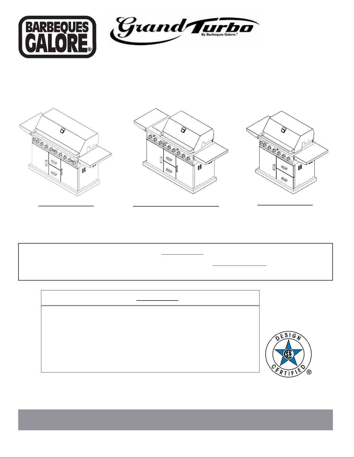
52” All Grill BBQ
YN662AGLP
YN662AGNG
YN662CT
(Cart Only)
38”
All Grill BBQ
YN663LP
YN663NG
YN663CT
(Cart Only)
52” BBQ with Side Burner
YN662LP
YN662NG
YN662CT (Cart Only)
READ THESE SAFETY INSTRUCTIONS
n
WARNING
Fuels used in gas or oil-fired appliances and the products of
combustion of such fuels, contain chemicals known to the
State of California to cause cancer, birth defects and/ or
other reproductive harm.
This warning is issued pursuant to California Health &
Safety Code Sec. 25249.6.
n
WARNING
Failure to comply with these instructions could result in a
fire or explosion that could cause serious bodily injury,
death, or property damage.
n
WARNING
Your grill will get very hot. Never lean over the cooking
area while using your grill. Do not touch cooking surfaces,
grill housing, grill lid or any other grill parts while the grill is
in operation, or until the grill has cooled down after use.
Failure to comply with these instructions may result in
serious bodily injury.
Grill lnst
allation Codes
This gas grill must be installed in accordance with all
local codes. In areas without local codes, follow the latest
edition of the National Fuel Gas Code ANSI Z223.1. In
Canada, installation must conform to standard CAN/CGA
1b149.1 or 1-b149. 2 (Installation Code for Gas Burning
Appliances and Equipment) and all local codes.
Proper Placement and Clearance of Grill
Never use your gas grill in a garage, porch, shed,
breeze way or any other enclosed area. Your gas grill is to
be used outdoors only, at least 24 inches from the back
and 18 inches to the side of any combustible surface.
Your gas grill should not be placed under any surface that
will burn. Do not obstruct the flow of ventilation air around
the gas grill housing.
This outdoor gas grill is not intended to be installed
in or on recreational vehicles and/or boats.
PROPANE MODELS:
Correct LP Gas Tank Use
LP gas grill models are designed for use with a standard
20 lb. Liquid Propane Gas (LP gas) tank, not included with
grill box. Never connect your gas grill to an LP gas tank that
exceeds this capacity. A tank of approximately 12 inches in
diameter by 18-1/2 inches high is the maximum size LP gas
tank to use. A Propane tank with an OPD (Overfill Prevention
Device) must be used. This safety feature prevents the tank
from being over-filled which can cause malfunction of the LP
gas tank, regulator and/or grill.
The LP gas tank must be constructed and marked in
accordance with specifications of the U.S. Dpt. of
Transportation (DOT). In Canada, the LP gas tank must
meet the Canadian Transportation and Communications
(CTC) specifications. Also be sure to read and follow all LP
instructions on the following page.
If the outdoor cooking gas appliance is not in use, the
gas must be turned off at the supply cylinder.
(a) Do not store a spare LP-gas cylinder under or near
this appliance;
(b) Never fill the cylinder beyond 80 percent full; and
(c) If the information in (a) and (b) is not followed
exactly, a fire causing death or serious injury may
occur.
1. The LP gas tank has a shutoff valve, terminating in an
LP gas supply tank valve outlet, that is compatible with
a Type 1 tank connection device. The LP gas tank must
also have a safety relief device that has a direct communication with the vapor space of the tank.
2. The tank supply system must be arranged for vapor
withdrawal.
3. The LP gas tank used must have a collar to protect the
tank valve.
! Never connect an unregulated LP gas tank to your gas
grill. The gas regulator assembly supplied with your gas
grill is adjusted to have an outlet pressure of 11" water
column (W.C.) for connection to an LP gas tank.
! Only use the regulator and hose assembly supplied with
your gas grill. Replacement regulators and hose assemblies must be those specified by manufacture.
! Have your LP gas tank filled by a reputable propane gas
dealer and visually inspected and re-qualified at each
filling.
! Never fill the gas tank beyond 80% full. Have your
propane gas dealer check the release valve after every
filling to ensure that it remains free of defects.
! Always keep LP gas tanks in an upright position.
! Do not store (or use) gasoline or other flammable
vapors and liquids in the vicinity of this gas grill.
! An LP gas tank that is not connected for use must NOT
be stored on bottom shelf or in the vicinity of this or any
other gas grill.
! Do not subject the LP gas tank to excessive heat.
! Never store an LP gas tank indoors. If you store your
CSA label
located at
rear of unit
- 2 -
gas grill in the garage or other indoor location, always
disconnect the LP gas tank first and store it safely outside and out of reach of children.
! LP gas tanks must be stored outdoors in a well-ventilat-
ed area. Disconnected LP gas tanks must not be stored
in a building, garage or any other enclosed area.
! When your gas grill is not in use the gas must be turned
off at the LP gas tank.
! The regulator and hose assembly must be inspected
before each use of the grill. If there is excessive abrasion or wear or if the hose is cut, it must be replaced
prior to the grill being used again.
! Keep the gas regulator hose away from hot grill surfaces
and dripping grease. Avoid unnecessary twisting of
hose. Visually inspect hose prior to each use for cuts,
cracks, excessive wear or other damage. If the hose
appears damaged do not use the gas grill. Call our serv-
ice center at 1-800-752-3085.
! Never light your gas grill with the lid closed or before
checking to insure the burner tubes are fully seated over
the gas valve orifices.
! Never allow children to operate your grill. Do not allow
children to play near your grill.
n
WARNING
A strong gas smell, or the hissing sound of gas indicates a
serious problem with your gas grill or the LP gas tank.
Failure to immediately follow the steps listed below could
result in a fire or explosion that could cause serious bodily
injury, death, or property damage.
! Shut off gas supply to the grill.
! Turn the Control Knobs to the OFF position.
! Open grill lid.
! Get away from the LP gas tank.
! Do not try to fix the problem yourself..
! If odor continues or you have a fire you cannot extin-
guish, call your fire department.
Do not call near the LP gas tank because your telephone is
an electrical device and could create a spark resulting in
fire and/or explosion.
NOTE: The normal flow of gas through the regulator and
hose assembly can create a humming noise. A low volume
of noise is perfectly normal and will not interfere with operation of the grill. If humming noise is loud and excessive you
may need to purge air from the gas line or reset the regulator excess gas flow device. This purging procedure should
be done every time a new LP gas tank is connected to your
grill. For help call the Customer Service Helpline for assistance.
Built-in Units Utilizing Natural Gas
When connecting a built-in unit to the natural gas supply in your home, please ensure the pipe joint compound is
resistant to the action of natural gas. In addition, please
observe the following:
The barbecue and its individual shut-off valve must be
disconnected from the gas supply piping system during any
pressure testing of that system at test pressures in excess
of ½ psi (3.5 kPa).
The barbecue must be isolated from the gas supply
piping system by closing its individual
manual shut-off valve
during any pressure testing of the gas supply piping system
at test pressures equal to or less than ½ psi (3.5 kPa)
The units are supplied from the factory equipped for
use with natural gas and includes a natural gas regulator.
If operation with propane gas is desired, you must pur-
chase a Propane Model. In addition, a Propane Gas
Regulator MUST
be installed in the gas supply line from
the propane gas tank.
Please remember to check all gas connections for
leaks after the piping is completed. Follow the procedure
under the heading "CAUTION: LEAK CHECKING."
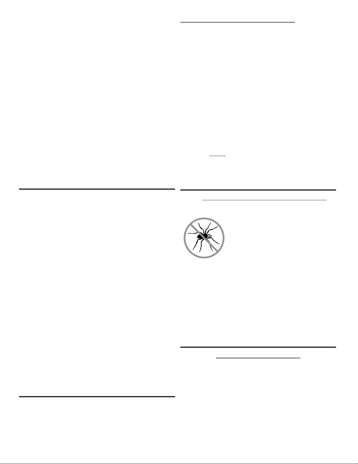
n CAUTION: BEWARE OF FLASHBACK
CAUTION: Spiders and small insects occasionally spin
webs or make nests in the
grill burner tubes during
transit and warehousing.
These webs can lead to a
gas flow obstruction which
could result in a fire in and
around the burner tubes.
This type of fire is known as a ”FLASHBACK” and can
cause serious damage to your grill and create an unsafe
operating condition for the user.
Although an obstructed burner tube is not the only cause of
”FLASHBACK”, it is the most common cause.
To reduce the chance of ”FLASHBACK”, you must clean the
burner tubes before assembling your grill, and at least once
a month in late summer or early fall when spiders are most
active. Also perform this burner tube cleaning procedure if
your grill has not been used for an extended period of time.
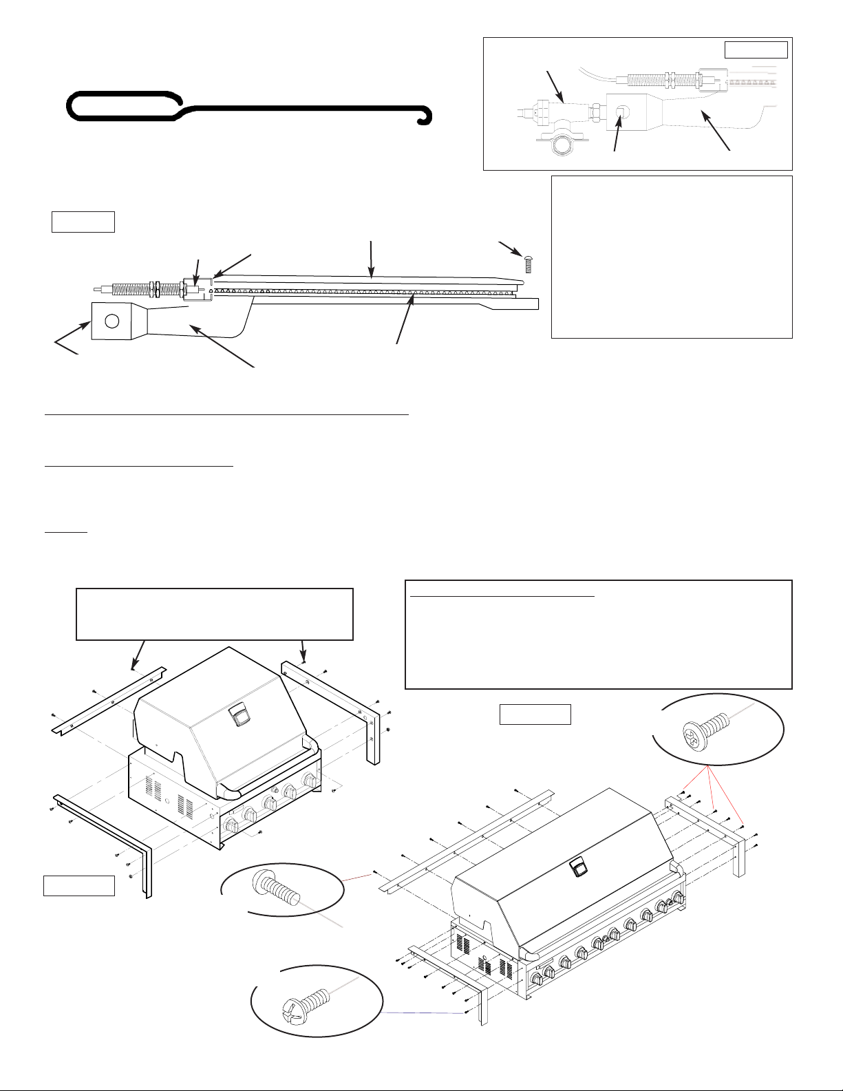
BEFORE USING YOUR GRILL
To reduce the chance of ”FLASHBACK” clean the burner tubes and burners before fully assembling your grill.
Unscrew the bolt at the rear of the burner using a screwdriver. Carefully lift each burner up and away from the gas
valve orifice, then refer to Fig1 and perform one of these
three cleaning methods:
1. Bend a stiff wire, (a lightweight coat hanger works well)
into a small hook as shown below. Run the hook through
the burner tube and inside the burner several times to
remove any debris.
- 3 -
2. Use a bottle brush with a flexible handle. Run the brush through
the burner tube and inside the burner several times, removing any
debris.
3. Preferably, an air hose should be used to force air through each
burner tube. The forced air should pass debris or obstructions
through the burner and out the ports.
Figure 1
GAS VALVE
ASSEMBLY
BURNER TUBE
ORIFICE
Figure 2
SPARK
ELECTRODE
ASSEMBLY
BURNER TUBE
PHILLIPS HEAD
SCREW
BURNER PORTS
BURNER
GAS
COLLECTOR
BOX
n
WARNING
The location of the burner tube with
respect to the orifice is vital for safe
operation. Check to ensure the orifice
is inside of the burner tube before
using your gas grill (Figure 1).
If the burner tube does not fit over the
valve orifice, lighting the burner may
cause explosion and/or fire.
- 4 -
Outdoor BBQ Built-in Installation Specifications
Prior to installing unit, side and rear trims must be installed to fully support the unit.
Built-in T
rim Kit Installation:
Carefully remove the stainless steel trim pieces from the carton and attach Left, Right & Rear stainless trims to left, right &
rear sides of barbecue using 10 bolts & 2 nuts. Check to make sure they are aligned flush with the side barbecue face
and top before fully tightening the bolts.
NOTE:
When choosing a location for your Gas grill, keep in mind that it should not be located under any overhead com-
bustible construction. The side and bottom of the grill should not be any closer than 18 inches to combustible construction,
and the back of the grill should not be any closer than 24 inches to combustible construction.
TO CLEAN BURNER TUBE
INSERT HOOK HERE
Figure 3a
Rear Trim:
52" BBQ uses 4 bolts
38" BBQ uses 3 bolts and Wok uses 2 bolts
YN662AGLP , YN662AGNG
Rear Trim:
(A) - (6X) 3/16” x 3/8” Phillips Head Screws
Left & Right Trim:
(B) -(6X) 3/16” x 3/8” Pan Head with Cross Recess Screw
(C) -(10X) 1/4” x 1/2” Phillips Head Screw
Figure 3b
6X (A)
10X (C)
6X (B)
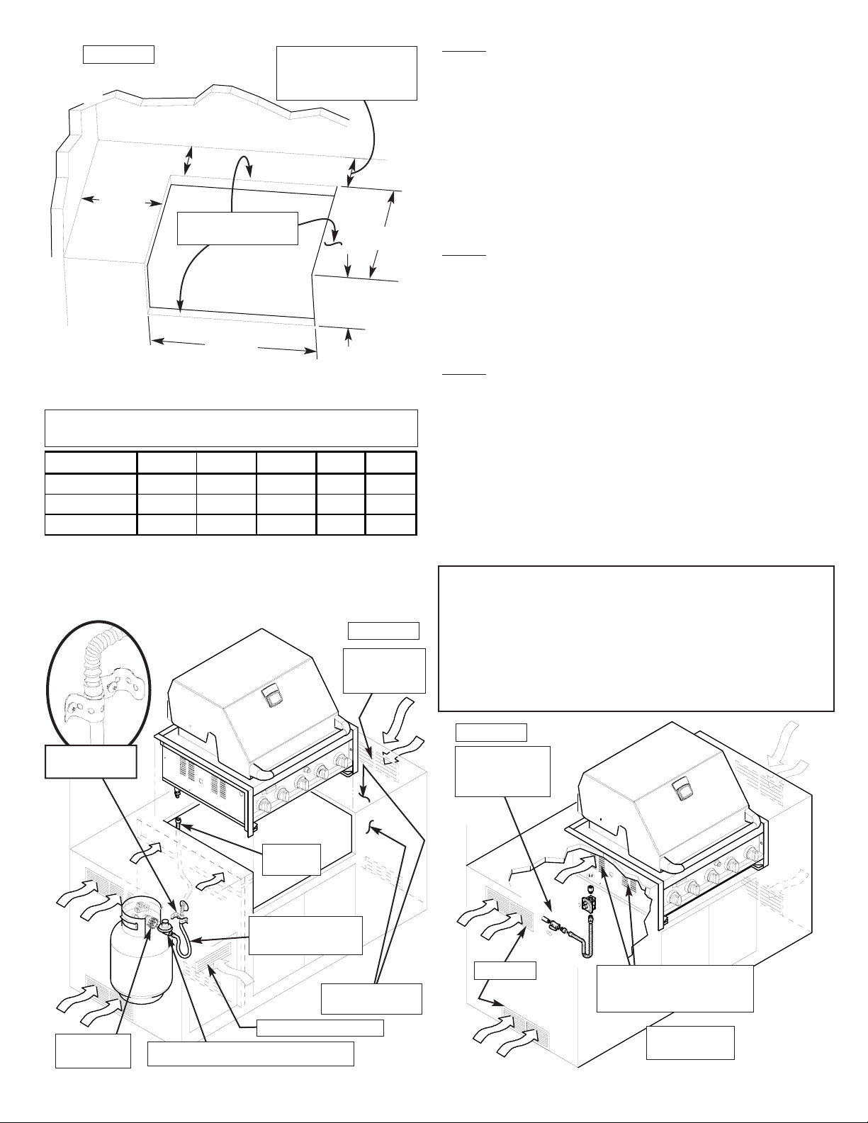
NOTE: When using Propane, EXTREME CAUTION should be
used to provide ample ventilation of vapor from the enclosure.
LP Gas vapor is heavier than air and SERIOUS INJURY from
a DANGEROUS EXPLOSION could occur if LP Gas is allowed
to accumulate in an enclosure and then ignited. Both the
Barbecue enclosure and LP cylinder enclosure require venting
that must be provided at the floor level of the enclosure to allow
any leaking LP Gas vapor to escape. Upper & lower groundlevel vents (20 sq. in. minimum each) MUST BE PROVIDED
on both sides of built-in construction. Please ask a Barbeques
Galore associate for full details.
NOTE:
When installing a barbecue equipped for liquid propane
in an island, the propane tank must be in a separate enclosure
that is completely isolated from the barbecue. It must be crossventilated in accordance with the current standard. The
propane tank MUST NEVER be installed directly under the barbecue.
NOTE:
Upper & lower ground-level vents (20 sq. in. minimum
each) MUST BE PROVIDED for combustion air on both sides
of built-in construction. Please ask a Barbeques Galore associate for full details.
Barbecues must be installed in accordance with CSA
specifications and all local building codes.
Air Vents
Louvers on BBQ must
remain unobstructed to
allow for combustion air.
Figure 6
Natural Gas
Installation
Access must
be provided to
Shut-off Valve
- 5 -
Depth
Width
Height
Side*
Rear*
6” minimum clear-
ance from cutout
(for hood)
Model Height Width Depth Side* Rear*
52" YN662 10" 52-3/4" 24-1/2" 18" 24"
38" YN663 10" 38-3/4" 24-1/2" 18" 24"
Side Burner 10" 17-1/2" 24-1/2" 18" 24"
non-combustible
construction
Built-in Model Cutout Dimensions &
Clearance to Combustibles
* Rear & Side Clearances indicated are to combustible
construction
Figure 4
nWARNING
Vapors from products containing Chlorine and other caustic
chemicals can cause Stainless Steel flexible connectors to
corrode. THESE PRODUCTS SHOULD NOT BE STORED IN
AN ISLAND OR NEAR THE connector. Cleaning solutions,
Household Chemicals and Solder fluxes can also cause pinholes if they come in contact with these connectors and
MUST be washed off immediately with water.
Stainless
Flexline
Non-combustible
Construction
Vented on
BOTH SIDES
of Island
Vented Access Door
CSA Approved Propane Regulator
CSA Approved
Rubber Gas Hose
QCC-1/OPD
Tank
Figure 5
Clamp down
flexline
- 6 -
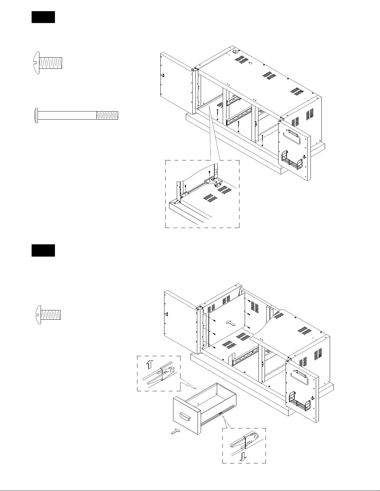
Cart & Barbecue Assembly (requires an assistant)
1. Unpack Cart.
2. Unpack Barbecue.
3. Position barbecue on top of Cart.
4. Remove Left & Right Side Panels on both sides of cart
as shown in Figure 9.
5. With the help of your assistant, position barbecue on
top of Cart and align mounting holes as shown in Figure
10.
6. Secure with two Mushroom Head bolts and nuts at both
front sides. Do not tighten until all fasteners are in
place.
7. Secure with Washer Head bolts (no nuts required) as follows:
YN662 (52” BBQ’s) 6 bolts at rear & side
YN663 (38” BBQ) 5 bolts at rear & side
You may need your assistant to adjust the position of the
barbecue so that the holes are all aligned.
8. Once barbecue & cart are aligned, tighten all bolts.
9. Replace Left & Right Side Panels.
Figure 9
Figure 7
NATURAL GAS MODELS ONLY
Side Panel
Bolts
CSA Approved
Rubber Gas Hose
Cart model LP Gas
Connection
3/8 FF x 3/8 MF
on Propane models
Figure 10
Nutserts
Washer
Head
Bolts
Nuts at
front only
(2)
Bolts
Figure 8
IN
OUT
CSA Approved
Natural Gas
Regulator
Yellow Teflon Pipe Thread Sealant
is recommended for use on all
pipe thread connections EXCEPT
flared threads.
Stainless
Flexline
Natural
Gas
Supply
Close Nipple
Shut-off Valve
1/2-1/2” NPT
IMPORTANT: Regulator must be on the Barbecue or your
warranty is void.
Extension Fitting for manifold
Extension Fitting for outlet (NG only)
Grand Turbo YN662CT, YN663CT Models
P81201013A
Cart & Cart Trim Plate Assembly Instructions
1
3/16"x1/2” Phillips Head Screw
Qty. 12
(from left & right cart side panel
trim plate)
Cart & Cart Trim Plate Assembly (requires an assistant)
1. Open the left door from cabinet cart. Unscrew the left cart side panel trim plate from the left cart side
panel.
2. Repeat for right cart side panel trim plate.
3. Pull out the upper drawer, Push up black tenon on the left slide and push down black tenon on the right
slide to remove the upper drawer.
4. Repeat for lower drawer.
2
1. Place the cart trim plate under the cart.
2. Be sure the rear of cart trim plate are inserted into the cart trim plate bracket.
- 7 -
3
Align the holes on the cart bottom shelf
and the caster seats
with the threaded holes on the cart trim plate.
Tighten securely using 4 screws and 3 bolt provided.
1/4”x1/2”Phillips Head Screw
Qty. 4
1/4"x2-1/2" Pan Head with Cross
Recess Bolt
Qty. 3 (for YN662CT Model)
Qty. 2 (for YN663CT Model)
4
2. Repeat for right cart side panel trim plate.
3. Install the upper drawer, Push up black tenon on the left slide and push down black tenon on the right
slide to install the upper drawer to cart.
4. Repeat for lower drawer.
3/16"x1/2” Phillips Head Screw
Qty. 12
(from left & right cart side panel
trim plate)
1. Install the left cart side panel trim plate to the left cart side panel.
- 8 -
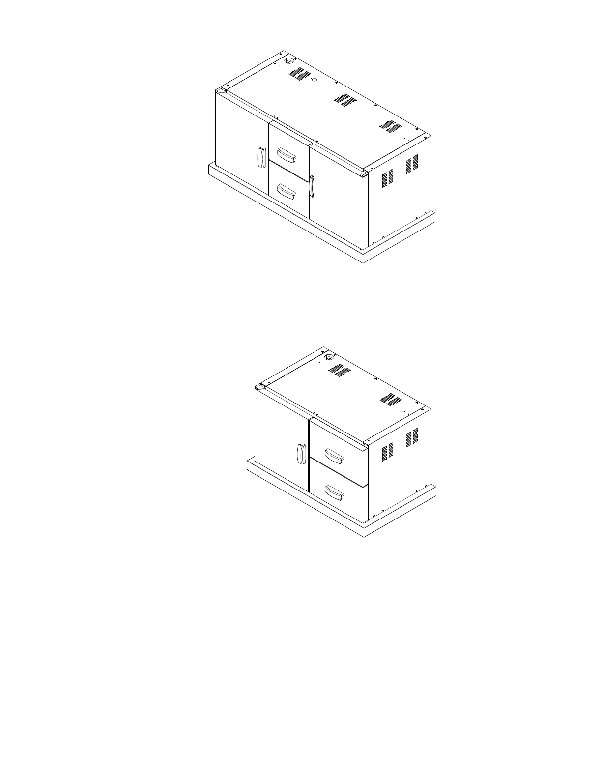
YN662CT Model
YN663CT Model
- 9 -
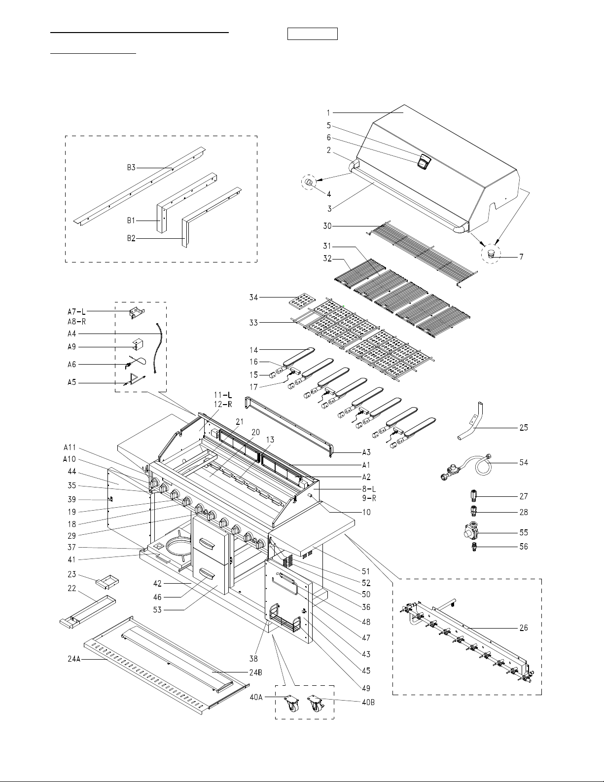
YN662AGLP , YN662AGNG
Parts Diagram
Figure 11
- 10 -
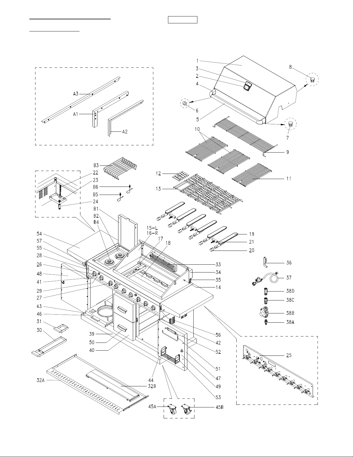
YN662LP , YN662NG
Parts Diagram
Figure 12
- 11 -
 Loading...