

Grandhall XI08ALP, XI08ANG Operator's Manual

NOTE TO ASSEMBLER / INSTALLER:
Leave this manual with the consumer.
NOTE TO CONSUMER:
Keep this manual for future reference.
RECORD YOUR SERIAL # __________________
(see silver CSA label on main body of grill)
Ÿ
Ÿ
IMPORTANT:
Ÿ
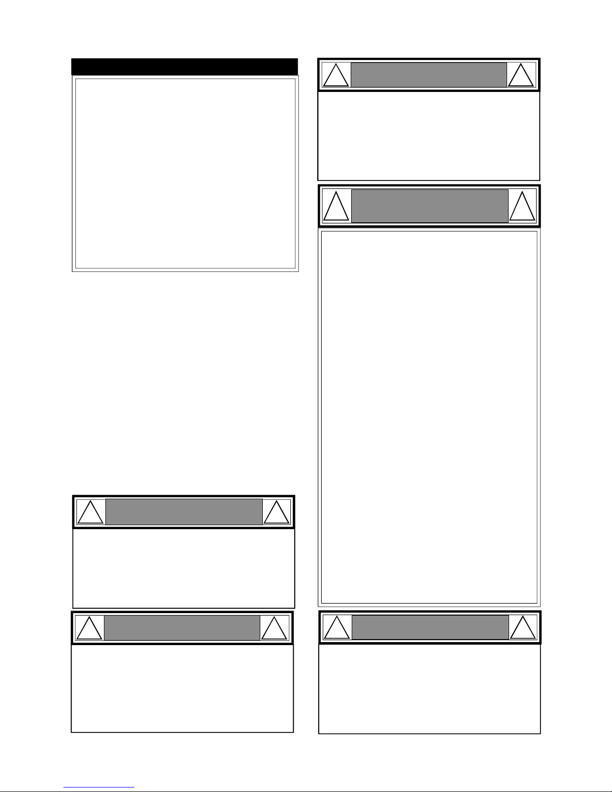
Failure to comply with these instructions could
result in a fire or explosion that could cause
serious bodily injury, death or property damage.
Whether this grill was assembled by you or
someone else, you must read this entire manual
before using your grill to ensure the grill is
properly assembled, installed and maintained.
Use your grill at least 3 feet away from any
wall or surface. Use your grill at least 3 feet
away from combustible objects that can melt or
catch fire such as vinyl or wood siding, fences
and overhangs or sources of ignition including
pilot lights on water heaters and live electrical
appliances.
THIS GAS APPLIANCE IS DESIGNED FOR
OUTDOOR USE ONLY.
Never use your gas grill in a garage, porch,
shed, breezeway or any other enclosed area.
Never obstruct the flow of ventilation air
around your gas grill housing.
Never disconnect the gas regulator or any gas
fitting while your grill is lit. A lit grill can ignite
leaking gas and cause a fire or explosion which
could result in property damage, personal injury or death.
Ÿ
Ÿ
Ÿ
Ÿ
Ÿ
Ÿ
WARNING
! !
Operator's Manual
Liquid Propane Gas (LPG) Grill
Model XI08ALP
Natural Gas (NG) Grill
Model XI08ANG
FREE HELP
FROM THE GRILL EXPERTS
Ÿ
Manual # P80134004A - Date:2009/02/27
At Grand Hall we're the experts on this
product and trained to help you with:
visit www.grandhall.com or call:
1-877-934-7455
Monday - Friday 8:00am-4:30pm CST
Assembly Questions
Grill Operation
Replacement of Damaged or Missing parts
Ÿ
Ÿ
Ÿ
XI08ALP
XI08ANG
2
Table of Contents
Primary Safety Warnings...........................1-3
Pre-Assembly Instructions..............................3
Part Diagrams and Lists..........................4-7
Assembly Instructions...............................8-12
Use & Care Instructions:
• Gas Safety and Leak Tests...........13-16
• Natural Gas Connection.........................16
• Use & Care Instructions - LCD......17-18
• Lighting Instructions.................................19
• Troubleshooting..........................................20
• Rotisserie Instruction...........................21-23
Cleaning and Maintenance..........................24
Cooking Guide........................................A1-A5
Frequently Asked Questions................A6-A7
Warranty Terms............................Back Cover
WARNING
! !
This appliance, when installed, must be electrically grounded in accordance with local codes
or, in the absence of local codes, with the
National Electrical Code, ANSI/NFPA 70, or the
Canadian Electrical Code, CSA C22.1.
Keep any electrical supply cord and the fuel
supply hose away from any heated surfaces.
•
•
Do not store or use gasoline or other
flammable liquids or vapors in the
vicinity of this or any other appliances.
An LP cylinder not connected for use
shall not be stored in the vicinity of
this or any other appliance.
1.
2.
WARNING
! !
Always keep the Grease/Water Tray 1/2 filled
with water during operation. Failure to follow this could result in a grease fire that could
cause serious bodily injury or property damage.
1.
2.
WARNING
! !
Handle this Grease/Water tray with a flame
retardant BBQ mitt.
WARNING
! !
•
LPG models must be used with Liquid Propane
Gas and the regulator assembly supplied. Natural Gas models must be used with Natural Gas
only. Any attempt to convert the grill from one fuel
type to another is extremely hazardous and will
void the warranty.
Keep gas regulator hose away from hot grill
surfaces and dripping grease. Avoid unnecessary
twisting of hose. Visually inspect hose prior to
each use for cuts, cracks, excessive wear or other
damage. If the hose appears damaged do not use
the gas grill. Call 1-877-934-7455 for a certified
replacement hose.
California Proposition 65
Combustion byproducts produced when using this
product contain chemicals known to the State of
California to cause cancer, birth defects, or other
reproductive harm.
Brass components on the grill, such as hose fittings, propane cylinder valves (sold separately) and
burner valve stems, contain lead which is known to
the State of California to cause cancer, birth defects,
or other reproductive harm.
Never use charcoal or lighter fluid in this gas grill.
Failure to comply with these instructions could result in a grease fire or explosion that could cause
serious bodily injury, death or property damage.
The Grease Tray must be visually inspected before
each grill use. Remove any grease and wash Grease
Tray with a mild soap and warm water solution.
Failure to comply with these instructions could
result in a grease fire or explosion that could
cause serious bodily injury, death or property
damage.
•
•
•
•
DANGER
!
!
1.
2.
3.
4.
If you smell gas:
Shut off gas to the appliance.
Extinguish any open flame.
Open lid.
If odor continues, keep away from the
appliance and immediately call your
gas supplier or your fire department.
Patents held by Grand Hall include the following:
Grand Hall and design®, DS Grill and design®,
Crossray™ Lateral Infrared Burner Technology, Command Flame®, Smooth Start® Electronic Ignition System,
Ceramic Savor Plates®, Sear-zzler®, Stainless Clad
Therma-Core® Cooking Grids, Grand Café and design®,
Grand Mark and design®, Grand Chef and design®,
Grand Royale and design®, Globe Café and design®,
Urban Café and design®, Smokeless Grill and design®.
Registered and unregistered Trademarks held by
Grand Hall include the following:
©2008 Grand Hall. All Rights Reserved.
The Crossray Burner System by Grand Hall is covered
by Australian Patent No. 2006100635, Chinese Patent
No. 960361, European Patent Pending, French Patent
0607231, German Patent No. 20 2006 012 212.5, U.K
Patent GB2440714, and U.S. Patent 7,475,632.
3
Pre-Assembly Instructions For Your Safety
To begin your “restaurant quality” grilling, become familiar
with all of the cooking elements of your Grand Hall Grill
lighting and operating instructions.
IMPORTANT NOTE: Your infrared Grand Hall Grill is
equipped with an innovative Grease/Water Tray that is designed to trap excess grease drippings but also to moisturize your food. It is important to keep this tray half-filled with
water while grilling in order to get the best possible results.
WARNING: Grease and water can get very hot. Always
handle the Grease/Water Tray with a flame retardant BBQ
mitt. Before removing the Tray, always be sure that the grill
has properly cooled. Be aware that the tray does contain
water and grease and be extremely careful when removing
the tray to prevent spillage. Failure to follow these instructions could cause serious bodily injury or property damage.
Congratulations on your selection of one of the finest outdoor kitchen appliances available. Your Grill is equipped
with the unique Crossray Infrared Cooking System® by Grand
Hall, which offers restaurant style grilling performance.
Infrared grilling technology cooks the food directly (and not
the air around it) which offers many advantages over con-
MORE FLAVORFUL FOOD as the intense heat sears the
food and locks in the juices while also cooking it faster
which usually means more succulence.
FEWER FLAREUPS as the higher infrared heat vaporizes more drippings which also adds natural flavoring to
your food.
MORE EFFICIENCY AND CONVENIENCE as the higher
heat means shorter cooking times, more fuel efficiency
and easier year round grilling.
Grill Installation Codes
The installation must conform with local codes or, in the
absence of local codes, with either the National Fuel Gas
Code, ANSI Z223.1/NFPA 54, Natural Gas and Propance
Installation Code, CSA B149.1, or Propane Storage and
Handling Code, B149.2.
•
•
•
PRE-ASSEMBLY
Read and perform the following pre-assembly instructions:
1-877-934-7455 M-F 8AM-4:30PM CST for assistance.
Tools Required for Assembly:
protective work gloves
protective eyewear
#2, #3 Phillips head screwdriver
You will need assistance from two people to handle
the grill head and other large, heavy parts.
Open Lid of shipping carton and remove top sheet of
cardboard and packing materials. Lay cardboard
sheet on floor and use as a work surface to protect
floor and grill parts from scratches.
You may slice the carton front corners with a utility knife
to lay open the carton front panel. This allows you to
raise the Lid and remove the components packed inside, making it easier to lift.
Use the Hardware and Part Diagrams to ensure all items
are included and free of damage.
Do not assemble or operate the grill if it appears damaged. If there are damaged or missing parts when you
unpack the shipping box or you have questions during
the assembly process call
Europe Patent Pending
Australia Patent No.: 2006100635
Germany Patent No.: 202006012212.5
France Patent No.: 0607231
UK Patent No.: GB2440714
China Patent No.: 960361
US Patented.: 7,475,632
ventional grilling systems:
Hardware Pack Parts List for Models XI08ALP & XI08ANG
PART #
PART DESCRIPTION
QTY
PURPOSE OF PART
P06030003A
Hardware Pack
1
For use in assembly of Model XI08ALP
P06030007A
Hardware Pack
1
For use in assembly of Model XI08ANG
S125G04092Phillips Head Screw, PT 1/4"x1-5/16" 16
Install Island Side Panel Bracket Assembly
S182G03062
Pan Head Screw 3/16"x3/8"
4
Install Rotisserie Motor
S164G04121Socket Head Cap Screw 1/4"x3/4" 4
P05515006BWrench/M3 1
S355G04001Wing Nut 1/4" 4
S411G05101Plain Washer 5/16" 4
P05515129CWrench 1
S192G03062Pan Head Screw 3/16"x3/8" 4
S165G04092Hex Head Screw, PT 1/4"x2-1/16" 8
S313G04062Flange Nut 1/4" 8
S182G04062Pan Head Screw 1/4"x3/8" 4
Install Partition Panel Bracket to Island Decorative Panel
(For XI08ALP Model)
S182G03062Pan Head Screw 3/16"x3/8" 8
Install Island Decorative Panel
S162G04062Hex Head Screw 1/4"x3/8" 4
Install Partition Panel (For XI08ALP Model)
P05515128YWrench/M5 1 For use in removing/installing the replacement part for Lid
Install Island Side Panel Set
Install Island Side Panel Bracket to Island Side Panel Set
4
* One Battery/AA included in the Hardware Pack.
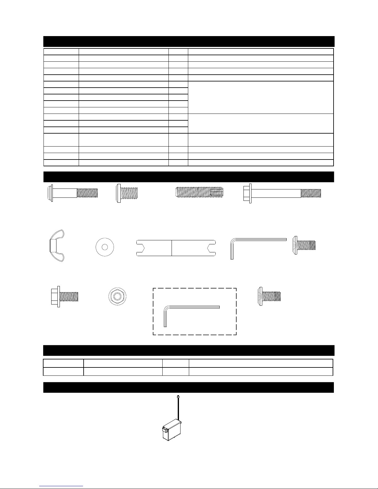
Back Up Battery Parts List for Models XI08ALP & XI08ANG
Back Up Battery Diagram for Models XI08ALP & XI08ANG
PART # PART DESCRIPTION QTY PURPOSE OF PART
P05301005Q Spare Battery Box 1 Temporary Replacement for the Battery Pack/Rechargeable
Spare Battery Box
Qty. 1
Part # P05301005Q
Wrench/M5
Qty. 1
Part # P05515128Y
For use in Removing/Installing
replacement part for Lid Hinge
Hardware Pack Diagram for Models XI08ALP & XI08ANG
Hex Head Screws
1/4"x3/8"
Qty. 4 (LPG Model)
Part # S162G04062
Flange Nut 1/4"
Qty. 8
Part # S313G04062
Phillips Head Screw,
PT 1/4"x1-5/16"
Qty. 16
Part # S125G04092
Wrench/M3
Qty. 1
Part # P05515006B
Wing Nut 1/4"
Qty. 4
Part # S355G04001
Plain Washer 5/16"
Qty. 4
Part # S411G05101
Wrench
Qty. 1
Part # P05515129C
Pan Head Screw
3/16"x3/8"
Qty. 12
Part # S182G03062
Pan Head Screw
1/4"x3/8"
Qty. 4 (LPG Model)
Part # S182G04062
Socket Head Cap
Screw 1/4"x3/4"
Qty. 4
Part # S164G04121
Hex Head Screw,
PT 1/4"x2-1/16"
Qty. 8
Part # S165G04092
Pan Head Screw
3/16"x3/8"
Qty. 4
Part # S192G03062
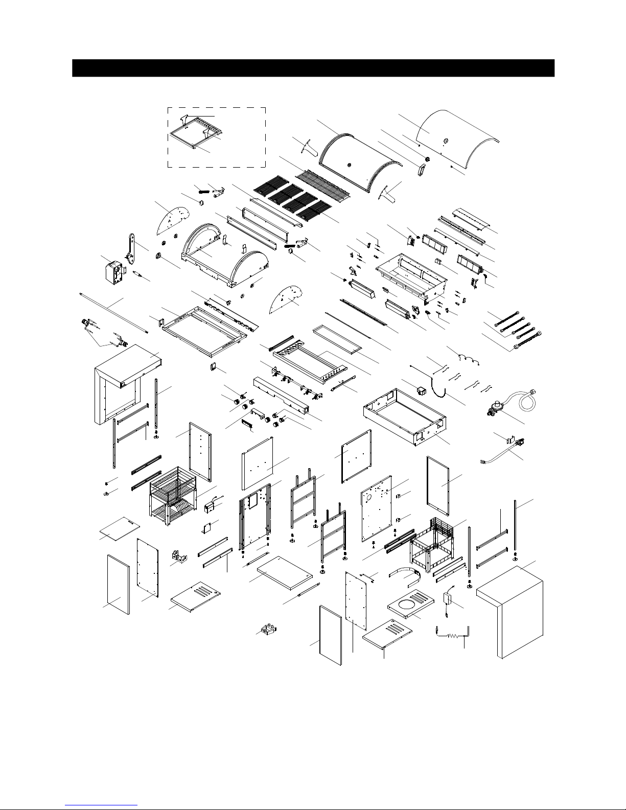
Parts Diagram for Models XI08ALP & XI08ANG
5
24a
60
15
14
13
6
6
26
58
59
82
80
81
79
78
77
77
76
75
74
73
72
71
70
67
69
68
67
66
65
64
63
61
61
41
40
24b
23
10
57
51
52
53
55
48
45
44
43
25
39
36
34
35
37
32
31
30
29
28
27
7
21
20
9
8
3
5
4
1
2
5
11
12
16
18
17
28
42
33
38
31
29
42
19
22
56
54
78
63
64
30
83
84a
84b
85
86
38a
49
50
8a(optional)
8b(optional)
8b(optional)
14a
14a
1a
1a
47
45a
46
45a
45
7a
7b
41a
41a
87
88
89
90
90
91
92
93
42
42
62
Parts List for Models XI08ALP & XI08ANG
6
KEY
DESCRIPTION
PART#
QTY1Lid Assembly Outer
P0014513A5
11aProtective Pad
P05518018I
22Temperature Gauge
P00601371A
13Lid Handle
P00215034F
14Lid Assembly Inner
P0014514E5
15Lid Hinge
P05547004D
26Lid Bracket
P033031165
27Motor Transmission
P05378002B
17aMotor/DC
P07102002A
17bGear Shaft
P05508201C
18Cooking Rack/Secondary
P015160275
19Cooking Grid
P01615035F
4
10
Gas Fitting
P03907008A
111Bowl Panel, Rear/Upper
P007560265
112Bowl Panel Fixed Shield, Rear/Upper
P0075603E5
113Lid Spring Bracket Set, Left
P055510037
1
14
Lid Spring Bracket Set, Right
P055510047
1
14a
Protective Pad for Spring Bracket
P05518045I
2
15
Spring
P05504113N
2
16
Bowl Frame A Panel, Rear
P007259865
1
17
Bowl Frame A
P0071363S5
1
18
Bowl Frame A Bracket
P013180035
2
19
Regulator with Hose Assembly (LPG)
P03603050A
120Bowl Frame Trim panel, Left
P0072091B5
121Bowl Frame Trim panel, Right
P0072192B5
122Regulator with Hose Assembly (NG)
P03628003A
123Cooking Rack Bracket/Secondary
P01529001A
4
24a
Spit Bracket - Left
P05552001A
1
24b
Spit Bracket - Right
P05552002A
1
25
Control Panel Heat Shield
P0300917EB
126Bowl Frame B
P013180055
127Grease Tray Heat Shield
P069040485
128Grease Shield, Lower
P069021245
229Grease Shield, Upper
P069021255
230Infrared Burner Assembly
P020050235
431Cross Lighting Channel
P02212377A
232Bowl Assembly
P0073957E5
133Thermocouple for Gas Valve
P05305047A
234Thermocouple for Gas Valve
P05305040D
235Thermocouple for LED Light - Long
P05305048A
236Thermocouple for LED Light - Short
P05305049A
237Thermocouple Bracket
P03327058C
238Thermocouple Bracket
P03327059C
2
38a
Thermocouple/Ignition Electrode Cover
P03343015C
439Ignition Electrode
P02614055A
440Grease Tray
P02717575B
141Grease Tray Bracket Assembly
P03327073D
1
41a
Grease Tray Bracket Slide Set
P05516140M
1
Orifice (LPG)
P06539028A
4
Orifice (NG)
P06539029A
4
Gas Valve/Manifold Assembly (LPG) Y0060657 1
Gas Valve/Manifold Assembly (NG) Y0060658 1
Control Panel (LPG) P02914208A 1
Control Panel (NG)
P02914208F
145Control Knob Seat with LED Light and Wire - Long
P03401394V
2
45a
Control Knob Seat with LED Light and Wire - Short
P03401414V
246Control Knob
P03401424V
447LCD Heat Insulating Spacer
P05357005D
148LCD Assembly
P05357006B
1
49 Rot. Holding Fork P05508198M 2
50 Rot. Spit P05508199A 1
51 Connection Hose - Long P03720001F 2
43
44
42
Parts List for Models XI08ALP & XI08ANG
7
KEY DESCRIPTION PART# QTY
8a Griddle (optional) P057050035 1
8b Griddle Handle (optional) P055151255 2
Cover (optional) P07007055A 1
Optional Parts to Purchase for Models XI08ALP & XI08ANG
Important: Use only Grand Hall replacement parts. The use of any part that is not a Grand Hall replacement part can be dangerous
and will also void your product warranty. Keep this Operator's Manual for convenient referral and for part replacement.
To obtain the correct replacement parts for your gas grill, please refer to the part numbers in this parts list. The following
information is required to ensure you receive the correct parts:
1. Model and Serial Number (see CSA label on grill)
2. Part Number
3. Part Description
4. Quantity of parts needed
For the repair or replacement parts you need:
Call 1-877-934-7455 M-F 8AM-4:30 PM CST
KEY DESCRIPTION PART# QTY
52
Connection Hose - Short
P03702035F
253Connection Hose
P03715016F
154NG Regulator Bracket (NG)
P033110415
155Electric Wire, 4-Contact
P02627011A
156Electric Wire Set
P02615150A
157Lighting Stick
P05507140M
158Electric Ignitor, 4-Port
P02502364C
159Battery Pack/Rechargeable
P05301008B
160Battery Bracket
P03348001D
161Side Panel, Island
P011060495
262Cord Holder
P055530013
163Bracket/Island
P03334006D
464Connection Bracket/Island
P03331017D
465Panel, Left/Rear/Island
P07702107B
166Panel, Right/Rear/Island
P07702108B
167Door
P04304010B
268Door Trim Panel, Left
P04316002B
169Door Trim Panel, Right
P04316003B
170Basket, Left
P05203009G
171Basket, Right
P05203010G
172Panel, Left/Island
P07617047B
173Panel, Right/Island
P07618048B
174Decorative Panel, Left/Island
P07605034B
175Decorative Panel, Right/Island
P07606036B
176Frame Assembly/Island
P01306027D
177Side Panel Bracket Assembly/Island
P03334007D
278Slide Set
P05516045L
479Bottom Panel, Left/Island
P01001039D
180Bottom Panel, Right/Island
P01001040D
181Tank Tray
P04021010C
182Towel Rack
P05212014A
183Partition Panel (LPG)
P07515021B
1
84a
Partition Panel Bracket, Left (LPG)
P03303126D
1
84b
Partition Panel Bracket, Right (LPG)
P03303127D
185Charger
P05384001B
186Temperature Probe
P05385001B
187End Cap, Leg
P06802008G
1288Level Adjuster A
P05322005B
889Level Adjuster B
P05322006A
490Hose Holder (NG)
P03338003D
291Tank Fastening Strap (LPG)
P05314002V
192Cutting Board
P02401004A
193Grate Handle Hook
P05514135G
1
Hardware Pack (LPG)
P06030003A
1
Hardware Pack (NG)
P06030007A
1
Operator's Manual
P80134004A
1
Assembly Instructions
CAUTION : To assemble this grill, you should obtain assistance from 2 people when handling the larger, heavier pieces.
Phillips Head Screw,
PT 1/4"x1-5/16"
Qty. 16
Part # S125G04092
2
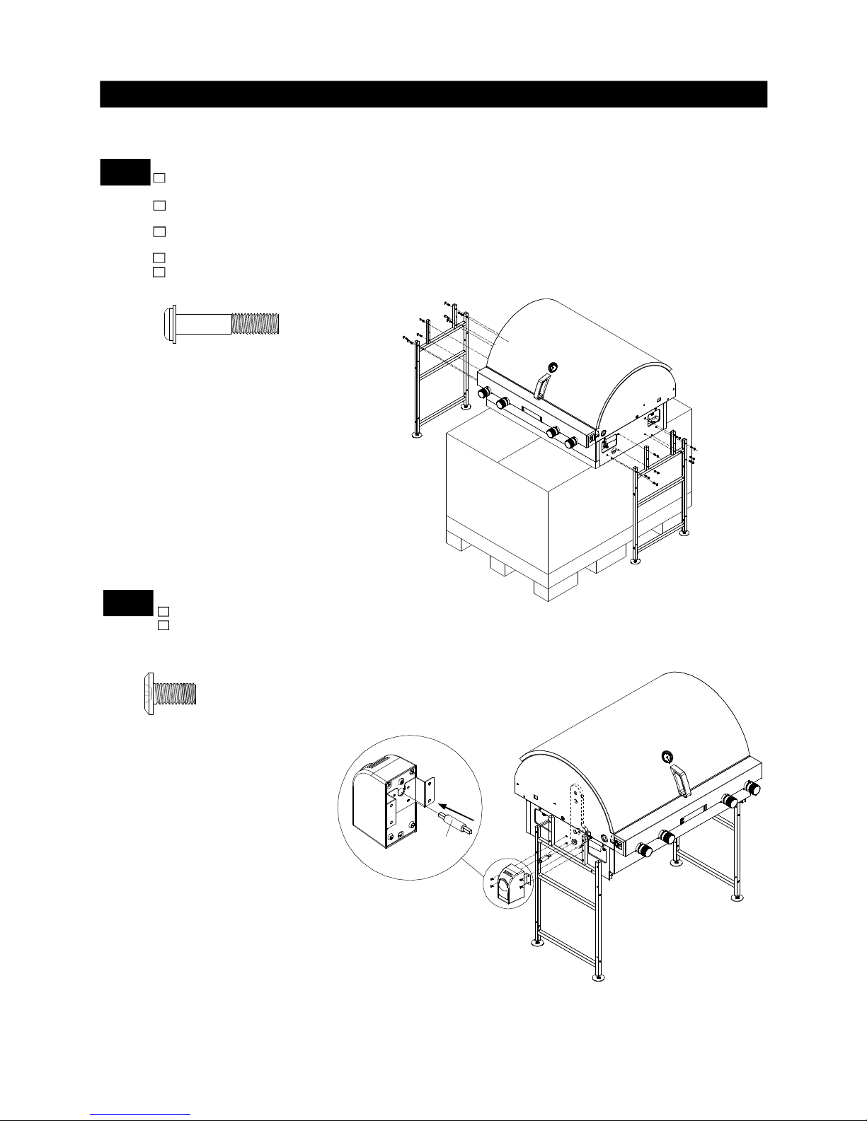
Install Rotisserie Motor
Insert the Gear Shaft into the Rotisserie Motor as shown in diagram below.
Insert the other end of the Gear Shaft with Motor into the hole on the Motor Transmission. Next,
align the 4 holes on the Motor Bracket with the 4 holes on the Left Grill Bowl, then insert 4 Pan
Head Screws 3/16"x3/8" and tighten as shown.
8
Gear Shaft
1
Install Island Side Panel Bracket Assembly
Lay a piece of cardboard on the ground (refer to Pre-Assembly Instructions). With the help of your assistant,
remove the Grill Head from the box and put it on the cardboard. Reserve the box for next step.
Remove all cooking components from the Grill Head. Raise the Grill Head and put it on top of the box
as shown.
Align the 8 holes on the Left Island Side Panel Bracket Assembly with the 8 holes on the Left Bowl
Panel. Insert 8 Phillips Head Screws, PT 1/4"x1-5/16" and tighten securely.
Repeat previous steps for the Right Island Side Bracket Assembly.
Once the Bracket Assemblies have been securely installed, place the Grill Head with Bracket Assemblies
onto the ground. Carefully remove the box from underneath the Grill Head.
Pan Head Screw 3/16"x3/8"
Qty. 4
Part # S182G03062
3
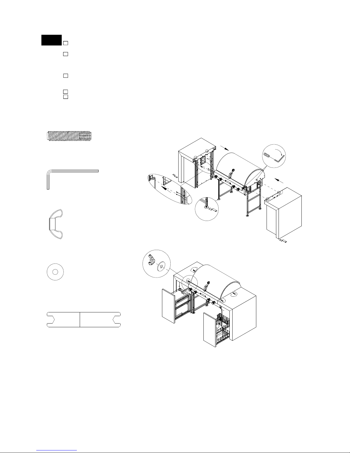
Install Island Side Panel Sets
Insert 2 Socket Head Cap Screws 1/4"x3/4" into the Bowl Frame Trim Panel/Left. Tighten and secure
using the Wrench/M3 as shown.
With your assistants, lift the Side Panel, Left/Island and slide it towards the Left Island Side Bracket
Assembly. Insert the 2 Electric Wires from the left side of the Control Panel into the holes on the Bowl
Frame Trim Panel/Left and the Side Panel, Left/Island as shown. Align them by making sure the 2 Socket
Head Caps in the Bowl Frame Panel go into the holes in the Island Side Panel Bracket Assembly.
Open the Left Island Door. Find the ends of the 2 Socket Head Cap Screws (they should be where the
Bowl Frame Trim Panel/Left and Side Panel, Left/Island meet). Install 1 Plain Washer 5/16" onto each
Socket Head Cap Screw. Secure by installing 1 Wing Nut 1/4" on top of each washer.
Repeat previous steps for the Side Panel Right/Island.
If the Island Side Panels and the Grill are not level with each other, use the wrench to adjust the level
adjusters on the bottom of the Bracket Assemblies.
Turn the adjusters clockwise to raise the height of the Grill.
Turn the adjusters counterclockwise to lower the height of the Grill.
FOR YOUR SAFETY DO NOT TILT your Grill at any time.
Wing Nut 1/4"
Qty. 4
Part # S355G04001
Socket Head Cap
Screw 1/4"x3/4"
Qty. 4
Part # S164G04121
Wrench/M3
Qty. 1
Part # P05515006B
9
Wrench
Qty. 1
Part # P05515129C
Plain Washer 5/16"
Qty. 4
Part # S411G05101
•
•
•
10
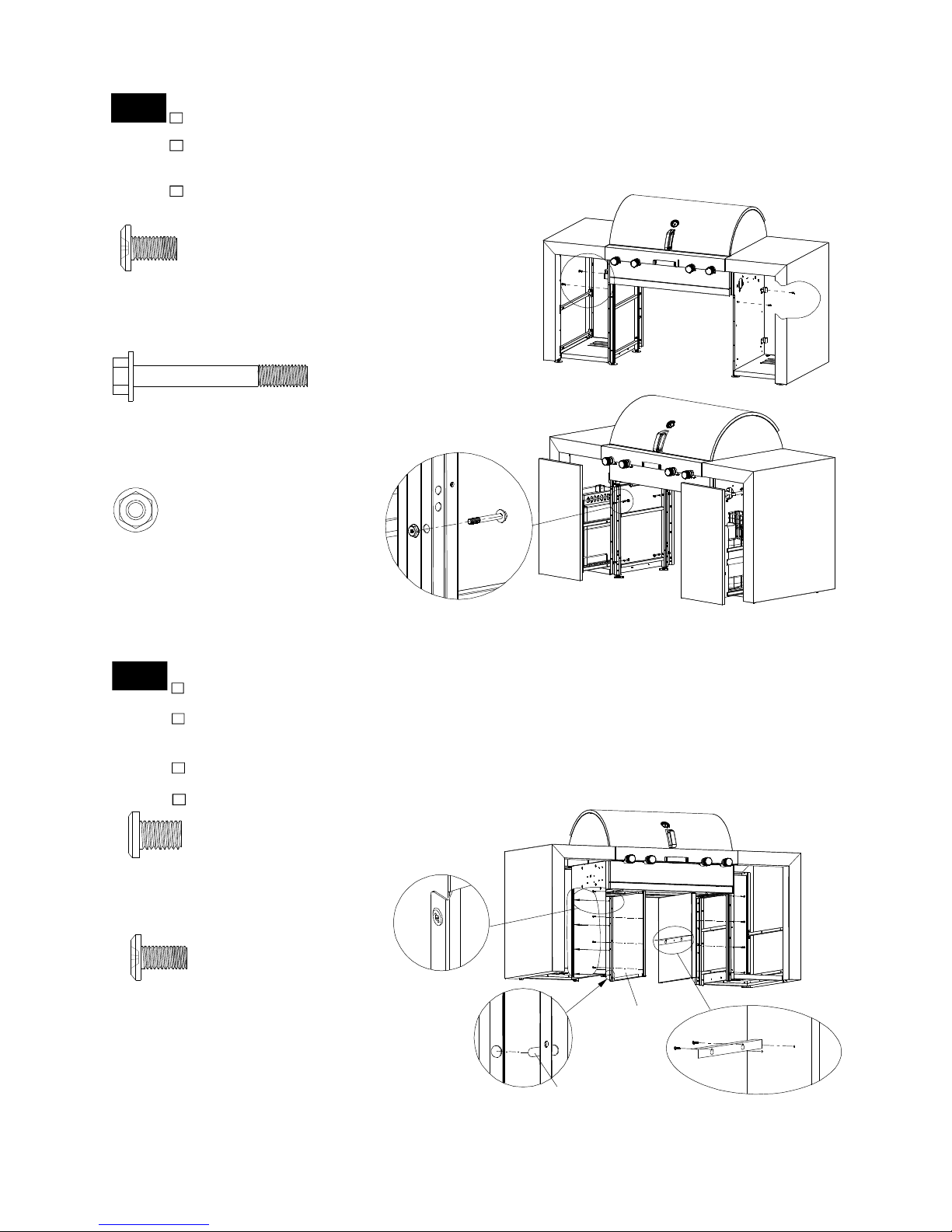
4
Install the Island Side Panel Bracket Assemblies onto the Island Side Panel Sets
Align the 2 holes on the left Island Side Panel Bracket Assembly with the 2 holes on left
Island Side Panel Set, insert 2 Pan Head Screws 3/16"x3/8" and tighten.
Align the 4 holes on the Left Island Side Panel Bracket Assembly with the 4 holes on the Left Island
Side Panel Set. Insert and install 4 Hex Head Screws PT 1/4"x2-1/16" Secure them by installing 4
Flange Nuts 1/4" as shown below.
Repeat steps for the Right Island Side Panel Bracket Assembly.
Flange Nut 1/4"
Qty. 8
Part # S313G04062
Hex Head Screw,
PT 1/4"x2-1/16"
Qty. 8
Part # S165G04092
Pan Head Screw
3/16"x3/8"
Qty. 4
Part # S192G03062
5
Install Partition Panel Bracket (For XI08ALP Model) and Island Decorative Panel
Install the Left Partition Panel Bracket onto the Left Island Decorative Panel using 2 Pan Head Screws
1/4"x3/8" and tighten securely.
Open the Left Island Door and insert the 4 pins on the Left Island Decorative Panel into the 4 holes
on the rear of the Left Island Panel set. Push the Left Island Decorative Panel into position. Make
sure the Decorative Panel is crossed over the Left Side Panel as shown in the diagram below.
Align the 4 holes on the Left Island Decorative Panel with the 4 holes in the front of the Left Island
Panel Set. Insert 4 Pan Head Screws 3/16"x3/8" and tighten securely.
Repeat steps for installing the Right Partition Panel Bracket and the Right Island Decorative Panel.
Pin
Left Island
Decorative
Panel
The Decorative Panel is
crossed over the Side Panel
Pan Head Screw
1/4"x3/8"
Qty. 4 (LPG Model)
Part # S182G04062
Pan Head Screw
3/16"x3/8"
Qty. 8
Part # S182G03062
 Loading...