

Grand Hall Source04bng, Source04blp Owner's Manual
Owner's Manual
!
Liquid Propane Gas Grill
Model SOURCE04BLP
Natural Gas Grill
Model SOURCE04BNG
Grill Information Center: If you have questions about assembly or grill operation, or if there are damaged
or missing parts when you unpack this unit from the shipping box, call us 8:00am - 4:30pm CST,
Monday through Friday at: 1-877-934-7455
WARNING:
Read this Owner's Manual carefully and be sure
your gas grill is properly assembled, installed and
maintained. Failure to follow these instructions
could result in serious bodily injury and/or property
damage. This gas grill is intended for outdoor use
only and is not intended to be installed in or on
recreational vehicles or boats.
Note to Installer: Leave this Owner's Manual
with the consumer after delivery and/or installation.
Note to Consumer: Leave this Owner's Manual
in a convenient place for future reference.
Manufacturer:
Grand Hall Enterprise Co., Ltd.
9th Fl., No. 298, Rueiguang Rd., Neihu,
Taipei, Taiwan (114)
P80157002A - Rev:2004/02/02
Table of Contents
Warranty.....................................................2
Safety Instructions.....................................2
Hardware....................................................6
Parts Diagram and Lists........................8
Assembly Instructions..............................13
Lighting Instructions................................25
Back Burner, Rotisserie Instructions.......27
Cleaning and Maintenance Instructions....31
Frequently Asked Questions..................33
Grill Warranty
Full 1-Year Warranty on Grill
For one year from the date of purchase we will
repair or replace, at our option, any grill part
(except for paint loss, rusting and ignitor battery)
that is defective in material or workmanship.
Limited Warranty on Selected Grill Parts
From one year after the date of purchase for the
designated time periods listed below, we will replace
the following grill parts if they are defective in
material or workmanship. You will be charged for
labor.
1 Year: Cast Iron Burners
•
2 Years: All Other Grill Parts (except flame tamers,
•
cooking grids and ignitor battery)
Warranty Service
Call our Grill Information Center 8am - 4:30pm CST,
Monday through Friday at 1-877-934-7455
Warranty Restrictions
•
This warranty is void if grill is used for commercial or rental purposes.
This warranty applies only when the grill is
•
used in the United States.
This warranty gives you specific legal rights,
•
and you may also have other rights which vary
from state to state.
Read These Safety Instructions
!
WARNING
Combustion by products produced when using
this product contain chemicals known to the
State of California to cause cancer, birth
defects, or other reproductive harm.
!
WARNING
Failure to comply with these instructions
could result in a fire or explosion that
could cause serious bodily injury, death, or
property damage.
!
WARNING
Your grill will get very hot. Never lean over
the cooking area while using your grill. Do not
touch cooking surfaces, grill housing, Lid or any
other grill parts while the grill is in operation, or
until the grill has cooled down after use.
Failure to comply with these instructions
may result in serious bodily injury.
!
(a) Do not store a spare LP-gas cylinder
under or near this appliance;
(b) Never fill the cylinder beyond 80 percent
full; and
(c) If the information in "(a)" and "(b)" is not
followed exactly, a fire causing death or
serious injury may occur.
WARNING
FOR YOUR SAFETY
Do not store or use gasoline or other flam-
1.
mable material and liquids in the vicinity of this
or any other appliance.
A LP cylinder not connected for use must not
2.
be stored in the vicinity of this or any other
appliance.
FOR YOUR SAFETY
If you smell gas:
1.
Shut off gas to the appliance.
2.
Extinguish any open flame such as candle,
cigarette, lighter, etc., that could cause gas to
ignite.
3.
Open the Grill Lid.
4.
If odor continues, immediately call your gas
supplier or your fire department.
LP Gas Safety Instructions
IMPORTANT: Your LP Gas Grill cannot be con-
verted to use Natural Gas. Attempting to do so is
extremely hazardous and will also void the grill
warranty.
Grill Installation Codes
The installation must conform with local codes or, in
the absence of local codes, with either the National
Fuel Gas Code, ANSI Z223.1/NFPA 54, or CAN/
CGA-B149.1, Natural Gas and Propane Installation
Code.
2
Correct LP Gas Tank Use
LP gas grill models are designed for use with a
standard 20 lb. Liquid Propane Gas (LP gas) tank,
not included in grill box. Never connect your gas
grill to an LP gas tank that exceeds this capacity.
A tank of approximately 12 inches in diameter by
18-1/2 inches high is the maximum size LP gas
tank to use. You must use an "OPD" gas tank
which offers a listed Overfill Prevention Device.
This safety feature prevents tank from being overfilled
which can cause malfunction of LP gas tank,
regulator and/or grill.
The LP gas tank must be constructed and marked
in accordance with the Specifications for LP-Gas
Cylinders of the U.S. Department of Transportation
(D.O.T.) or the National Standard of Canada, CAN/
CSA-B339, Cylinders, Spheres and Tubes for Transportation of Dangerous Goods; and Commission, as
applicable.
The LP gas tank has a shutoff valve, termi-
1.
nating in an LP gas supply tank valve outlet,
that is compatible with a Type 1 tank connection device. The LP gas tank must also
have a safety relief device that has a direct
connection with the vapor space of the tank.
The tank supply system must be arranged
2.
for vapor withdrawal.
The LP gas tank used must have a collar
3.
to protect the tank valve.
LP gas tanks must be stored outdoors in a
•
well-ventilated area and out of the reach of
children. Disconnected LP gas tanks must not
be stored in a building, garage or any other
enclosed area.
When your gas grill is not in use the gas
•
must be turned off at the LP gas tank.
The regulator and hose assembly can be seen
•
after opening the doors (if applicable), must be
inspected before each use of the grill. If there
is excessive abrasion or wear or if the hose is
cut, it must be replaced prior to the grill being
used again.
Keep the gas regulator hose away from hot
•
grill surfaces and dripping grease. Avoid unnecessary twisting of hose. Visually inspect hose
prior to each use for cuts, cracks, excessive
wear or other damage. If the hose appears
damaged do not use the gas grill. Call our
Grill Information Center for a replacement,
at 1-877-934-7455.
Never light your gas grill with the lid closed or
•
before checking to ensure the burner tubes are
fully seated over the gas valve orifices.
Never allow children to operate your grill. Do
•
not allow children to play near your grill.
Proper Placement and Clearance of Grill
Never use your gas grill in a garage, porch, shed,
breezeway or any other enclosed area. Your gas grill
is to be used outdoors only, at least 24 inches from
the back and side of any combustible surface. Do
not locate this appliance under overhead unprotected
combustible surfaces. Do not obstruct the flow of
ventilation air around the gas grill housing.
This outdoor gas grill is not intended to be installed in
or on recreational vehicles and/or boats.
Never connect an unregulated LP gas tank to
•
your gas grill. The gas regulator assembly
supplied with your gas grill is adjusted to have
an outlet pressure of 11" water column (WC)
for connection to an LP gas tank.
•
Only use the regulator and hose assembly
supplied with your gas grill. Replacement
regulators and hose assemblies must be those
specified by manufacturer.
Have your LP gas tank filled by a reputable
•
propane gas dealer and visually inspected and
re-qualified at each filling.
Never fill the gas tank beyond 80% full.
•
Have your propane gas dealer check the
release valve after every filling to ensure that it
remains free of defects.
Always keep LP gas tanks in upright position.
•
Do not store (or use) gasoline or other flammable
vapors and liquids in the vicinity of this gas grill.
LP gas tanks not connected for use must NOT be
•
stored on bottom shelf or in the vicinity of this or
any other gas grill.
Do not subject the LP gas tank to excessive heat.
•
Never store an LP gas tank indoors. If you
•
store your gas grill in the garage or other indoor
location, always disconnect the LP gas tank
first and store it safely outside.
!
WARNING
If you smell gas:
•
Shut off gas supply to the gas grill.
•
Turn the Control Knobs to OFF position.
•
Extinguish any open flame such as candle,
cigarette, lighter, etc., that could cause gas
to ignite.
•
Open the Grill Lid.
•
Get away from the LP gas tank.
•
Do not try to fix the problem yourself.
•
If odor continues or you have a fire you
cannot extinguish, call your fire department. Do not call near the LP gas tank
because your telephone is an electrical
device and could create a spark resulting
in fire and/or explosion.
NOTE: The normal flow of gas through the
regulator and hose assembly can create a
humming noise. A low volume of noise is
perfectly normal and will not interfere with
operation of the grill. If humming noise is
loud and excessive you may need to purge
air from the gas line or reset the regulator
excess gas flow device. This purging procedure should be done every time a new LP
gas tank is connected to your grill. For help
call the Grill Information Center for assistance, 8:00am - 4:30pm CST, Monday
through Friday 1-877-934-7455.
3

Natural Gas Safety Instructions
Figure 1 (Natural gas model only)
IMPORTANT: Your Natural Gas Grill cannot be
converted to use LP Gas. Attempting to do so is
extremely hazardous and will also void the grill
warranty.
Your natural gas grill is designed to operate on
•
natural gas only, at a pressure of 7" water column
(WC) (1/4 psi or 1.75 kpa), regulated at the
residential meter. Check with your gas utility
company for local gas pressure and with your
local municipality for building code requirements. If
your residential gas line pressure has not been
regulated to 7" WC, contact your local gas utility
company for professional assistance.
The gas pressure Regulator supplied with this
•
appliance must be used. This Regulator is set
for an outlet pressure of 4" W.C.
It is recommended that a Shutoff Valve be installed
•
at the gas supply source outdoors. Install at a point
after the gas pipe exits the outside wall and before
the quick-disconnect hose, or install it at the point
before the gas line piping enters the ground.
See Figure 1.
Pipe sealing compound or pipe thread tape resistant
•
to the action of natural gas must be used on all male
pipe threads when making the connection.
TO GRILL
MALE
FITTING
OUTSIDE
WALL
INSIDE
WALL
LOCKING
SHUT OFF
QUICK
DISCONNECT
GAS SUPPLY
SHUT OFF
Disconnect your gas grill from fuel source when
•
the gas supply is being tested at high pressures.
This gas grill and its individual shutoff valve must
be disconnected from the gas supply pipe system
during any pressure testing of that system at
pressure in excess of 1/2 psi (3.5kpa).
Turn off your gas grill when the gas supply is
•
being tested at low pressures. The grill must be
isolated from the gas supply pipe system by
closing its individual manual shutoff valve during
any pressure testing of the gas supply pipe
system at pressures equal to or less than 1/2 psi
(3.5kpa).
4
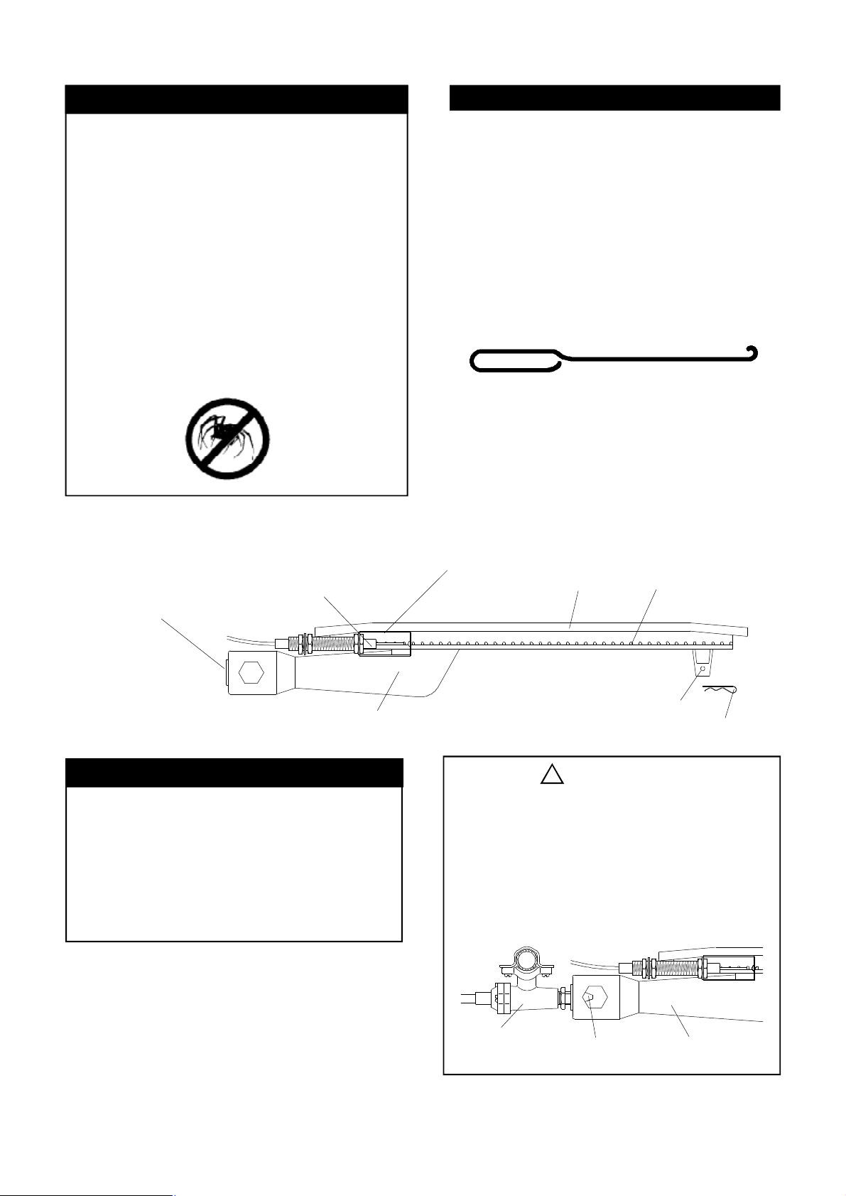
CAUTION: BEWARE OF FLASHBACK
Flashback Prevention
CAUTION: Spiders and small insects occa-
sionally spin webs or make nests in the grill
Burner Tubes during transit and warehousing.
These webs can lead to a gas flow obstruction which could result in a fire in and around
the Burner Tubes. This type of fire is known
as a "FLASHBACK" and can cause serious
damage to your grill and create an unsafe
operating condition for the user.
To reduce the chance of "FLASHBACK", you
must clean the burner tubes before assembling your grill, and at least once a month in
late summer or early fall when spiders are
most active. Also perform this Burner Tube
cleaning procedure if your grill has not been
used for an extended period of time.
Figure 1
To reduce the chance of "FLASHBACK" (see
CAUTION at left) clean the Burner Tubes and
Burners before fully assembling your grill.
Remove the Cotter Pin from the rear underside
of each Burner using a pair of long nose pliers.
Carefully lift each Burner up and away from the
Gas Valve Orifice, then refer to Figure 1 and
perform one of these three cleaning methods:
1.
Bend a stiff wire, (a lightweight coat hanger
works well) into a small hook as shown
below. Run the hook through the Burner Tube
and inside the Burner several times to remove
any debris.
Use a bottle brush with a flexible handle.
2.
Run the brush through the Burner Tube and
inside the Burner several times, removing any
debris.
3.
Use an air hose to force air through each
Burner Tube. The forced air should pass
debris or obstructions through the Burner and
out the Ports.
SPARK ELECTRODE
TO CLEAN BURNER TUBE,
INSERT HOOK HERE
ASSEMBLY
BURNER TUBE
Assembly Tips
Long nose pliers can be used to remove
•
Cotter Pin when cleaning the Burners
Use work gloves to protect your hands
•
Wear eye protection
•
When you have finished assembling your
•
grill we strongly urge that all Screws be
tightened with a Screwdriver
GAS COLLECTOR BOX
The location of the Burner Tube with respect to the Orifice is vital for safe operation. Check to ensure the Orifice is inside
the Burner Tube before using your gas grill.
See Figure 2. If the Orifice is not inside
the Burner Tube, lighting the Burner may
cause explosion and/or fire.
Figure 2
BURNER
!
WARNING
BURNER PORT
FOOT
COTTER PIN
GAS VALVE
ASSEMBLY
ORIFICE
BURNER TUBE
5
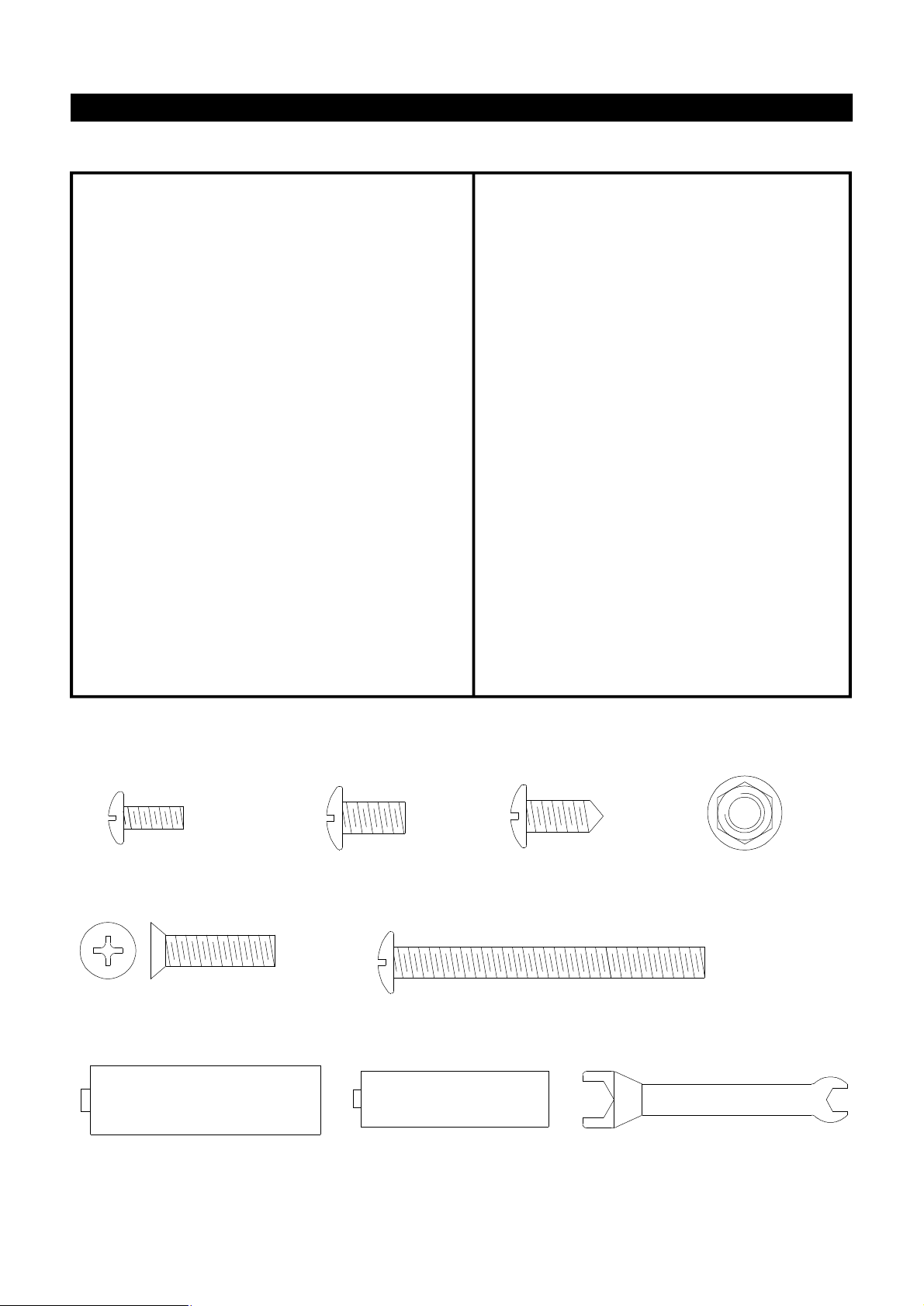
Contents for Hardware Pack/LPG (Part #P06020003A)
The following table illustrates a breakdown of the hardware pack. It highlights what components are used
in the various stages of assembly.
Ref.
S112G04401
S313G04061
S112G04081
S112G04081
S112G04081
S112G04081
S112G04081
S112G04081
S112G04081
S142G04161
S112G03081
S172G03081
P05301001A
P05301002A
Phillips Head Screw 1/4"x2"-1/2"
Flange Nut 1/4"
Phillips Head Screw 1/4"x1/2"
Phillips Head Screw 1/4"x1/2"
Phillips Head Screw 1/4"x1/2"
Phillips Head Screw 1/4"x1/2"
Phillips Head Screw 1/4"x1/2"
Phillips Head Screw 1/4"x1/2"
Phillips Head Screw 1/4"x1/2"
Countersink Flat Head Screw 1/4"x1"
Phillips Head Screw 3/16"x1/2"
Self-Tapping Screw 3/16"x1/2"
Battery/AA
Battery/AAA
Qty.Component
Purpose of Components
Install Cart Side Panel, Caster Seat and Cart
8
Bottom Shelf
8
Attach Caster Seat to Cart Bottom Shelf
8
Attach Cart Side Panel to Cart Rear Panel
4
Attach Door Handle Bracket to Doors
8
Attach Door Bracket to Cart Side Panel
4
Attach Tank Pull-Out Tray Assembly and Tank Pull-
6
Out Tray Stop to Cart Bottom Shelf
Attach Side Burner Frame and Side Shelf to Bowl
8
Attach Handle Brackets to Side Burner and Side
8
Shelf
Attach Bowl to Cart
6
Attach Tool Holder/Towel Rack to Side Burner
2
Frame/Side Shelf and side of Control Panel
Install Cart Towel Rack and Spice Basket
6
Power the Electric Ignitor
2
Power the Fuel Gauge
2
P05515005A
Phillips Head Screw 3/16"x1/2"
Qty. 2
Ref. # S112G03081
Countersink Flat Head Screw 1/4"x1"
Qty. 6
Ref. # S142G04161
Wrench
Tighten the Caster
1
LPG MODEL ONLY
Size and Quantity of each Hardware Piece:
Phillips Head Screw
1/4"x1/2"
Qty. 46
Ref. # S112G04081
Phillips Head Screw 1/4"x2-1/2"
Qty. 8
Ref. # S112G04401
Self-Tapping Screw
3/16"x1/2"
Qty. 6
Ref. # S172G03081
Flange Nut 1/4"
Qty. 8
Ref. # S313G04061
Battery/AA
Qty. 2
Ref. # P05301001A
Battery/AAA
Qty. 2
Ref. # P05301002A
6
Wrench (scale: 1/2)
Qty. 1
Ref. # P05515005A
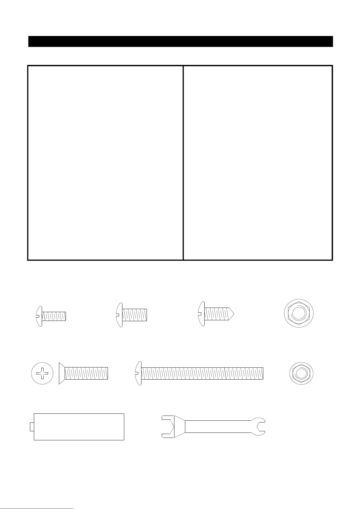
Contents for Hardware Pack/NG (Part #P06020004A)
The following table illustrates a breakdown of the hardware pack. It highlights what components are used
in the various stages of assembly.
Ref.
S112G04401
S313G04061
S112G04081
S112G04081
S112G04081
S112G04081
S112G04081
S112G04081
S142G04161
S112G03081
S112G03081
S313G03051
S172G03081
P05301001A
P05515005A
Phillips Head Screw 1/4"x2"-1/2"
Flange Nut 1/4"
Phillips Head Screw 1/4"x1/2"
Phillips Head Screw 1/4"x1/2"
Phillips Head Screw 1/4"x1/2"
Phillips Head Screw 1/4"x1/2"
Phillips Head Screw 1/4"x1/2"
Phillips Head Screw 1/4"x1/2"
Countersink Flat Head Screw 1/4"x1"
Phillips Head Screw 3/16"x1/2"
Phillips Head Screw 3/16"x1/2"
Flange Nut 3/16"
Self-Tapping Screw 3/16"x1/2"
Battery/AA
Wrench
Qty.Component
Purpose of Components
Install Cart Side Panel, Caster Seat and Cart
8
Bottom Shelf
8
Attach Caster Seat to Cart Bottom Shelf
8
Attach Cart Side Panel to Cart Rear Panel
4
Attach Door Handle Bracket to Doors
8
Attach Door Bracket to Cart Side Panel
4
Attach Side Burner Frame and Side Shelf to Bowl
8
Attach Handle Brackets to Side Burner and Side
8
Shelf
Attach Bowl to Cart
6
Attach Tool Holder/Towel Rack to Side Burner
2
Frame/Side Shelf and side of Control Panel
Attach NG Regulator Bracket to Cart Side Panel
2
2
Install the Cart Towel Rack and Spice Basket
6
Power the Electric Ignitor
2
Tighten the Caster
1
Phillips Head Screw
3/16"x1/2"
Qty. 4
Ref. # S112G03081
Countersink Flat Head Screw 1/4"x1"
Qty. 6
Ref. # S142G04161
Battery/AA
Qty. 2
Ref. # P05301001A
Phillips Head Screw
1/4"x1/2"
Qty. 40
Ref. # S112G04081
NG MODEL ONLY
Size and Quantity of each Hardware Piece:
Self-Tapping Screw
3/16"x1/2"
Qty. 6
Ref. # S172G03081
Phillips Head Screw 1/4"x2-1/2"
Qty. 8
Ref. # S112G04401
Wrench (scale: 1/2)
Qty. 1
Ref. # P05515005A
7
Flange Nut 1/4"
Qty. 8
Ref. # S313G04061
Flange Nut 3/16"
Qty. 2
Ref. # S313G03051

SOURCE04BLP & NG Parts Diagram
8

SOURCE04BLP & NG Parts List
DESCRIPTION
Lid
1
Lid Hinge Support, Left
2
Lid Hinge Support, Right
3
Temperature Gauge
4
Handle Bracket, Left
5
Handle Bracket, Right
6
Lid Handle
7
Handle Heat-Insulating Spacer
8
Protective Pad
9
Name Plate
10
Cooking Rack/Secondary
11
Cooking Grid/Large
12
Cooking Grid/Small
13
Flame Tamer/Stainless Steel
14
Smoker Drawer
15
Smoker Drawer Bracket, Front
16
Smoker Drawer Bracket, Rear
17
Burner/Main
18
Burner Air Shutter/Main (NG only)
18a
Smoker Burner
19
Burner Bracket
20
Gas Collector Box with Electrode
21
Electric Wire Set
22
Bowl Panel, Left
23
Bowl Panel, Right
24
Bowl Panel, Front
25
Bowl Panel, Rear
26
Bowl Wind Shield
27
Grease Tray Track, Left
28
Grease Tray Track, Right
29
Grease Tray Heat Shield, Upper
30
Grease Tray
31
Gas Valve/Manifold Assembly (LPG)
32
Gas Valve/Manifold Assembly (NG)
33
Electric Ignitor, 4-Port
34
Electric Ignitor, 2-Port
Control Panel (LPG)
35
Control Panel (NG)
Control Knob
36
Control Knob Seat
37
Back Burner Assembly (LPG)
38
Back Burner Assembly (NG)
Back Burner Frame
39
PART#
Y0110021
P03320003K
P03320004K
P00601171A
P00301026E
P00302026E
P00205045B
P06801008A
P05518002I
P00416001C
P01517002B
P01604001B
P01604003B
P01708001B
P06701006A
P06703001A
P06703002A
P02001062E
P05524006A
P02008002A
P02213024A
P02609004B
P02615017A
P00705057G
P00706057G
P00738096C
P00725146C
P0071608FC
P05330001E
P05330002E
P06904003C
P0270605CC
Y0060111
Y0060112
P02502024C
P02502012C
P02910061B
P02910061G
P03411073L
P03415024A
Y0030012
Y0030013
P02011007E
QTYREF#
1
1
1
1
3
3
1
6
6
1
1
2
1
4
1
1
1
4
4
1
1
5
1
1
1
1
1
1
1
1
1
1
1
1
1
1
1
1
7
7
1
1
1
9

SOURCE04BLP & NG Parts List
DESCRIPTION
40
Back Burner Extension Tube
41
Back Burner Wind Shied
42
Cart Side Panel, Left (LPG only)
43
Cart Side Panel, Left (NG only)
44
Cart Side Panel, Right
45
Cart Bottom Shelf (LPG only)
46
Cart Bottom Shelf (NG only)
47
Cart Rear Panel
48
Door Bracket
49
Door, Left
50
Door, Right
51
Door Trim Plate, Left
52
Door Trim Plate, Right
53
Door Magnet
54
Door Handle Bracket, Left
55
Door Handle Bracket, Right
56
Door Handle
57
Door Handle Heat-Insulating Spacer
58
Caster, 3 in., with Brake
59
Caster Seat Set
60
Tank Pull-Out Tray Assembly (LPG only)
61
Side Burner Frame
62
Side Shelf, Right
63
Side Shelf Handle
64
Side Burner Lid
65
Side Burner Lid Knob
66
Side Burner Lid Bracket
67
Side Burner Pot Support
68
Side Burner Electrode
69
Side Burner Gas Valve Assembly (LPG)
Side Burner Gas Valve Assembly (NG)
70
Side Burner with Brass Ring
71
Side Burner Bracket
72
Side Burner Connection Hose (LPG)
Side Burner Connection Hose (NG)
73
Tool Holder/Towel Rack
74
Tool Hook
75
Regulator with Hose (LPG)
76
Hose/LPG/Protective Plate
77
Regulator Assembly (NG)
78
Side Burner Extension Hose (NG only)
79
Hose, 12 ft. (NG)
80
Cart Spice Basket
81
Cart Towel Rack Bracket
82
Cart Towel Rack
83
Lighting Stick
---
Hardware Pack (LPG)
---
Hardware Pack (NG)
---
Owner's Manual
---
Grill Cover
---
Rotisserie Assembly
PART#
P03701002A
P06906008C
P07602002A
P07602003A
P07603002A
P01009001C
P01009002C
P07701023A
P03302008C
P04302014A
P04303017A
P07506004A
P07507004A
P05523002K
P00301036E
P00302036E
P00205048B
P06801009A
P05106003D
Y0260018
Y0340017
P01108002B
P01107003B
P00205046B
P01127001A
P00215001B
P03326001A
P00814001D
P02607003C
Y0060113
Y0060114
P02002005G
P02215025A
P03705008H
P03705008I
P05514004A
P05514005A
P03601011A
P05535001L
Y0080015
P03705010A
P03703001A
P05203001A
P05212008A
P05209003A
P05313023B
P06020003A
P06020004A
P80157002A
P07002005B
Y0250052
QTYREF#
1
1
1
1
1
1
1
1
1
1
1
1
1
2
2
2
2
4
4
1
1
1
1
2
1
1
2
1
1
1
1
1
1
1
1
2
5
1
1
1
1
1
1
1
1
1
1
1
1
1
1
10
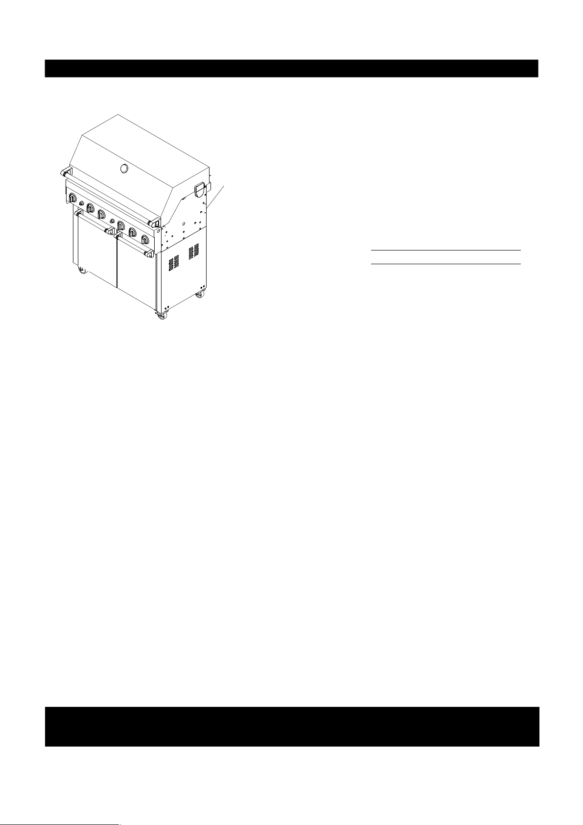
SOURCE04BLP & NG Parts List
CSA label located here
Record your grill Model Number and Serial Number
below for future reference.
MODEL NUMBER
SERIAL NUMBER
For the repair or replacement parts you need:
Call 8:00am - 4:30 pm CST, Monday through Friday at 1-877-934-7455.
To make sure you obtain the correct replacement part(s) for your Gas Grill, please refer to the parts list. The
following information is required to assure you receive the correct part(s):
1. Model and Serial Number (see CSA label on grill)
2. Part Number
3. Description
4. Quantity of part(s) needed
Please allow sufficient time to process and ship.
IMPORTANT: Keep this Owner's Manual for convenient referral and for part(s) replacement.
IMPORTANT: Use only factory authorized parts. The use of any part that is not factory authorized can be
dangerous. This will also void your warranty.
Grill Information Center: If you have questions about assembly or grill operation, or
if there are damaged or missing parts when you unpack this unit from the shipping box, call us
8:00 am - 4:30 pm CST, Monday through Friday at: 1-877-934-7455
11
 Loading...