

Grand Hall B3816blp, B3816ang Owner's Manual

Operator's Manual
Liquid Propane Gas (LPG) Grill
Models B3816ALP, B381 6BLP , BAI16A LP & BAI16 BLP
Natural Gas (NG ) Grill
Models B3816 ANG , B3 816BN G, B AI 16AN G & BAI 16 BNG
B3816ALP/NG BAI16ALP/NG
B3816BLP/NG BAI16BLP/NG
Grill Information Center:
FREE HELP
FROM THE GRILL EXPERTS
Barbeques Galore is the expert on this
product and trained to help you with:
Assembly Questions
Ÿ
Grill Operation
Ÿ
Replacement of Damaged or Missing parts
Ÿ
visit www.grandhall.com or call:
1-800-474-5587
Monday - Friday 8:00am-4:30pm PST
IMPORTANT:
NOTE TO ASSEMBLER / INSTALLER:
Ÿ
Leave this manual with the consumer.
NOTE TO CONSUMER:
Ÿ
Keep this manual for future reference.
RECORD YOUR SERIAL #
Ÿ
__________________
(see silver CSA label on main body of grill)
! !
Failure to comply with these instructions could
Ÿ
result in a fire or explosion that could cause
serious bodily injury, death or property damage.
Whether this grill was assembled by you or
Ÿ
someone else, you must read this entire manual
before using your grill to ensure the grill is
properly assembled, installed and maintained.
Use your grill at least 3 feet away from any
Ÿ
wall or surface. Use your grill at least 3 feet
away from combustible objects that can melt or
catch fire such as vinyl or wood siding, fences
and overhangs or sources of ignition including
pilot lights on water heaters and live electrical
appliances.
THIS GAS APPLIANCE IS DESIGNED FOR
Ÿ
OUTDOOR USE ONLY.
Never use your gas grill in a garage, porch,
Ÿ
shed, breezeway or any other enclosed area.
Never obstruct the flow of ventilation air
Ÿ
around your gas grill housing.
Never disconnect the gas regulator or any gas
Ÿ
fitting while your grill is lit. A lit grill can ignite
leaking gas and cause a fire or explosion which
could result in property damage, personal injury
or death.
WARNING
Manual # P80151152A - Date:2016/01/20
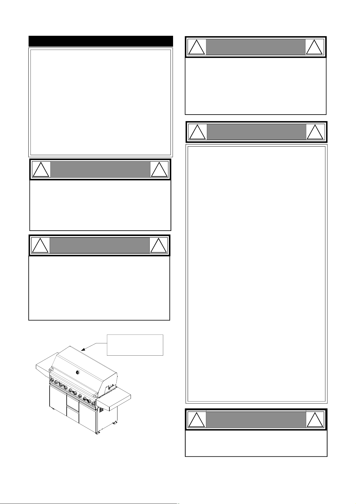
Table of Contents
Primary Safety Warnings............................1-3
Pre-Assembly Instructions...............................3
Part Diagrams and Lists............................4-15
Assembly Instructions.................................16-23
Use & Care Instructions:
• Gas Safety and Leak Tests..............24-27
• Natural Gas Connection............................28
• Lighting Instructions...............................29-30
• Troubleshooting...........................................31
• Rotisserie Instruction..............................32-34
Cleaning and Maintenance........................35-36
Cooking Guide............................................A1-A5
Frequently Asked Questions...................A6-A7
Warranty...........................................Back Cover
!
•
This appliance, when installed, must be electrically grounded in accordance with local codes
or, in the absence of local codes, with the
National Electrical Code, ANSI/NFPA 70, or the
Canadian Electrical Code, CSA C22.1.
•
Keep any electrical supply cord and the fuel
supply hose away from any heated surfaces.
WARNING
!
! !
1.
Do not store or use gasoline or other
WARNING
flammable liquids or vapors in the
vicinity of this or any other
appliances.
An LP cylinder not connected for
2.
use shall not be stored in the vicinity
of this or any other appliance.
! !
LPG models must be used with Liquid Propane
•
Gas and the regulator assembly supplied. Natural
Gas models must be used with Natural Gas only.
Any attempt to convert the grill from one fuel type
to another is extremely hazardous and will void the
warranty.
Keep gas regulator hose away from hot grill sur-
•
faces and dripping grease. Avoid unnecessary twisting of hose. Visually inspect hose prior to each use
for cuts, cracks, excessive wear or other damage.
If the hose appears damaged do not use the gas
grill. Call 1-800-474-5587 for a certified replacement hose.
WARNING
!
DANGER
If you smell gas:
Shut off gas to the appliance.
1.
Extinguish any open flame.
2.
Open lid.
3.
If odor continues, keep away from
4.
the appliance and immediately call
your gas supplier or your fire
department.
CSA label located on
the Rotisserie Burner
Wind Shield.
California Proposition 65
•
!
Combustion byproducts produced when using this
product contain chemicals known to the State of California to cause cancer, birth defects, or other reproductive harm.
Brass components on the grill, such as hose fittings,
propane cylinder valves (sold separately) and burner
valve stems, contain lead which is known to the State
of California to cause cancer, birth defects, or other
reproductive harm.
Never use charcoal or lighter fluid in this gas grill.
•
Failure to comply with these instructions could result
in a grease fire or explosion that could cause serious
bodily injury, death or property damage.
Before each use of your grill: Inspect the Grease Tray,
•
Grease Tray Heat Shield and inside of the Grill Bowl to
be sure there is no excessive grease and debris
buildup. Clean the Grease Tray, Grease Tray Heat
Shield and inside of the Grill Bowl frequently to eliminate grease/debris build-up and to prevent grease
fires. Failure to comply with these instructions could
result in a grease fire and even a subsequent explosion that could cause serious bodily injury, death or
property damage.
! !
Never cover or wrap the Cooking Grids, bottom
of the Grill Bowl, Grease Tray with aluminum foil
or any other material that will absorb grease.
2
WARNING
Pre-Assembly Instructions For Your Safety
! !
Failure to comply with these instructions may result
in a hazardous situation which, if not avoided, may
result in injury.
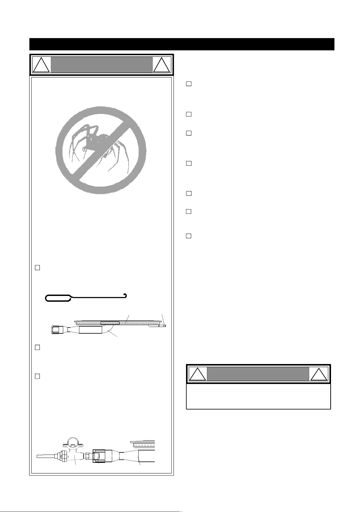
Spiders and small insects can spin webs and nest
in the grill Burner Tubes during transit and warehousing which can lead to a gas flow obstruction
resulting in a fire in and around the Burner Tubes.
This type of "FLASHBACK FIRE" can cause serious
grill damage and create an unsafe operating condition for the user.
To reduce the chance of FLASHBACK FIRE
you must clean the Burner Tubes as follows
before initial use. Also do this at least once a
month in summer and fall or whenever spiders are
active in your area, and if your grill has not been
used for an extended period of time.
CAUTION
PRE-ASSEMBLY
Read and perform the following pre-assembly instructions:
Tools Required for Assembly:
protective work gloves
•
protective eyewear
•
Phillips Head Screwdriver
•
You will need assistance from another person to handle
the grill head and other large, heavy parts.
Open lid of shipping carton. Remove top sheet of
cardboard and packing materials. Lay cardboard sheet
on floor and use as a work surface to protect floor and
grill parts from scratches.
You may slice the carton front corners with a utility knife
to lay open the carton front panel. This allows you to
raise the Lid and remove the components packed inside,
making it easier to lift.
Remove the screws from the rear of each Main Burner
1.
using a Phillips Head Screwdriver or wrench.
Carefully lift each Burner up and away from the Gas
2.
Valve Orifice.
Check and clean Burner/Venturi Tubes for insects
3.
and insect nests. A clogged tube can lead to a fire
beneath the grill.
Refer to the figure below and perform one of these
4.
3 cleaning methods:
METHOD 1: Bend a stiff wire or wire coat hanger
into a small hook as shown and run the hook
through the Burner Tube and inside the Burner
several times to remove debris.
TO CLEAN BURNER TUBE,
INSERT HOOK
HERE
9
METHOD 2: Use a bottle brush with a flexible
handle and run the brush through the Burner
Tube and inside the Burner several times to
remove any debris.
METHOD 3: Use an air hose to force air through
each Burner Tube. The forced air should pass
debris or obstructions through the Burner and out
the Ports.
For safe operation ensure the Gas Valve Assembly Orifice is inside the Burner Tube before using
your grill. (See figure). If the Orifice is not inside
the Burner Tube, lighting the Burner may cause
explosion and/or fire resulting in serious bodily
injury and/or property damage.
Burner Port
Burner Tube
Foot
Use the Hardware and Part Diagrams to ensure all items
are included and free of damage.
Do not throw away the bags of hardware that are included with boxed parts. These are required for assembly.
Do not assemble or operate the grill if it appears
damaged. If there are damaged or missing parts when
you unpack the shipping box or you have questions during the assembly process call 1-800-474-5587 M-F 8AM4:30PM PST for assistance.
Grill Installation Codes
The installation must conform with local codes or, in the
absence of local codes, with either the National Fuel Gas
Code, ANSI Z223.1/NFPA 54, Natural Gas and Propane
Installation Code, CSA B149.1, or Propane Storage and
Handling Code, B149.2.
WARNING: Grease can get very hot. Always handle the Grease
Tray with a flame retardant BBQ mitt. Before removing the
Tray, always be sure that the grill has properly cooled. Be
aware that the Tray does contain grease and be extremely
careful when removing the Tray to prevent spillage. Failure to
follow these instructions could cause serious bodily injury or
property damage.
!
When using electrical appliances, basic safety
precautions should always be used.
CAUTION
WARNING
!
Gas Valve Assembly
Orifice
Burner Tube
3
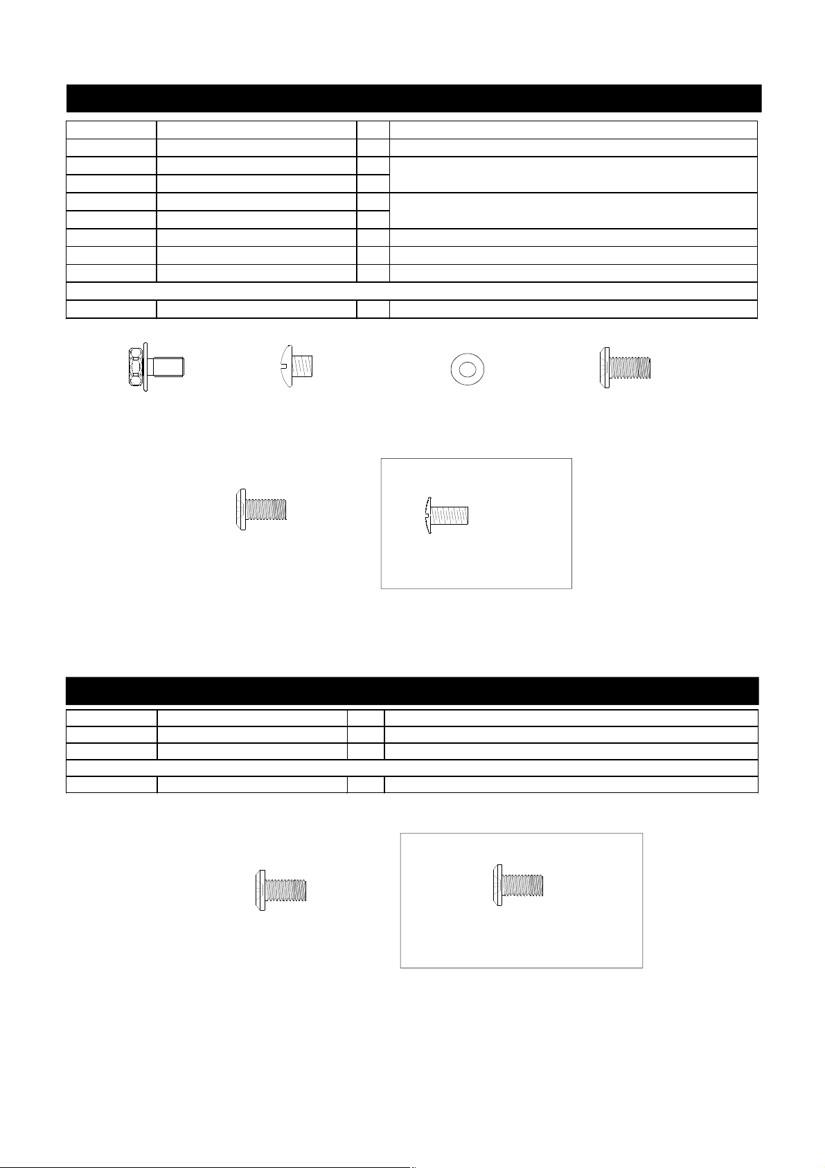
Hardware Parts List for Models B3816ALP/NG & B3816BLP/NG
Already installed in the Rear Panel of the Bowl Frame
PART # PART DESCRIPTION QTY PURPOSE OF PART
P06013026A Hardware Pack 1 For use in assembly of B3816ALP/NG & B3816BLP/NG Models
S162G04081Hex Head Screw 1/4"x1/2" 5
S112G04041Phillips Head Screw 1/4"x1/4" 2
S112G04041Phillips Head Screws 1/4"x1/4" 2
S411G04011
Plain Washer 1/4" 2
S182G03061Pan Head Screw 3/16"x3/8" 2 Install the LP Regulator Brackets (for B3816BLP Models)
S182G03061Pan Head Screw 3/16"x3/8" 3 Install the Tank Tray Set (for B38126LP & B3816BLP Models)
S182G04081Pan Head Screw 1/4"x1/2" 13 Install Bowl Side Trim Panel (for B3816BLP/NG Models)
Already installed in the Left Cart Side Panel Trim Plate
S112G03081Phillips Head Screw 3/16"x1/2" 6
Install Bowl to Cart (for B3816ALP/NG Models)
Install Transformer Bracket to the Left Panel of the Bowl Frame
(for B3816BLP/NG Models)
Install Left Cart Side Panel Trim Plate (for B3816ALP/NG Models)
Hex Head Screw
1/4"x1/2"
Qty. 5
Part # S162G04081
*One Battery/AA included in the Hardware Pack
Phillips Head Screw
1/4"x1/4"
Qty. 4
Part # S112G04041
Pan Head Screw
1/4"x1/2"
Qty. 13
Part # S182G04081
Plain Washer 1/4"
Qty. 2
Part # S411G04011
Already installed in the Left Cart
Side Panel Trim Plate
Phillips Head Screw 3/16"x1/2"
Qty. 6
Part # S112G03081
Pan Head Screw
3/16"x3/8"
Qty. 5
Part # S182G04061
Hardware Parts List for B3816ALP/NG Cart Model
PART # PART DESCRIPTION QTY PURPOSE OF PART
P06030028A Hardware Pack 1 For use in assembly B3816ALP/NG Cart Models
S182G04081Pan Head Screw 1/4"x1/2" 12 Install Side Shelves
S182G04081Pan Head Screw 1/4"x1/2" 1 Install the Side Burner Lid Chain
Pan Head Screw 1/4"x1/2"
Qty. 12
Part # S112G04081
Already installed in the Rear Panel of the
Bowl Frame
Phillips Head Screw 1/4"x1/2"
Qty. 1
Part # S112G04081
4
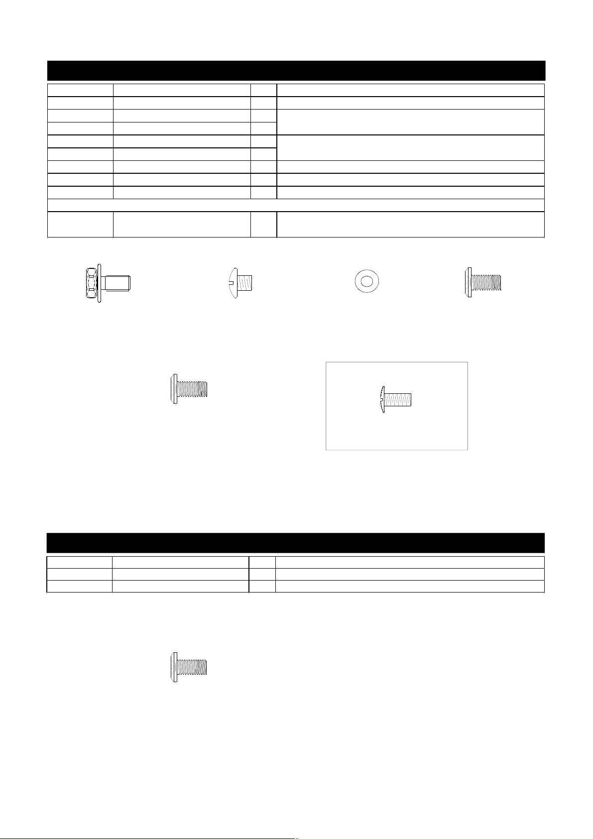
Hardware Parts List for Models BAI16ALP/NG & BAI16BLP/NG
PART # PART DESCRIPTION QTY PURPOSE OF PART
P06013027A Hardware Pack 1 For use in assembly of BAI16ALP/NG & BAI16BLP/NG Models
S162G04081Hex Head Screw 1/4"x1/2" 6
S112G04041Phillips Head Screw 1/4"x1/4" 2
S112G04041Phillips Head Screws 1/4"x1/4" 2
S411G04011
Plain Washer 1/4" 2
S182G03061Pan Head Screw 3/16"x3/8" 2 Install the LP Regulator Brackets (for BAI16BLP Model)
S182G03061Pan Head Screw 3/16"x3/8" 3 Install the Tank Tray Set (for BAI16ALP & BAI16BLP Model)
S182G04081Pan Head Screw 1/4"x1/2" 4 Install Rear Trim Panel (for BAI16BLP/NG Models)
Already installed in the Left and Right Cart Side Panel Trim Plates
S112G03081Phillips Head Screw 3/16"x1/2" 12
Install Bowl to Cart (for BAI16ALP/NG Models)
Install Transformer Bracket to the Left Panel of the Bowl Frame
(for BAI16BLP/NG Models)
Install Left and Right Cart Side Panel Trim Plates (for
BAI16ALP/NG Models)
Hex Head Screw
1/4"x1/2"
Qty. 6
Part # S162G04081
Pan Head Screw 1/4"x1/2"
Qty. 4
Part # S182G04081
*Two Batteries/AA included in the Hardware Pack
Phillips Head Screw
1/4"x1/4"
Qty. 4
Part # S112G04041
Plain Washer 1/4"
Qty. 2
Part # S411G04011
Already installed in the Left and
Right Cart Side Panel Trim Plates
Phillips Head Screw 3/16"x1/2"
Qty. 12
Part # S112G03081
Pan Head Screw
3/16"x3/8"
Qty. 5
Part # S182G04061
Hardware Parts List for BAI16ALP/NG Cart Model
PART # PART DESCRIPTION QTY PURPOSE OF PART
P06030028A Hardware Pack 1 For use in assembly B3816ALP/NG Cart Models
S182G04081Pan Head Screw 1/4"x1/2" 12 Install Side Shelves
Pan Head Screw 1/4"x1/2"
Qty. 12
Part # S112G04081
5
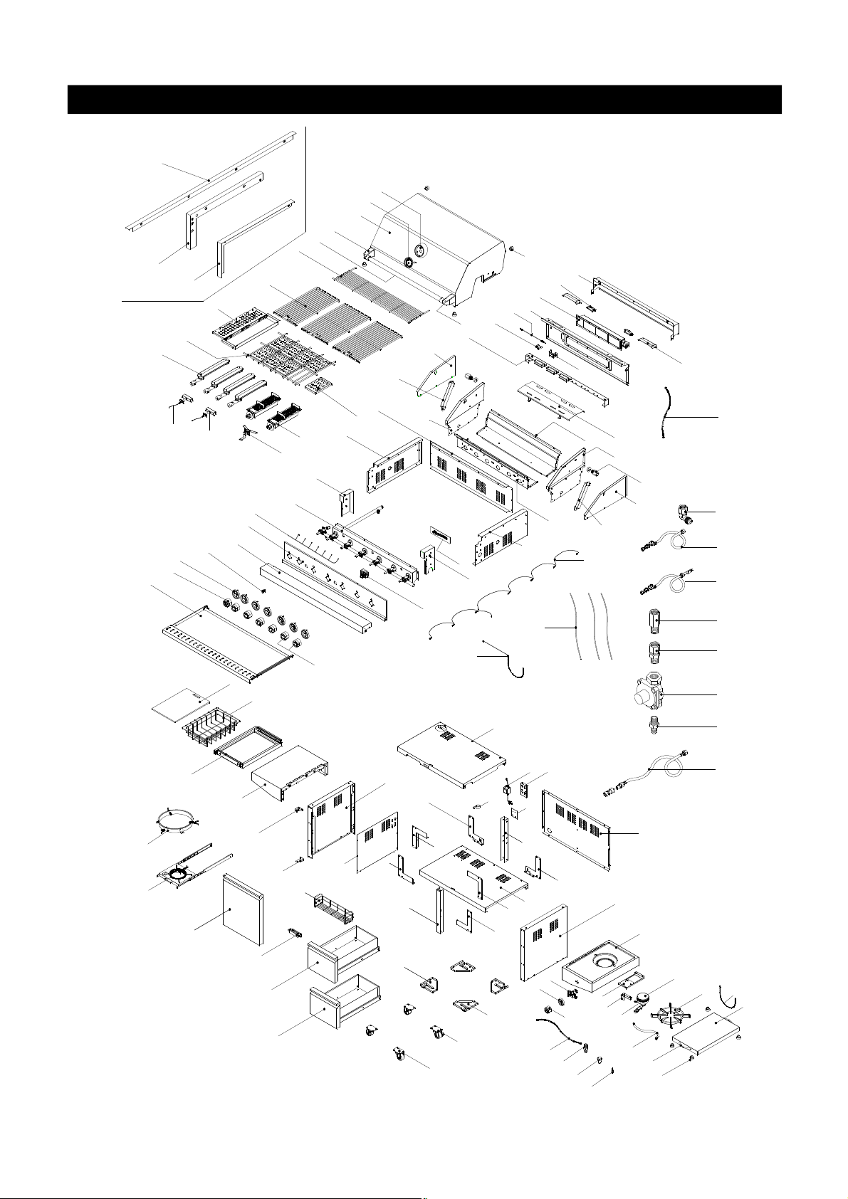
Parts Diagram for Models B3816ALP/NG & B3816BLP/NG
B3
5
6
1
2
3
B1
14
11
B2
13
8
9
4
21
18
23
A7
A6
A2
7
A1
A4
A3
A8
A5
38
37
55
36
87
35
16
34B
34A
89
86
32
88
17
31
15
29
83
26
12
28
50
25C
60
33
10
47
30
54C
48
27
53
54A
91
25A
54B
25B
90
24
22
25D
19
39
20
40
41A
41B
42
43
44
45
46
56a
56b(Optional)
67
63
68
65
66
64
73
74
59
69
57
51
77A
81
52
75
80
79A
77B
78
96
79
71
61
72
70
60
62
49
58
84
85
92
93
59
83
95
94
76
82
6

Parts List for Model B3816ALP/NG & B3816BLP/NG
44
Regulator / NG
P03628001B
P03628001B
1
KEY DESCRIPTION B3816ALP/NG PART# B3816BLP/NG PART# QTY
1 Lid Assembly Y0130032 Y0130032 1
2 Lid Handle Bracket P00303016E P00303016E 2
3 Lid Handle P00205120B P00205120B 1
4 Lid Handle Heat-Insulating Spacer P06801002A P06801002A 2
5 Temperature Gauge Seat P00614015A P00614015A 1
6 Temperature Gauge P00601251A P00601251A 1
7 Protective Pad P05518002I P05518002I 4
8 Cooking Rack/Secondary P01516035B P01516035B 1
9 Cooking Grid/Large P01606043B P01606043B 3
10 Name Plate P00407014C P00407014C 1
11 Flame Tamer/Rack P01720042B P01720042B 1
12 Flame Tamer/Ceramic P01804002A P01804002A 8
13 Smoker Box P06701020A P06701020A 1
14 Burner/Main P02003049B P02003049B 4
15 Infrared Burner P02005020A P02005020A 2
16 Gas Collector Box with Electrode P02610020A P02610020A 2
17 Infrared Burner Dual Electrode P02625002C P02625002C 1
18 Bowl Side Panel/Trim Plate/Left P07514065A P07514065A 1
19 Bowl Side Panel/Trim Plate/Right P07514066A P07514066A 1
20 Lid Hinge with Nut P05511006A P05511006A 2
21 Burner Bracket P02206314A P02206314A 1
22 Grease Draining Tray Heat Shield P06904069C P06904069C 1
23 Lid Spring,Left P05551005M P05551005M 1
24 Lid Spring,Right P05551006M P05551006M 1
25A Grill Bowl Panel, Front P00763206C P00763206C 1
25B Grill Bowl Panel, Rear P00760336C P00760336C 1
25C Grill Bowl Panel, Left P00761376C P00761376C 1
25D Grill Bowl Panel, Right P00762366C P00762366C 1
26 Body Panel, Left P00742036C P00742036C 1
27 Body Panel, Right P00746036C P00746036C 1
28 Bowl Panel, Rear P00737616C P00737616C 1
29 Bowl Frame Bracket,Left P03304075C P03304075C 1
30 Bowl Frame Bracket,Right P03304076C P03304076C 1
31 Gas Valve/Manifold Assembly-LP Y0060850 Y0060850 1
Gas Valve/Manifold Assembly-NG Y0060851 Y0060851 1
32 Control Knob Wire Assembly P05383008B P05383008B 1
33 Electric Ignitor, 6-Ports P02502305C P02502305C 1
34A Control Panel P02916173A P02916173A 1
34B Control Panel,Upper P02916183A P02916183A 1
35 Lighting Switch P05360004B P05360004B 1
36 Control Knob Seat with LED Light P03445014A P03445014A 7
37 Control Knob for Main Burner P034265621 P034265621 5
38 Grease Tray Assembly Y0270006 Y0270006 1
39 Extension Tube P03701011A P03701011A 1
40 Extension Fitting for Manifold P03907012A P03907012A 1
41A Regulator with Hose / LPG P03624010A N/A 1
41B Regulator with Hose and Connector (LPG) N/A P03624011A 1
42 Extension Fitting for Manifold (NG only) P03901015A P03901015A 1
43 Extension Fitting - Outlet (NG only) P03901013A P03901013A 1
45 Extension Fitting - Inlet (NG only) P03901017A P03901017A 1
46 Hose, 12 FT. NG (Sold Separately) P03704001A P03704001A 1
7

Parts List for Models B3816ALP/NG & B3816BLP/NG
KEY DESCRIPTION B3816ALP/NG PART# B3816BLP/NG PART# QTY
47 Lighting Stick Assembly P05507140M P05507140M 1
48 Cart Top Shelf P01010040C N/A 1
49 Cart Bottom Shelf P01010044C N/A 1
50 Cart Side Panel,Left P07602027A N/A 1
51 Cart Side Panel,Right P07603030A N/A 1
52 Cart Rear Panel P07701079A N/A 1
53 Transformer P05374022B P05374022B 1
54A Transformer Connecting Bracket P03328082C P03328082C 1
54B Transformer Bracket (bulit in model only) N/A P03328057A 1
54C Cord Clip P055530033 P055530033 1
55 Electric Wires Set/Electrode P02615046D P02615046D 1
56a Tank Tray Set Y0340055 Y0340055 1
56b Tank Tray Assembly (Optional) Y0340022 N/A 1
57 Drawer Bracket,Front P03304050C N/A 1
58 Drawer Bracket,Rear P03304051C N/A 1
59 Cart Bracket Panel,Left Bottom P03331011F N/A 2
60 Cart Bracket Panel,Right Bottom P03331012F N/A 2
61 Cart Bracket Panel,Left Top P03331013F N/A 1
62 Cart Bracket Panel,Right Top P03331014F N/A 1
63 Door Hinge Bracket -Left Top P03314050C N/A 1
64 Door Hinge Bracket-Left Bottom P03314037C N/A 1
65 Drawer Assembly,Upper Y0420012 N/A 1
66 Drawer Assembly,Lower Y0420013 N/A 1
67 Door P04302049A N/A 1
68 Door Magnet P05323007M N/A 1
69 Caster Seat,Left Front & Right Rear P05327062H N/A 2
70 Caster Seat,Right Front & Left Rear P05327063H N/A 2
71 Caster, 2.5 in., without Brake/Front P05117007E N/A 2
72 Caster, 2.5 in., with Brake/Rear P05110001E N/A 2
73 Spice Basket P05203001A N/A 1
74 Cart Side Panel,Left/Trim Plate P07509010A N/A 1
75 Side Burner Body P01108014B N/A 1
76 Side Burner Bracket Assembly P02215105A N/A 1
77A Side Burner P02004040B N/A 1
77B Side Burner Cap P02013059E N/A 1
78 Pot Support P00815008A N/A 1
79 Side Burner Lid P0011558AA N/A 1
79A Protective Pad P05518002I N/A 4
80 Side Burner Lid Handle P00210006A N/A 2
81 Side Burner Connection Hose P03710003F N/A 1
82 Side Burner Orifice Bracket P03317002A N/A 1
83 Control Knob for Infrared Burner/Side Burner P034265721 P034265721 2
84 Control Knob Seat for Side Burner
85 Side Burner Gas Valve P03218129G N/A 1
86 Side Shelf,Left P01106046B N/A 1
87 Side Shelf Spice Basket Assembly P05204071G N/A 1
88 Side Shelf Spice Basket P05204072G N/A 1
89 Cutting Board P02401004A N/A 1
90 Electric Wires Set P02615132A P02615132A 1
91 Lamp Wires Set P02615198A P02615198A 1
P03415034A
N/A 1
8

Parts List for Models B3816ALP/NG & B3816BLP/NG
KEY DESCRIPTION B3816ALP/NG PART# B3816BLP/NG PART# QTY
92 Side Burner Orifice Connection Hose P03701028F P03701028F 1
93 Extension Fitting for Side Burner P03901038A N/A 1
94 Side Burner Electrode P02607058M N/A 1
Side Burner Orifice-LP P06533018A N/A 1
95
Side Burner Orifice-NG P06533019A N/A 1
96 Side Burner Lid Chain P05522001A N/A 1
A1 Back Burner Wind Shield P06906109C P06906109C 1
A2 Back Burner Frame P0075825BC P0075825BC 1
Back Burner Assembly-LP Y0030030 Y0030030 1
A3
Back Burner Assembly-NG Y0030031 Y0030031 1
A4 Lamp P05352032B P05352032B 2
A5 Lamp Cover P05352004E P05352004E 2
A6 Back burner Thermocouple P05305068A P05305068A 1
A7 Back Burner Electrode P02614015C P02614015C 1
A8 Back Burner Thermocouple Bracket P03328090C P03328090C 1
B1 Trim Panel, Left N/A P07505002A 1
B2 Trim Panel, Right N/A P07504002A 1
B3 Trim Panel, Rear N/A P07515031A 1
Rotisserie Assembly
Hardware Pack (Grill Head)
Hardware Pack (Cart Model)
Operator's Manual
Y0250222 Y0250222
P06013026A P06013026A 1
P06030028A N/A
P80151152A P80151152A
1
1
1
9
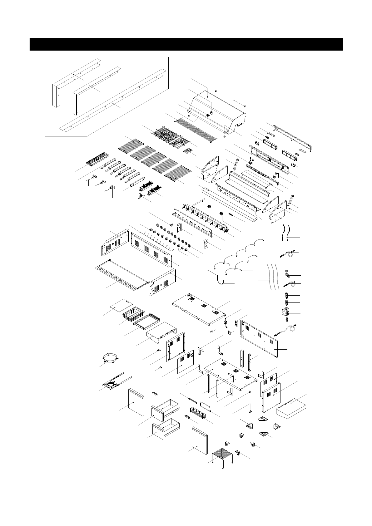
Parts Diagram for Models BAI16ALP/NG & BAI16BLP/NG
B1
B2
B3
9A
11
13
15
58
41
86
59a
59b(Optional)
92
17
34
36
38
42
85
84
83
68
71
70A
8
16
18
53
66
90
1
5
6
2
3
9B
10
19
21
28
12
57A
35
37
36
40
39
62
52
78
65
60
63
79
73
56D
69
A9
26A
57B
64
80
7
A1
A5
A4
A3
4
A7
A6
A2
A8
24
25
27B
26B
23
20
27A
29
31
32
33
88
87
51
56C
63
67
74
89
56A
56B
61
22
43
30
44
45
46
47
48
49
50
55
62
91
54
82
70B
10
75
72
81
77
76

Parts List for Models BAI16ALP/NG & BAI16BLP/NG
4
Lid Handle Heat-Insulating Spacer
P06801002A
P06801002A
2
30
Regulator with Hose and Connector/ LPG
P03624011A
131Electric Ignitor, 4-Ports
P02502184C
P02502184C
2
KEY DESCRIPTION BAI16ALP/NG PART# BAI16BLP/NG PART# QTY
1 Lid Assembly Y0130015 Y0130015 1
2 Lid Handle Bracket P00303016E P00303016E 2
3 Lid Handle P00205064B P00205064B 1
5 Temperature Gauge Seat P00614015A P00614015A 1
6 Temperature Gauge P00601251A P00601251A 1
7 Protective Pad P05518002I P05518002I 4
8 Cooking Rack/Secondary P01518007B P01518007B 1
9 Flame Tamer/Rack(Large) P01720042B P01720042B 1
10 Flame Tamer/Rack(Small) P01720043B P01720043B 1
11 Flame Tamer/Ceramic P01804002A P01804002A 12
12 Cooking Grid - Large P01606044B P01606044B 4
13 Cooking Grid - Small P01606045B P01606045B 1
14 Smoker Box P06701020A P06701020A 1
15 Burner/Main P02003049B P02003049B 6
16 Infrared Burner P02005020A P02005020A 2
17 Gas Collector Box with Electrode P02610020A P02610020A 3
18 Infrared Burner Dual Electrode P02625002C P02625002C 1
19 Bowl Side Panel/Left P00761376C P00761376C 1
20 Bowl Side Panel/Right P00762366C P00762366C 1
21 Bowl Side Panel/Trim Plate/Left P07514065A P07514065A 1
22 Bowl Side Panel/Trim Plate/Right P07514066A P07514066A 1
23 Lid Hinge with Nut P05511006A P05511006A 2
24 Burner Bracket P02216044A P02216044A 1
25 Grease Tray Heat Shield P06904070C P06904070C 1
26A Lid Spring,Left P05551001M P05551001M 1
26B Lid Spring,Right P05551002M P05551002M 1
27A Bowl Panel, Front P00763216C P00763216C 1
27B Bowl Panel, Rear P00760346C P00760346C 1
28 Control Panel, Upper P02916203A P02916203A 1
29 Name Plate P00407014C P00407014C 1
N/A
32 Gas Valve/Manifold Assembly-LP Y0060852 Y0060852 1
Gas Valve/Manifold Assembly-NG Y0060853 Y0060853 1
33 Control Panel P02916193A P02916193A 1
34 Lighting Switch P05360004B P05360004B 1
35 Control Knob Seat with LED Light P03445014A P03445014A 10
36 Control Knob for Main Burner/ Back Burner P034265621 P034265621 8
37 Control Knob for Infrared Burner P034265721 P034265721 2
38 Body Panel,Left P00742036C P00742036C 1
39 Body Panel,Right P00746036C P00746036C 1
40 Body Panel,Rear P00760346C P00760346C 1
41 Grease Tray Assembly Y0270022 Y0270022 1
42 LED Wire Assembly P05383023B P05383023B 1
43 Extension Tube P03701011A P03701011A 2
44 Extension Fitting for Manifold (LPG only) P03902016A P03902016A 1
45 Regulator with Hose / LPG P03624010A N/A 1
46 Extension Fitting for Manifold (NG only) P03901015A P03901015A 1
47 Extension Fitting - Outlet (NG only) P03901013A P03901013A 1
11

Parts List for Models BAI16ALP/NG & BAI16BLP/NG
48
Regulator / NG
P03628001B
P03628001B
149Extension Fitting - Inlet (NG only)
P03901017A
P03901017A
150Hose, 12 FT. NG (Sold Separately)
P03704001A
P03704001A
151Cart Top Shelf
P01010039C
152Cart Bottom Shelf
P01010038C
1
KEY DESCRIPTION BAI16ALP/NG PART# BAI16BLP/NG PART# QTY
N/A
N/A
53 Cart Side Panel,Left P07602027A N/A 1
54 Cart Side Panel,Right P07603030A N/A 1
55 Cart Rear Panel P07701078A N/A 1
56A Transformer P05374022B P05374022B 1
56B Transformer Bracket N/A P03328057A 1
56C Transformer Connecting Bracket P03328082C P03328082C 1
54D Cord Clip P055530033 P055530033 1
57A Bowl Frame Bracket,Left P03304077C P03304077C 1
57B Bowl Frame Bracket,Right P03304078C P03304078C 1
58 Electric Wires Set/ Electrode P02615109D P02615109D 1
59a Tank Tray Set Y0340055 Y0340055 1
59b Tank Tray Assembly (Optional) Y0340022 N/A 1
60 Drawer Bracket,Front P03304050C N/A 2
61 Drawer Bracket,Rear P03304051C N/A 2
62 Cart Bracket Panel,Left Bottom P03331011F N/A 2
63 Cart Bracket Panel,Right Bottom P03331012F N/A 2
64 Cart Bracket Panel,Left Top P03331013F N/A 1
65 Cart Bracket Panel,Right Top P03331014F N/A 1
66 Door Hinge Bracket-Left Bottom P03314037C N/A 1
67 Door Hinge Bracket -Right Bottom P03314038C N/A 1
68 Door Hinge Bracket -Left Top P03314050C N/A 1
69 Door Hinge Bracket -Right Top P03314051C N/A 1
70A Drawer Assembly,Upper Y0420014 N/A 1
70B Drawer Assembly,lower Y0420011 N/A 1
71 Door,Left P04302046A N/A 1
72 Door,Right P04303047A N/A 1
73 Door Magnet P05323007M N/A 2
74 Caster Seat,left front/right rear P05327062H N/A 2
75 Caster Seat,right front/left rear P05327063H N/A 2
76 Caster, 2.5 in.,without Brake/Front P05117007E N/A 2
77 Caster, 2.5 in.,with Brake/Rear P05110001E N/A 2
78 Towel Rack Bracket P05212008A N/A 1
79 Spice Basket P05203001A N/A 1
80 Towel Rack P05209003A N/A 1
81 Cart Shelf P05204070F N/A 1
82 Side Shelf,Right P01107043B N/A 1
83 Side Shelf,Left P01106046B N/A 1
84 Side Shelf Spice Basket Assembly P05204071G N/A 1
85 Side Shelf Spice Basket P05204072G N/A 1
86 Cutting Board P02401004A N/A 1
87 Lighting Stick Assembly P05507140M P05507140M 1
88 Electric Wires Set P02615134A P02615134A 1
89 Lamp Wires Set P02615199A P02615199A 1
90 Cart Side Panel,Left/Trim Plate P07509010A N/A 1
91 Cart Side Panel,Right/Trim Plate P07509011A N/A 1
A1 Rear Wind Shelf P06906110C P06906110C 1
A2 Back Burner Frame P02011079B P02011079B 1
12

Parts List for Models BAI16ALP/NG & BAI16BLP/NG
Back Burner Assembly-LP
Y0030028
Y0030028
2
Back Burner Assembly-NG
Y0030029
Y0030029
2A4Lamp
2
KEY DESCRIPTION BAI16ALP/NG PART# BAI16BLP/NG PART# QTY
A3
P05352032B P05352032B
A5 Lamp Cover P05352004E P05352004E 2
A6 Thermocouple Water Shield P03327062C P03327062C 2
A7 Burner Electrode P02614015C P02614015C 2
A8 Back Burner Thermocouple P05305030A P05305030A 2
A9 Back burner Thermocouple Protector P03328050C P03328050C 2
B1 Trim Panel, Left N/A P07505002A 1
B2 Trim Panel, Right N/A P07504002A 1
B3 Trim Panel, Rear N/A P07515032A 1
Rotisserie Assembly Y0250182 Y0250182 1
Hardware Pack (Grill Head)
Hardware Pack (Cart Model) P06013028A N/A 1
Operator's Manual P80151152A P80151152A 1
P06013027A P06013027A
1
To obtain the correct replacement parts for your gas grill, please refer to the part numbers in this parts list. The
following information is required to ensure you receive the correct parts:
1. Model and Serial Number (see CSA label on grill)
2. Part Number
3. Part Description
4. Quantity of parts needed
Important: Use only Barbeques Galore’s replacement parts. The use of any part that is not a Barbeques Galore’s replacement
part can be dangerous and will also void your product warranty. Keep this Operator's Manual for convenient referral and
for part replacement.
For the repair or replacement parts you need:
Call 1-800-474-5587 M-F 8AM-4:30 PM PST
13
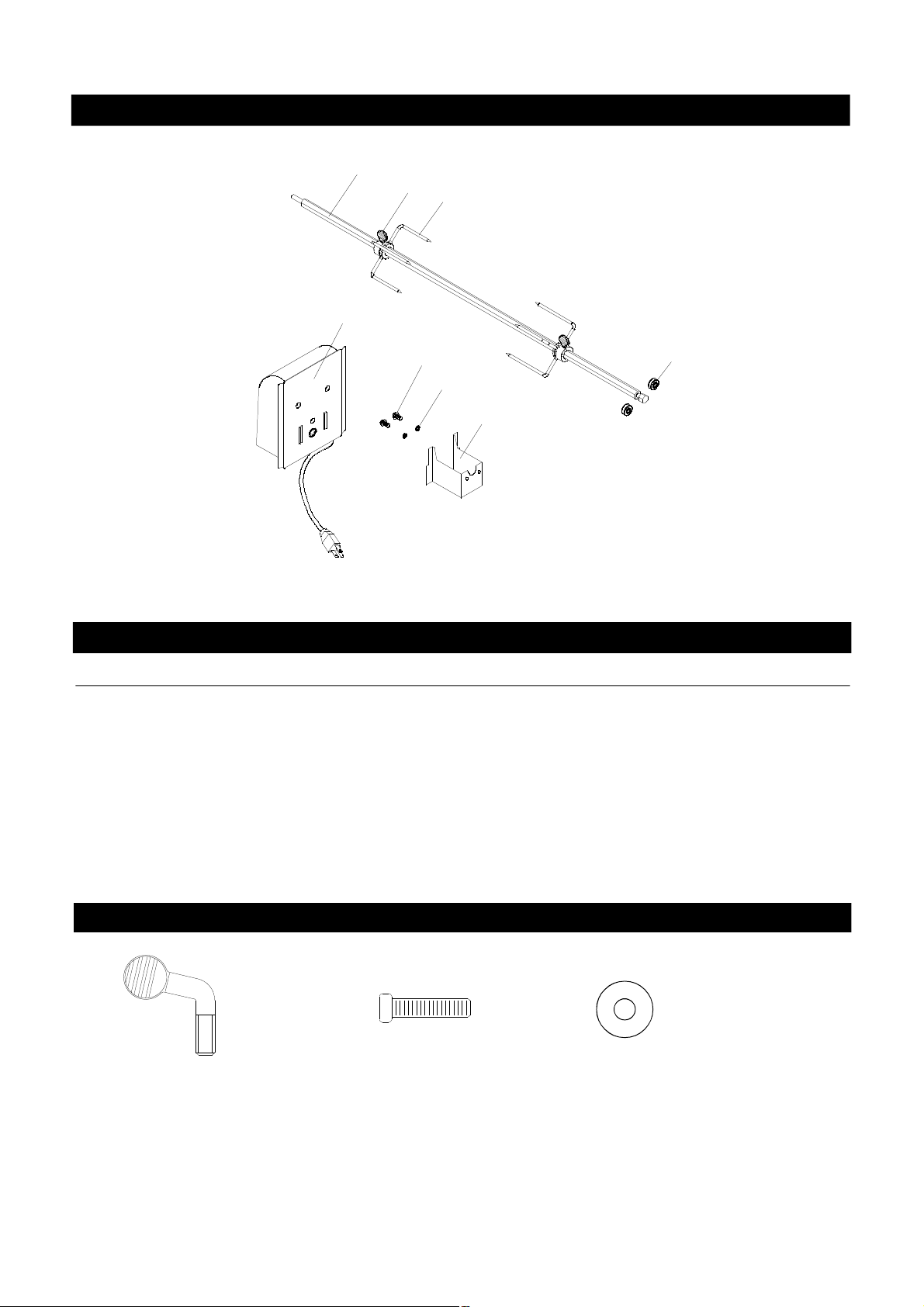
Rotisserie Assembly Parts Diagram for B3816ALP/NG & B3816BLP/NG
3
2
4
6
KEY
1.
2.
3.
4.
5.
6.
7.
8.
7
8
5
1
Rotisserie Assembly Parts List
PART#DESCRIPTION QTY
1.
2.
3.
4.
5.
6.
7.
8.
9.
Rot. Roller
Rot. Thumbscrew 1/4"x1/2"
Rot. Spit
Rot. Holding Fork
Rot. Motor Bracket
Rot. Motor/AC
Rot. Screw 3/16"x1/2"UNC
Rot. Washer 3/16"
P05508181A
S195G04081
P05508256A
P05508077A
P03308002A
P07101031B
S112G03084
S411G03064
2
2
1
2
1
1
2
2
Hardware for Rotisserie
Rot. Thumbscrew
1/4"x1/2"
Qty. 2
Part # S195G04081
Grill Information Center: If you have questions about assembly or grill operation, or if there are damaged
Grill Information Center: If you have questions about assembly or grill operation, or if there are damaged or missing
or missing parts when you unpack this unit from the shipping box, call us 8:00 am - 8 pm CST, Monday
parts when you unpack this unit from the shipping box, Call 1-800-474-5587 M-F 8AM-4:30 PM PST
Rot. Screw 3/16"x1/2"
UNC
Qty. 2
Part # S112G03084
through Friday at: 1-888-317-7642
14
Rot. Washer 3/16"
Qty. 2
Part # S411G03064
 Loading...