

GRAND EFFECTS Model 100 Owner's Manual

For your safety:
If you smell gas:
1. Shut off gas to the appliance
2. Extinguish any open flame
near unit.
3. If odor continues, immediately
call your gas supplier
For your safety:
Do not store or use any gasoline or
other flammable vapors and / or
liquids in the vicinity of this or any
other appliance.
GRAND EFFECTS
360 Fire-Water Bowls and
Fire-Water Inserts
Model 100
OWNER’S MANUAL /
OPERATING AND MAINTENANCE INSTRUCTIONS
This manual should remain with the homeowner or parties responsible for operation.
(Rev A)

2
Table of Contents
Gas and Electrical Requirements Page 3
Installation of Fire Water Insert Page 3
Burner Setup and Adjustment Page 8
Maintenance Page 9
Operation Page 10
Troubleshooting Page 11
Control Panel Wiring Diagram Page 12
Burner Assembly Wiring Diagram Page 13

3
1.0 Gas and Electrical requirements:
1.1 Input Voltage: 120 Vac / 60 Hz to Grand Effects Control Panel
1.2 Gas type: Natural Gas Propane
1.3 Gas Pressure: Nominal: 7” wc 11”wc
1.4 Gas flow: 1 Burner System: 60,000-80,000 Btu/Hr
1.5 Water flow: 25-50 gpm (Flow will vary depending on bowl size and flow
preference)
Note: Check with your gas supplier to verify gas flows and pressures available at the location
of your installation. In many cases utility companies will install larger meters at no charge to
accommodate larger flows.
2.0 Installation for 360 Water Fire Bowl/ Water Fire Bowl Insert
Warning: This unit is for outdoor use only
Recommended CSA/AGA Clearances: Sides 4ft/Top 6ft
2.1 Do not install near any combustibles such as wood structures, fuels, clothing, fabrics
or dry vegetation.
2.2 Install Burner Assy well out of the way of pedestrian traffic.
2.3 Installation shall be performed by a licensed contractor. All aspects of installation
must conform to local or National codes, or in the absence of codes, with National Fuel
Gas Code ANZI Z223.1.
2.4 The Control Panel and approved manual gas valve shall be located where they can be
easily accessible so that the gas can be shut off quickly in case of an emergency.
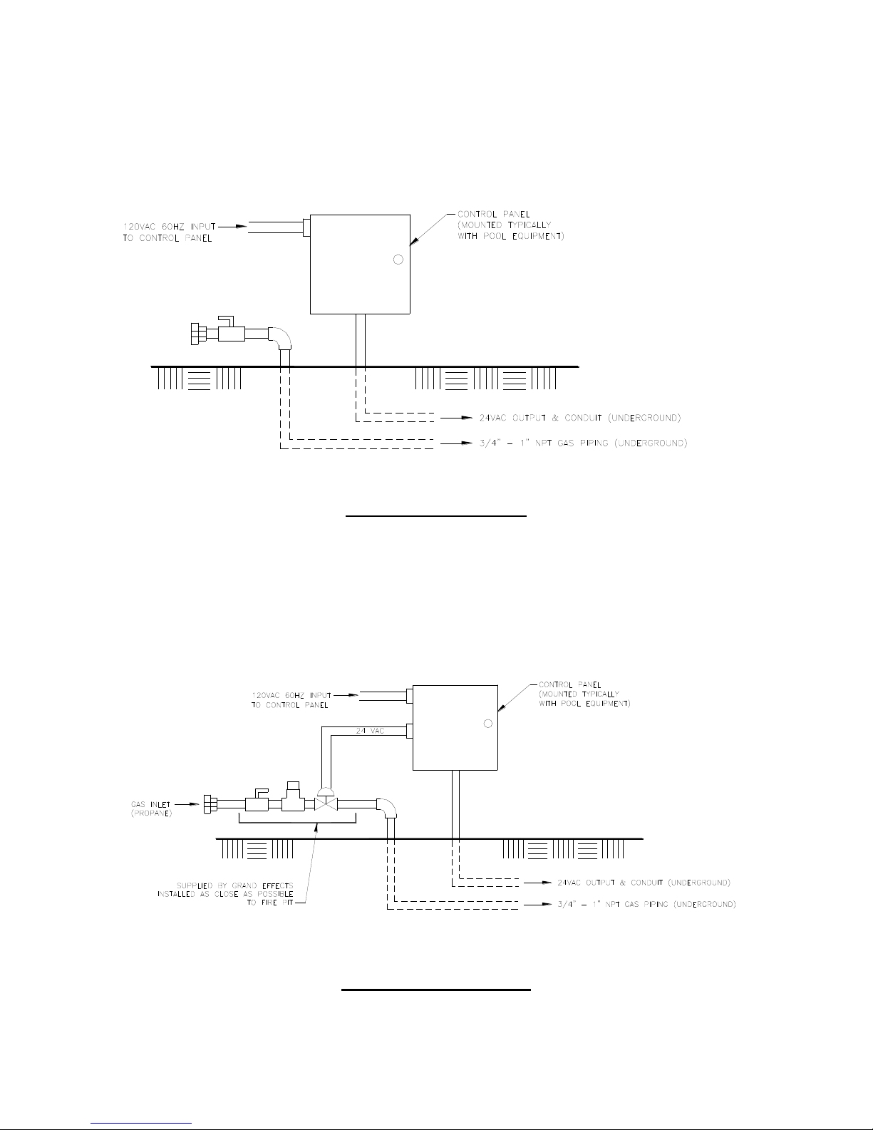
2.5 Install the Control Panel and gas piping as shown in Fig. 1(Natural Gas) or
Fig. 2 (Propane Gas) or Fig. 3 (Commercial Installation).
2.6 Note that piping is different for propane than natural gas as shown in Fig. 1 and Fig. 2
2.7 Low voltage 14 or 16ga wiring (24Vac) shall be installed underground between the
Control Panel and the Burner Assembly. Wire per Grand Effects Wiring Diagram. 120v
source into Control Typically, the pool controller is the device that turns the unit on/off.
If a pool controller is not available, Grand Effects can provide a hand held remote
system or an electrician can wire a decorative switch for on/off control up stream of the
Grand Effects Control Panel. Panel can come from any 120v source, including pool
controller or home system.
2.75 Control Panel should be installed at higher elevation than water bowl.
2.8 Maintain good piping practice by keeping pipe length and elbows to a minimum to
eliminate unnecessary pressure drops. (Do not use any corrugated flexible gas line).
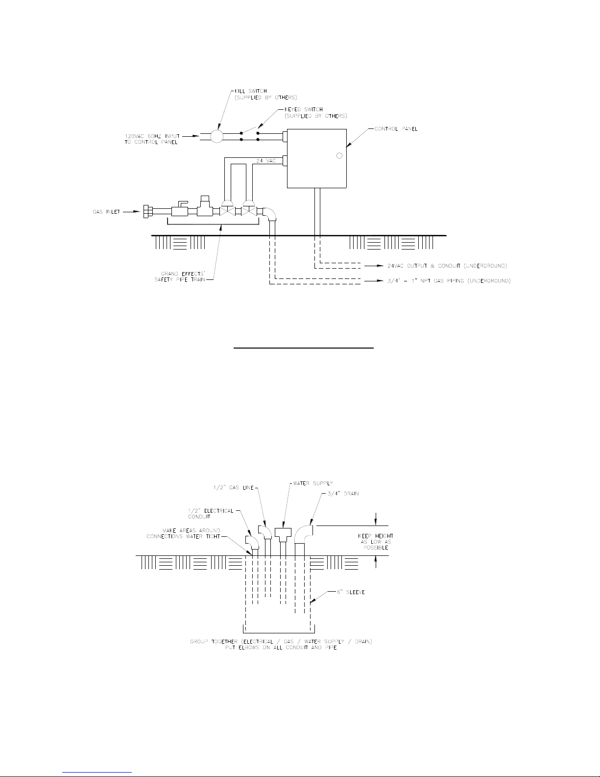
2.9 On commercial installations, it is recommended to install a keyed switch and kill switch
located in close proximity and in visible sight of feature or features. The keyed and kill
switches are supplied by others.
2.91 Gas/electrical and drain connections must be located to fit in a 6” sleeve. Make area
around connections water tight as shown in Fig. 4. Elbows need to be installed on
gas/electrical and drain for hoses to be positioned properly as shown in Fig. 4
4
Note: Control Panel should be installed at higher elevation
than Fire-Water Feature
Set up for Natural Gas
Fig. 1
Set up for Propane Gas
Fig. 2
5
(Commercial Installation)
Fig. 3
Fig. 4
 Loading...