

GRAND EFFECTS 100A Installation Manual
GRAND EFFECTS
For your safety:
If you smell gas:
1. Shut off gas to the appliance
2. Extinguish any open flame
near unit.
3. If odor continues, immediately
call your gas supplier
For your safety:
Do not store or use any gasoline or
other flammable vapors and / or
liquids in the vicinity of this or any
other appliance.
(Automated) Model 100A
OPERATING AND MAINTENANCE INSTRUCTIONS
This manual should remain with the homeowner or parties responsible for operation.
(RevH)
Fire Pit Inserts
INSTALLATION GUIDE

2
Table of Contents
Gas and Electrical Requirements Page 3
Installation of Fire Pit Insert Page 6
Burner Setup and Adjustment Page 8
Maintenance Page 9
Operation Page 9
Spare Parts Page 10
Troubleshooting Guide Page 11
Control Panel Wiring Diagram Page 12
Burner Assembly Wiring Diagram Page 13

3
1.0 Gas and Electrical requirements:
1.1 Input Voltage: 120 Vac / 60 Hz to Grand Effects Control Panel
1.2 Gas type: Natural Gas Propane
1.3 Gas Pressure: Nominal: 7” wc 11”wc
1.4 Gas flow: 1 Burner System: 80,000 Btu/hr
Note: Check with your gas supplier to verify gas flows and pressures available at the location
of your installation. In many cases utility companies will install larger meters at no charge to
accommodate larger flows.
2.0 Installation for Fire Pit Insert
Warning: This unit is for outdoor use only
Recommended CSA/AGA Clearances: Sides 4 ft/Top 6ft
unit is for outdoor use only
2.1 Do not install near any combustibles such as wood structures, fuels, clothing, fabrics
or dry vegetation.
2.2 Install Burner Assy well out of the way of pedestrian traffic.
2.4 Installation shall be performed by a licensed contractor. All aspects of installation
must conform to local or National codes, or in the absence of codes, with National Fuel
Gas Code ANZI Z223.1.
2.5 The Control Panel and approved manual gas valve shall be located where they can be
easily accessible so that the gas can be shut off quickly in case of an emergency.
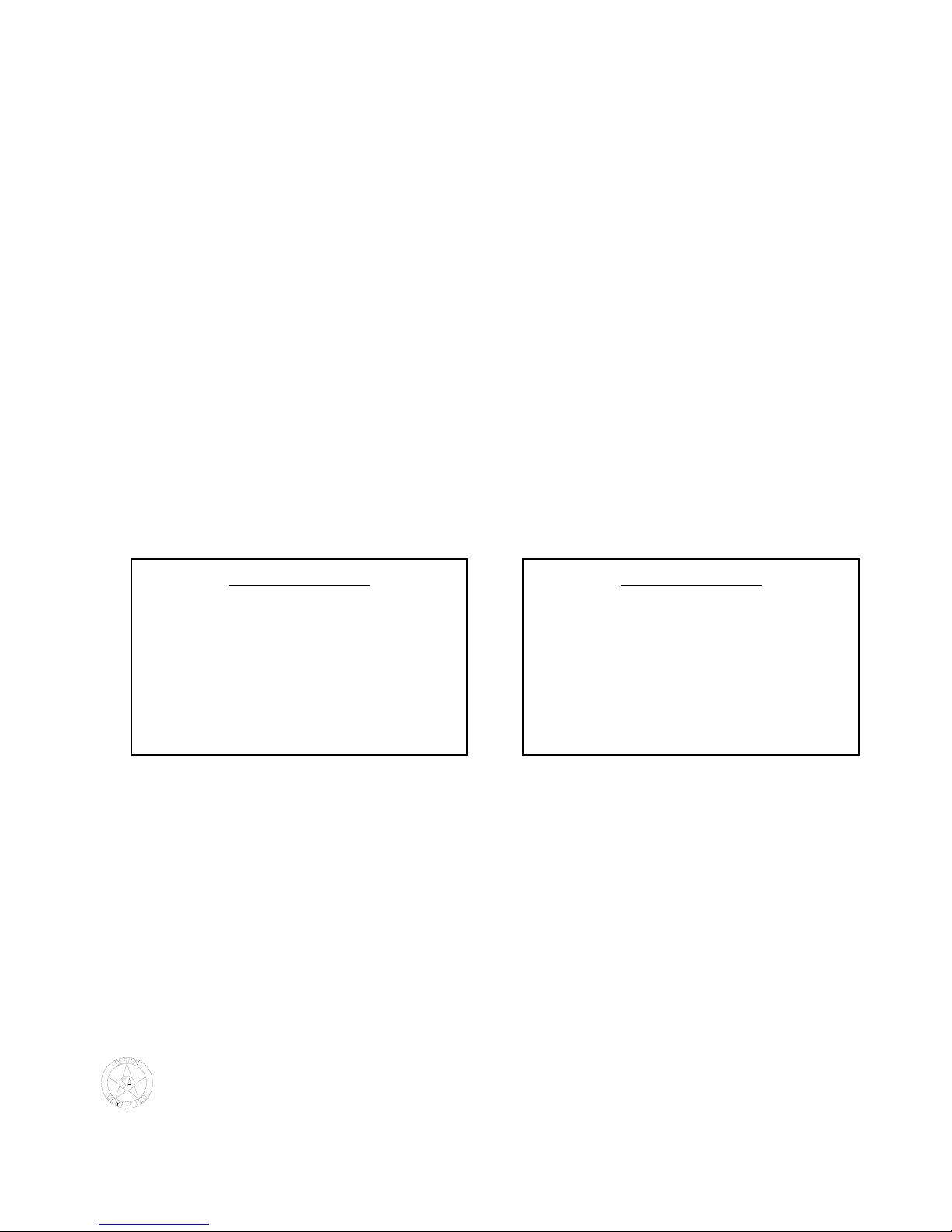
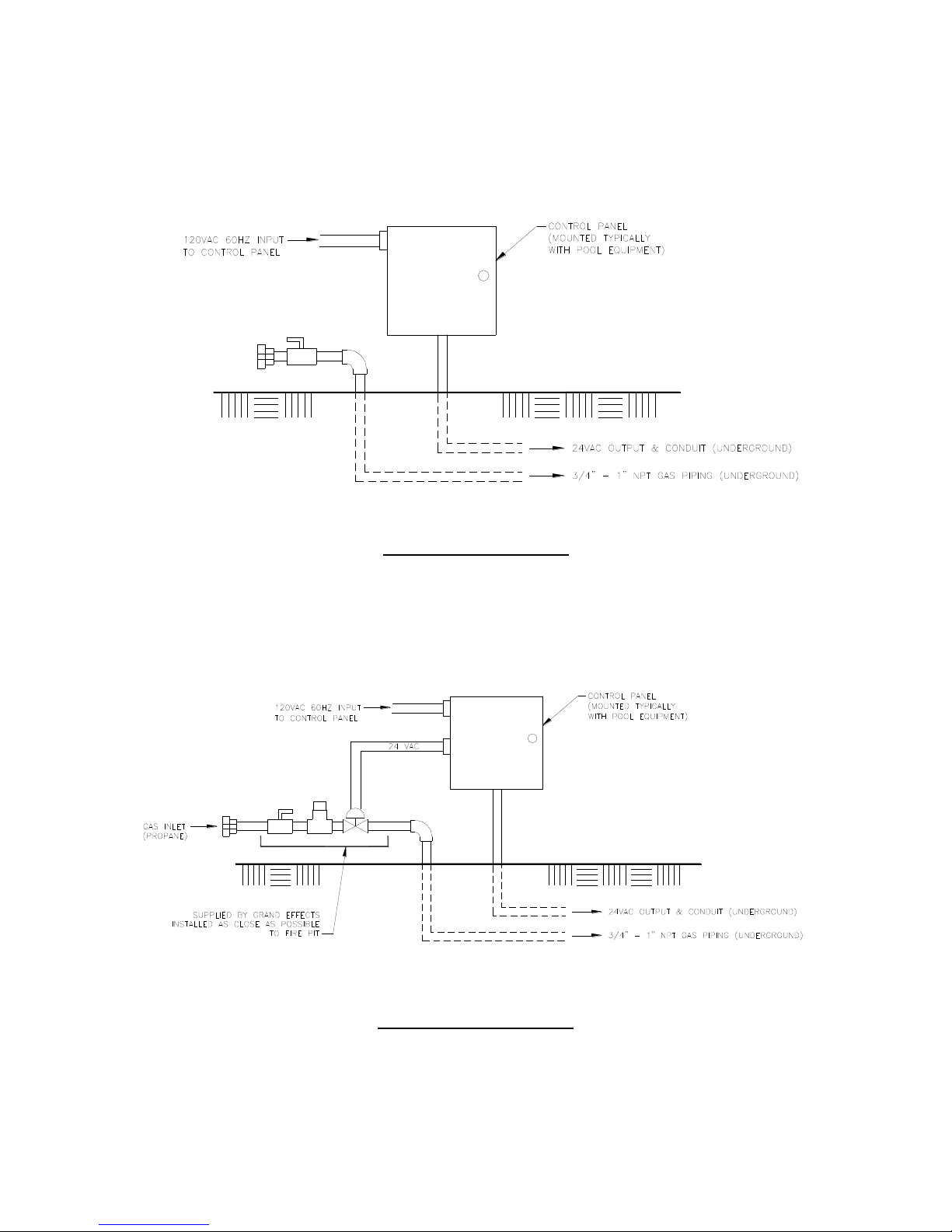
2.6 Install the Control Panel and gas piping as shown in Fig. 1(Natural Gas) or
Fig. 2 (Propane Gas) or Fig. 3 (Commercial Installation). Gas lines must be clean and
free from any dirt, debris or contamination
2.1 A gas pipe elbow must be installed on gas line for proper installation of gas hose.
(See Fig. 4) Do not kink or make tight radius bend on gas hose.
2.65 Note that piping is different for propane than natural gas as shown in Fig. 1 and Fig. 2
2.7 Low voltage 14 or 16ga wiring (24Vac) shall be installed underground between the
Control Panel and the Burner Assembly. Wire per Grand Effects Wiring Diagram. 120v
source into Control Panel can come from any 120v source, including pool controller or
home system. Typically, the pool controller is the device that turns the unit on/off. If a
pool controller is not available, Grand Effects can provide a hand held remote system
or an electrician can wire a decorative switch for on/off control upstream of the Grand
Effects Control Panel.
2.8 Providing good drainage is critical as shown in Fig. 4
2.9 Venting (air gap at bottom of fire pit walls) is required as shown in Fig. 4 and Fig. 5.
2.8 Maintain good piping practice by keeping pipe length and elbows to a minimum to
eliminate unnecessary pressure drops. (Do not use any corrugated flexible gas line).
2.9 Adjust the height of the Support Plate as shown in Fig. 3 & 4. Cut off excessive length
of bolts.
2.95 On commercial installations, it is recommended to install a keyed switch and kill switch
located in close proximity and in visible sight of feature or features. The keyed and kill
switches are supplied by others.
2.96 Using fire brick to line the inside of the fire pit is not recommended. Fire brick will retain
heat and may result in over heating of the electronics.
4
IMPORTANT!!
Note: 18” Minimum Depth Requirement of Fire Pit (as shown in Fig. 4 and Fig. 5)
Venting is required for cooling Burner Assembly (as shown in Fig. 4 and Fig. 5)
Set up for Natural Gas
Fig. 1
Set up for Propane Gas
Fig. 2

5
Fig. 3 (Commercial Installation)
Important: Do not kink or make sharp radius on metal gas hose. Do not come
straight up with gas hose. As shown below, a 90 gas pipe elbow must be installed on
gas line for proper installation of gas hose. If not installed with elbow as shown
below, product warranty will be void.
Fig. 4 (Natural Gas- Residential Installation)
 Loading...