

Grand Canyon Gas Logs WBECS Owner's Operation And Installation Manual

Weather Beater Electronic
CALIFORNIA PROPOSITION 65
(For more information, go to: www.p65warnings.ca.gov)
Control System
Model: WBECS
Owner's Operation and
Installation Manual
WARNING: FOR OUTDOOR USE ONLY!
WARNING: Improper installation, adjustment, alteration, service or maintenance can cause
injury or property damage. Read the installation, operating and maintenance instructions
thoroughly before installing or servicing this equipment.
WARNING: Do not store or use gasoline or other ammable vapors and liquids in the vicinity
of this or any other appliance.
WARNING: A propane cylinder not connected for use shall not be stored in the vicinity of
this or any other appliance.
WARNING: For use with Natural or Propane gas only. NO SOLID FUELS TO BE USED WITH
THIS SYSTEM.
If you smell gas:
1. Shut off gas to appliance.
2. Extinguish any open ame.
3. If odor continues, keep away from appliance and im-
mediately call your gas supplier or re department.
This product can expose you to Chromium, which is known to the state of
California to cause cancer and birth defects or other reproductive harm.
WEBCS-1 09/18
FOR YOUR SAFETY
WARNING
1

The Weather Beater Electronic Control System utilizes CSA certied components
to be added to an outdoor product.
Installation must conform with local codes or, in the absence of local codes, with the National
Fuel Gas Code, ANSI Z223.1 / NFPA, or International Fuel Gas Code.
The appliance, when installed, must be electrically grounded in accordance with local codes
or, in the absence of local codes, with the National Electric Code, ANSI/NFPA 70, if applicable.
INSTALLER: Leave this manual with the appliance.
CONSUMER: Retain the manual for future reference.
TABLE OF CONTENTS
System Overview............................................................... 2
Electronics ......................................................................... 2
Gas Valve and Pilot Components ...................................... 2
Gas Requirements............................................................. 3
Ignition Control Specications and Wiring Diagram .......... 3
Product Dimensions .......................................................... 5
Installation ......................................................................... 5
Gas Connection ................................................................. 6
Pilot Assembly Connections
Proper Venting ................................................................... 7
Acceptable Media .............................................................. 7
Operation ........................................................................... 7
Maintenance ...................................................................... 8
FAQ and Helpful Tips for proper operation ........................ 8
Troubleshooting ................................................................. 9
Parts List & Accessories ...................................................11
.............................................. 6
SYSTEM OVERVIEW
• Components are CSA Certied.
• 12 vac system to comply to NEC 2014 Article 680 require-
ments.
• -20° to 175° temperature range.
• Durable connections designed to resist outdoor conditions.
• 265,000 BTU’s at 1" pressure drop.
ELECTRONICS
• Certied ANSI Z21.20-2014
• 12 VAC for installation within 5 feet of water.
• Potted control module to protect against moisture and
damage.
• Hot Surface Ignition (HSI), provides stable burner ignition
in harsh conditions.
GAS VALVE AND PILOT COMPONENTS
• All connectors are water resistant.
• Certied CSA 229521-1656058.
• Coils are encapsulated to protect against moisture.
• Pilot has robust ame pattern, wind resistant.
• Pilot injectors are stainless steel.
• TC Flame-sense system.
• Hot Surface Ignitor (HSI).
• LED diagnostics.
• Electronics are ANSI Z21.20-2014 certied.
• I-Flame app is available as an option.
• Thermocouple Flame Sense, fast responding and resistant
to wind, moisture and corrosion.
• LED diagnostics for eld service and troubleshooting.
• Thermocouple is nickel plated for durability.
• Hot Surface Ignitor (HSI) with protective cage.
• Hot Surface Ignitor (HSI) connection is waterproof.
• The Power Wire connector is waterproof.
2
WEBCS-1 09/18
GAS REQUIREMENTS
FUEL TYPE
Prior to making gas connections, ensure appliance being
installed is compatible with the available gas type. Check
the label on the appliance to conrm appliance gas type
requirement.
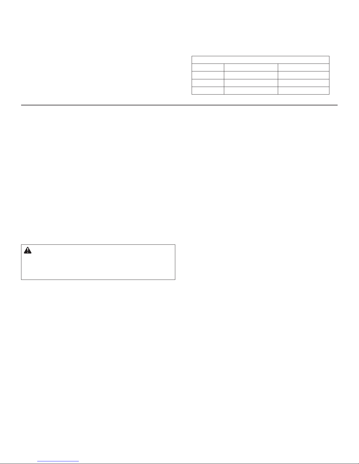
Proper input gas pressures are required for optimum appliance performance.
Pressure Natural Gas Propane Gas
Minimum 3.5" W.C. 1/8 PSI 8" W.C. 1/3 PSI
Nominal 7" W.C. 1/4 PSI 11" W.C. 1/3 PSI
Maximum 14" W.C. 1/2 PSI 14" W.C. 1/2 PSI
GAS PRESSURE
Gas Pressure Requirements
IGNITION CONTROL SPECIFICATIONS AND WIRING DIAGRAM
RECOMMENDED WIRE SIZE
No less than 16 gauge wire for all installations
Note: There are numerous electrical devices that can be used to turn the re feature on and off. Devices such as wall
switches and remote control devices that are used should be UL listed and approved devices for turning high voltage (110
v electrical power) on and off.
WBECS IGNITION CONTROL TIMING
Pre-Purge 3.25 seconds
HSI Warm Up 5 seconds
Trial for Ignition 20 seconds
Flame Failure Response 10 seconds Max
Inter-Purge 5 seconds
Flame Loss Recycles 15 seconds
Flame Loss Recycles Delay None
ELECTRICAL REQUIREMENTS
WARNING: The Weather Beater Electronic Control
System operates on 12 Volts AC power.
DO NOT attempt to power using 110 Volts AC Power!
DAMAGE WILL RESULT!
Acceptable Input Voltages to Supplied 12 Volt AC Transformer
110 / 120 Volt AC
Read label on supplied transformer for
proper connection information.
Recommended Wire Size
16 gauge wire for all installations (30 feet maximum length)
ELECTRICAL CONNECTIONS
The WBECS is supplied with a 12 volt all weather sealed
transformer of minimum 60 watts. If another transformer is
used it must meet be a Class ll 12 VAC, 5 amp, 60 watt or
larger for the unit to operate properly. A minimum 16 gauge
WIRING OF MULTIPLE WBECS
The WBECS has a red and a black wire protruding from
it. These are the power wires. When multiple WBECS are
connected, the polarity between them must be the same. To
achieve this, all of the red wires must be connected to the
same wire from the transformer and all of the black wires
connected to the other wire from the transformer as shown
in this illustration.
IT IS NECESSARY TO USE A HIGHER OUTPUT
TRANSFORMER WHEN CONNECTING TWO UNITS.
wire must be used for installations up to 30 feet in total line
length, and 12 gauge for installs up to 100 feet. It is highly
recommended to use dielectric grease or silicon to ll any and
all wire nuts used in installation of the WBECS.
WEBCS-1 09/18
3
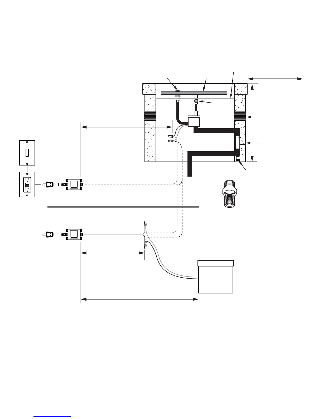
IGNITION CONTROL SPECIFICATIONS AND WIRING DIAGRAM
Appliance Manufacturer’s
Top, Sides and Bottom
Clearances to
Combustibles must
be maintained in
accordance with the
120 Volt AC Options
(Most common Shown)
Wall
Switch
Transformer
For Single Unit Installation
GFCI
Outlet
12 VAC
5 Amp Minimum
30' Maximum Wire Length
16 AWG
Pilot Burner Assembly
Red
Black
Burner
Ignition
Control Box
Gas
Line
Burner Pan
Orifice
Sediment Trap
Air Mixer for Propane is
Recommended for
Propane burners.
See instructions included
with the burner or
appliance.
specifications and
local codes.
Minimum
18 sq inches of
Cross Ventilation
on Each Side
of Enclosure
Manual Gas Shutoff
(Key Valve)
For 2 Unit
Installation
10 Amp Minimum
Wiring Two Units
5' Maximum
Wire length from transformer to splice
point must be less than 5' using
16 gauge wire
30' Maximum
Wire length from transformer to splice point
must be less than 30' using 16 gauge wire
Red
Black
2nd Unit
Red
Black
4
WEBCS-1 09/18
 Loading...