

Page 1

Model No.: MX0404-HE1
Operating Instructions
Thanks for purchasing our product.
Please be sure to read this instruction manual
Carefully before using our product.
Page 2

Introduction
Grandbeing’s MX0404-HE1 is a 4-by-4 DVI/HDMI true matrix. It allows any
source (Blue-Ray player, HD DVD player , satellite receiver, game system, etc.)
to be shown on the any of the four displays simultaneously, no matter the
source is HDCP or not. Extra infrared receiver extension, IR emitter, RS232
and Ethernet port are supplied for remote control.
MX0404-HE1 has the ability of equalization and am plification to ensure HDMI
signal's transmission through long cable without quality loss.
MX0404-HE1 offers solutions for digital entertainment center, HDTV retail and
show site, HDTV, STB, DVD and projector factory, noise, space and security
concerns, data center control, information distribution, conference room
presentation, school and corporate training environments.
Page 3

Contents
HDMI Matrix ..................................................................................................... 1
Product Overview ............................................................................................ 1
Features ........................................................................................................... 1
Package Contents............................................................................................ 3
Panel Descriptions ........................................................................................... 3
Front Panel ...................................................................................................... 3
Back Panel ....................................................................................................... 4
Installation ........................................................................................................ 4
Operation ......................................................................................................... 5
Specifications ................................................................................................. 16
Typical Application ......................................................................................... 17
Maintenance .................................................................................................. 18
Provided Service ............................................................................................ 18
Mail-In Service ............................................................................................... 18
Warranty ........................................................................................................ 19
Warranty Limits and Exclusions ..................................................................... 19
Page 4

Page 5

Page 1
HDMI Matrix (Router Type)
■ Product Overview (Model Number: MX0404-HE1)
■ Features
z Easy to use, install in seconds.
z Allows up to four HDMI audio/video devices to be independently switched
to four HDMI monitors, HDTV’s, or projectors.
z The four outputs could show the same or different source simultaneously
no matter the source is HDCP or not.
z The four outputs are all include one HDMI-A output port and one HDBT
output port. They can output simultaneously.
z Support high definition resolutions 1080p, 1080i, 720p and other standar d
video formats.
z Each port supports HDMI or DVI inputs.
z With extra infrared receiver extension.
z Five switching modes: panel buttons, local IR, IR call back from remote
rooms, RS232 and Ethernet.
z IR system could control the sources from the sinks or control the sinks
from sources.
z HDCP compliant.
z HDMI 1.3 version.
z 3D support.
Page 6
Page 2
" Notice
Grandbeing Inc. reserves the right to make changes in the hardware,
packaging and any accompanying documentation without prior written notice.
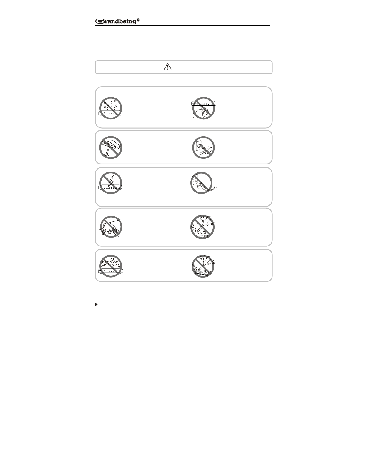
Warning
To reduce the risk of fire, electric shock or product damage:
1. Do not expose this apparatus
to rain, moisture, dripping or
splashing and that no objects
filled with liquids, such as vases,
shall be placed on the apparatus.
6. Clean this apparatus
only with dry cloth.
2. Do not install or place this unit
in a bookcase, built-in cabi net or
in another confined space.
Ensure the unit is well ventilated.
3. To prevent risk of electric
shock or fire hazard due to
overheating, do not obstruct
the unit’s ventilation openings
with newspapers, tablecloths,
curtains, and similar items.
4. Do not install near any heat
sources such as radiators, heat
registers, stoves, or other
apparatus (including amplifiers)
that produce heat.
5. Do not place sources of naked
flames, such as lighted candles,
on the unit.
7. Unplug this apparatus
during lightning storms or
when unused for long
periods of time.
8. Protect the power cord
from being walked on or
pinched particularly at
plug
s.
9. Only use attachments /
accessories specified by
the manufacturer.
10. Refer all servicing to
qualified service
personnel.
Page 7
Page 3
■ Package Contents
① Main unit. P/N_MX0404-HE1.
② 12V/DC Power Supply. P/N_VDC01205.
③ 1x Remote... (Battery type: CR2025 3V).
④ 1x IR extension cable (38 KHz IR receiver cable, connect to IR Ext
sockets of MX0404-HE1).
⑤ 4x IR emitter cable (connect to IR emitter sockets of MX0404-HE1).
⑥ 4x IR receiver cable (from 30 KHz to 56 KHz IR receiver cable, connect to
IR receiver sockets of MX0404-HE1).
⑦ Operating Instructions. P/N_INS MX0404-HE1.
NOTE: PART NUMBER (Abbreviation as P/N).
■
Panel Descriptions
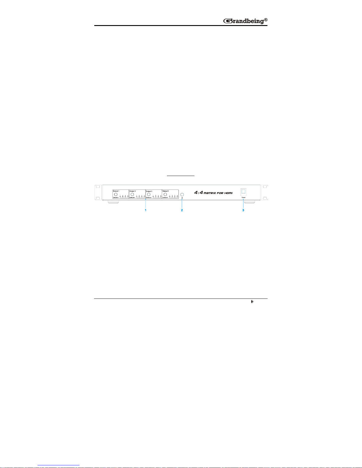
Front Panel
① Output selection and indicator of input for output port 1 to 4.
② IR window.
③ Power switch.
Page 8

Page 4
Back Panel
① RS232 port.
② LAN port.
③ DIP switch for EDID setting.
④ Power input.
⑤ IR extension.
⑥ Output 1 and 2 with HDMI and HDBT.
⑦ Input ports 1 to 4.
⑧ Output 3 and 4 with HDMI and HDBT.
⑨ IR emitter sockets.
⑩ IR receiver sockets.
NOTE: RS232 port and LAN port are for matrix control. The LAN port is connected to
the computer via direct UTP and connected to the router via cross UTP.
■
Installation
① Connect the HDMI input sources ( such as HD-DVD, PS3, STB etc)
into MX0404-HE1.
② Connect the HDMI outputs (
such as HD-LCD, HD-DLP) into MX0404-
HE1.
③ Use the HDMI cable to connect local HDMI sink device ( near to the
matrix) to MX0404-HE1. Use UTP cable to connect remote HDMI sink
devices to MX0404-HE1.
④ Power on the input source you want to show.
Page 9
Page 5
⑤ Connect the power supply into MX0404-HE1 and turn on the display you
want to watch.
⑥ Use remote or push the button to choose input source. Extra infrared
receiver extension, IR emitter, RS232 port and Ethernet are supplied for
remote control.
■ Operation
1. Front panel control
The MX0404-HE1 front panel control for switching inputs to the various outputs.
There are four groups of LEDs for each output port. The LED lit on the position
means that the output port selects this input as its source.
Page 10
Page 6
2. Local IR remote control.
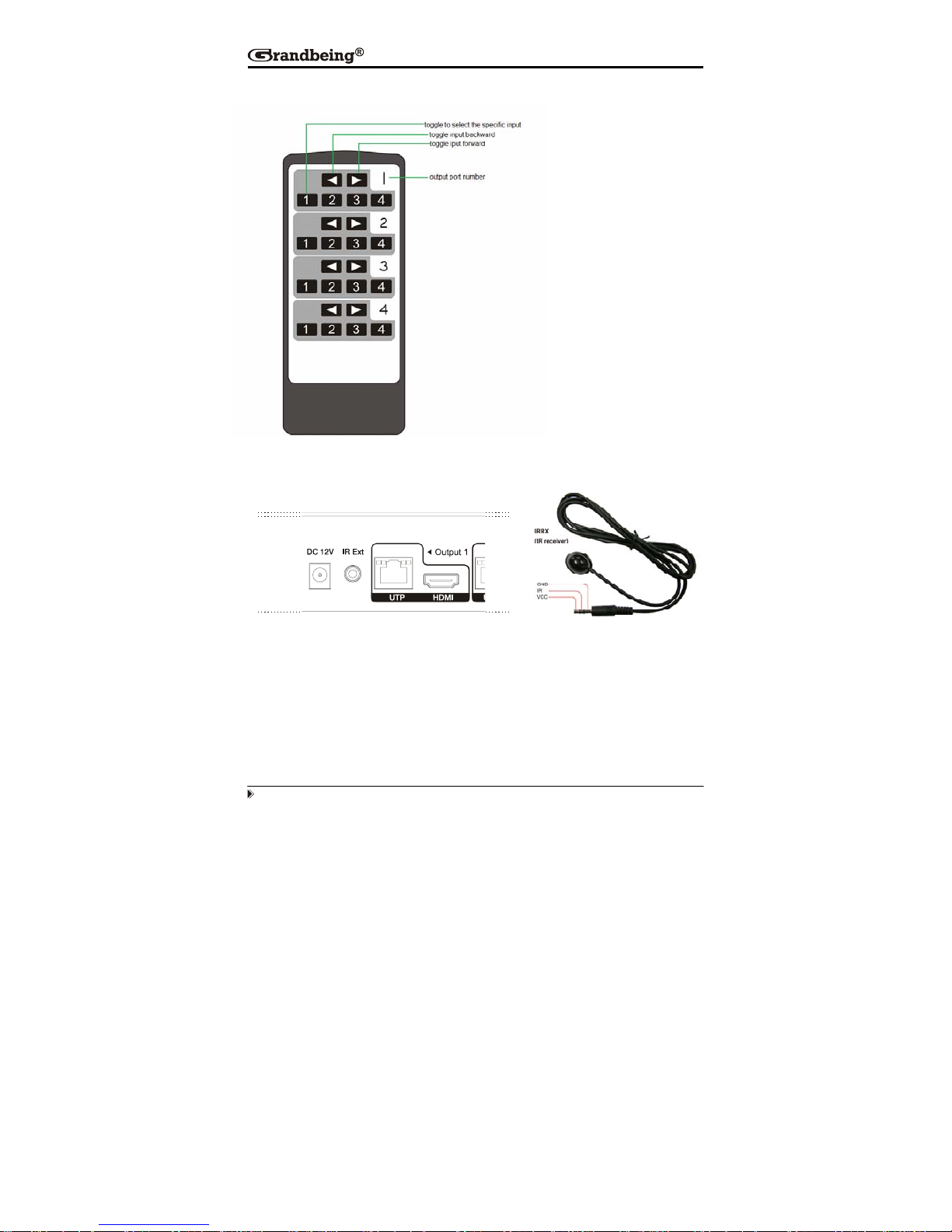
3. IR extender control
User can use the IR receiver cable to change the IR receiver position.
If controlling the MX0404-HE1 through the 1/8” (3.5 mm) input jack on the rear
panel, connect the IR cable directly to the matrix rear IR Ext socket.
User can control the
HDMI route of the matrix
by using the IR remote.
There are four group key
pads for four output port.
For each output port
source selection, there
are 4 number key and
two arrow key. Press
number key to select
specific input port. Left
arrow is to backward the
input port, and right arrow
to forward in
p
ut port.
Page 11
Page 7
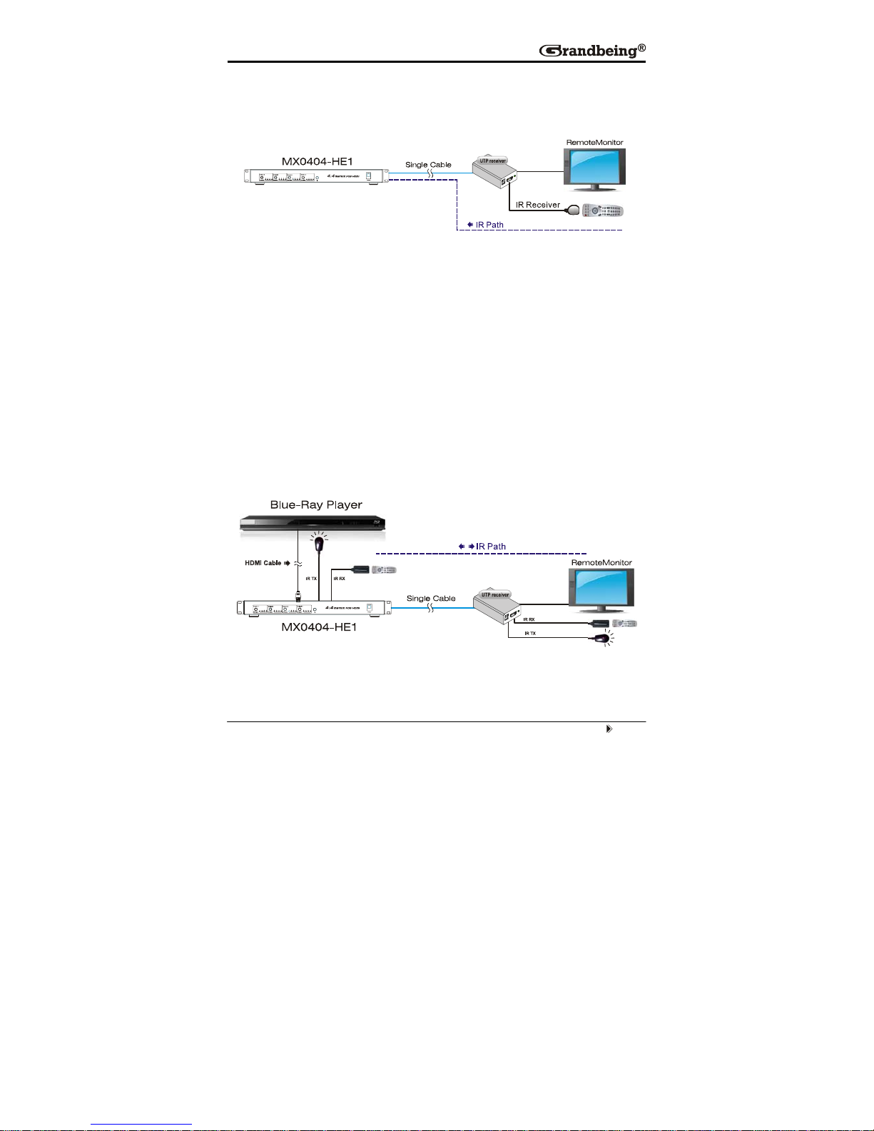
4. IR call back control the matrix
User can control the matrix via the IR call back system.
This function can be disabled or enabled.
Enable the function: press the output2 selection button and the output4
selection button at the same time for about 3 seconds. After all the output1
LEDs and the output2 LEDs flash once, the function is enabled.
Disable the function: press the output2 selection button and output4
selection button at the same time for about 3 seconds. After all the output1
LEDS and the output2 LEDS flash twice, the function is disabled.
5. IR system could control the sources from the sinks or control the sinks from
sources.
Page 12
Page 8
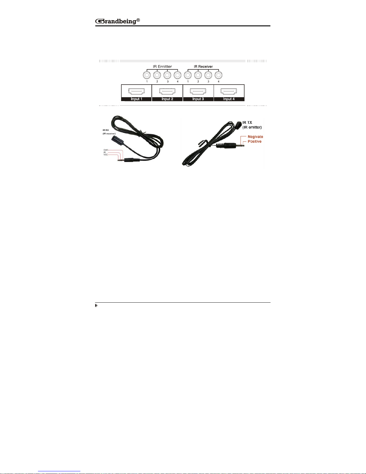
The matrix can not only extend the HDMI signal to HDMI receiver which is in
remote rooms, but also can pass the IR signal through the IR system to the
HDMI source or pass the IR signal from the HDMI source to the HDMI sink.
There are four IR emitter sockets for connecting IR TX cable. The IR TX signal
is reversed to HDMI signal. That is, when user is watching the STB signal
which is connected to input3, the IR signal will go to the IR_TX3 socket.
Because the each IR emitter socket is related to one HDMI input port. Be sure
that the IR TX cable connected to the IR emitter socket and stick the IR emitter
to the IR window of the HDMI source device which has been connect to the
related input port. For example, STB connected to input1, and then if user
wants to control the STB via the IR call back system, plug the IR TX jack to the
IR emitter socket source1. And, stick the IR emitter near to the IR window of
the STB.
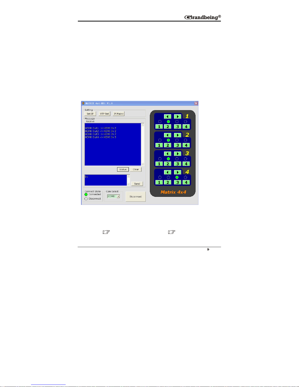
There are four IR receiver sockets for connecting IR RX cable. The IR TX
signal is forward to HDMI signal.
Press the output1 selection button and output4 selection button at the same
time for about 3 seconds. After all the output LEDS flash, the matrix go into the
Page 13
Page 9
IR TX matrix switch mode. The each IR receiver socket is related to one HDBT
output port. Be sure that the IR RX cable connected to the IR receiver socket
and stick the IR emitter to the IR window of the HDMI sink device which has
been connect to the related HDBT receiver. For example, HD LCD connected
to HDBT receiver which connected the HDBT output1 of the MX0404- HE1,
and then if user wants to control the HD LCD via the IR system, plug the IR RX
jack to the IR receiver socket 1. And, stick the IR emitter near to the IR window
of the HD LCD, go into IR TX matrix mode, press output1 button to select the
first IR channel.
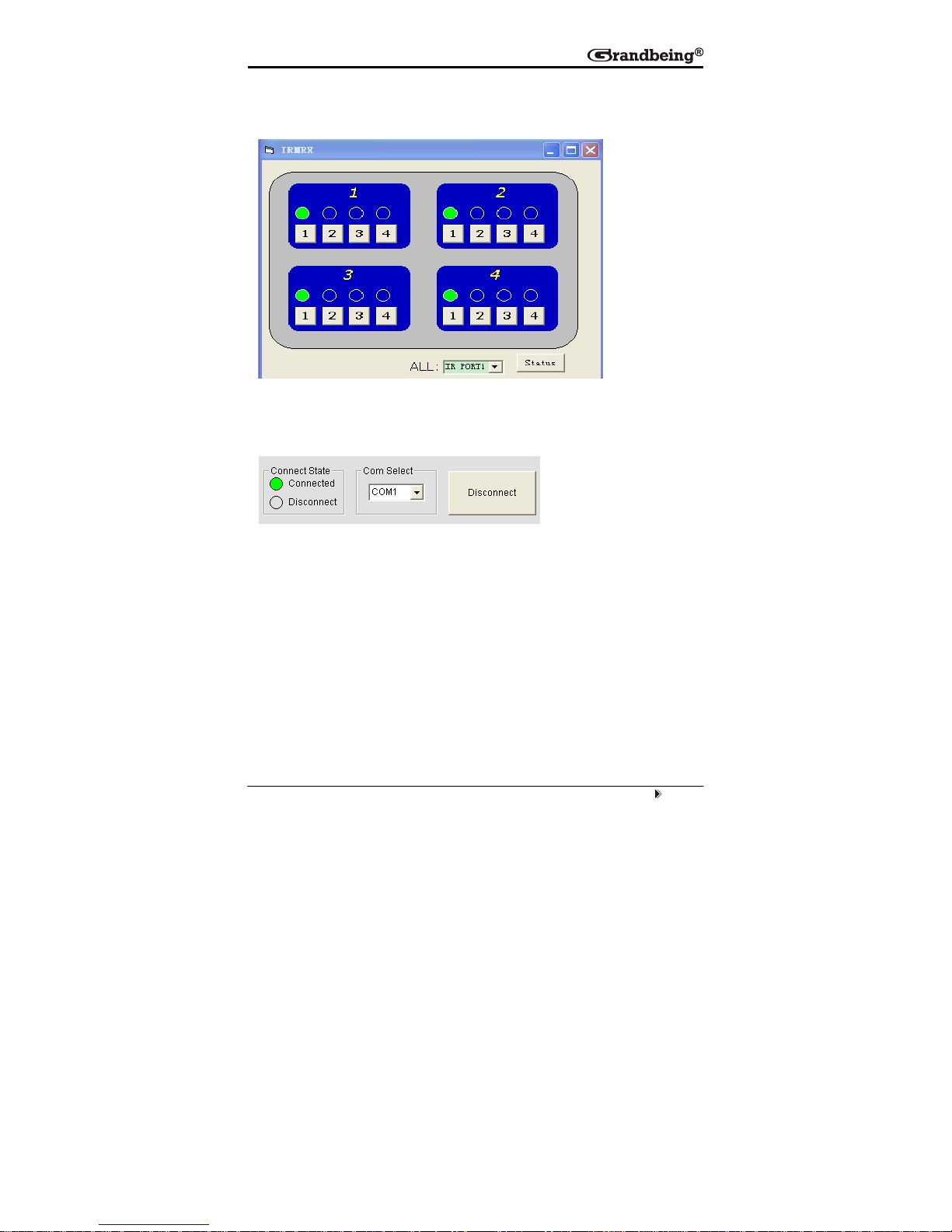
6. RS232 remote control.
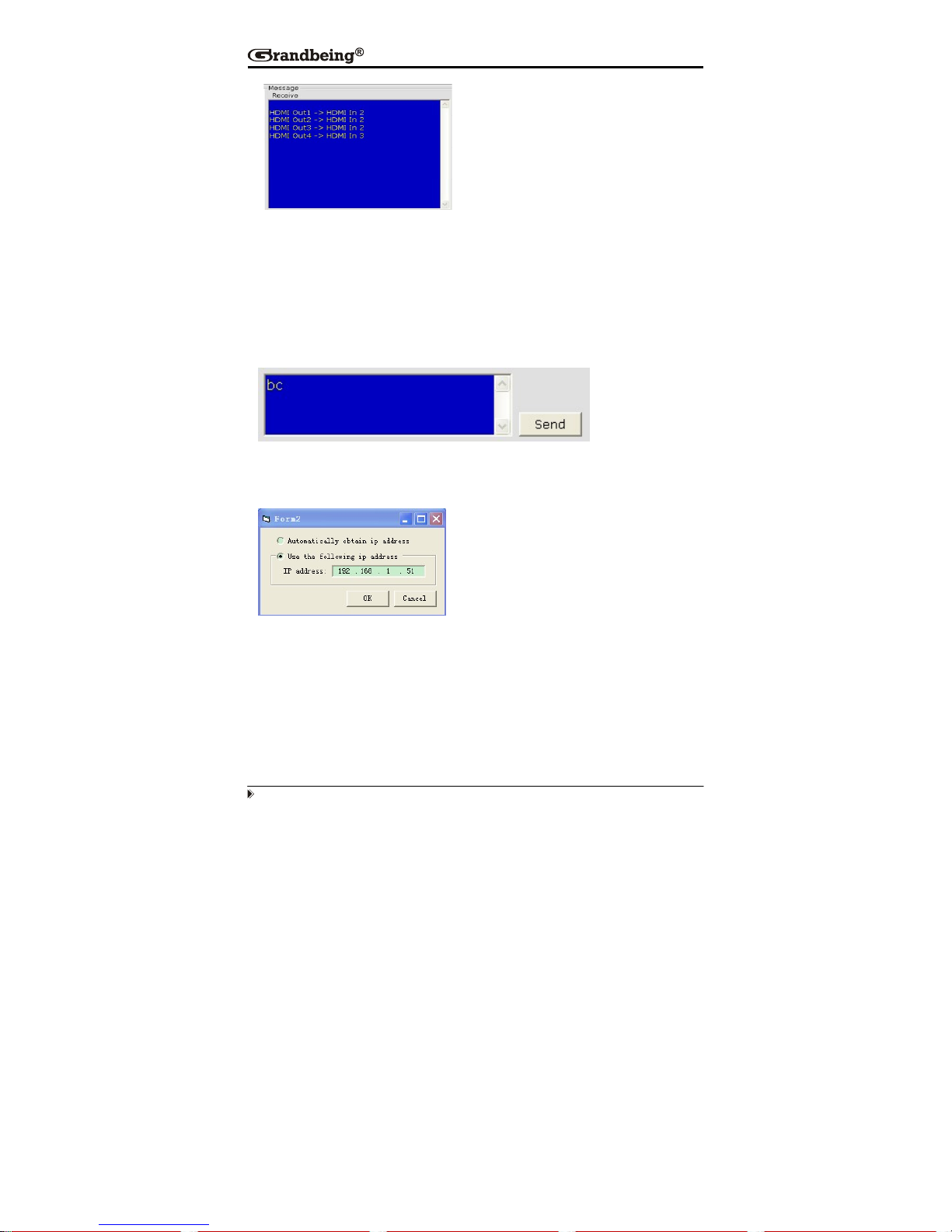
1. The Message Window
2.1 Receive Window
The “receive window” will show the message received from MX0404-HE1. When you click the
Control Buttons ( see step 4) or send Control Command ( see 2.3) to MX0404-HE1, it will
send out the message about “operation results” as below:
Page 14
Page 10
2.2 Status Button
Click this button to read the status of MX0404-HE1. The status is about w hich input is selected by
the output.
2.3 Send Window
Input the control command in this window. The control command use ASCII.
2.4 Set IP Button
Click this button to set IP address for nettle.
Page 15
Page 11
2.5 IR Matrix
In this menu, you can select the IR TX channel.
Click this button to write the codes onto the device.
3 The Com Status
3.1 connect state.
Connect state shows the com open or not. If it is open, the state is green. Otherwise, the state is
red.
3.2 com select.
Æ Select which com you will use.
Æ Connect button.
The word on this button will change when the connection state changes. If the word is
“Disconnect”, then click this button, the com will be closed. If the word is “Connect”, then click this
button, the com will be opened.
Page 16

Page 12
7. LAN Control.
Note: Use the direct UTP cable to connect with PC, or use cross cable to connect to the Ethernet
switcher
A. When NETCTL run on PC at the first time, it will create a file ‘NETCTL.TXT’. This file is
for device information’s backup. These information include MAC address of
MX0404-HE1, IP address, device name etc.
Double click NETCTL.exe to run NETCTL. It will search the device. If the device is a new one,
NETCTL will list it‘s IP address. If IP address appears, please click the button .
NETCTL will change the IP address to device name.
If you want to change the device name. Right-click the device name. A pull down menu will be
displayed. Click the item ‘Rename’ to rename it’s name.
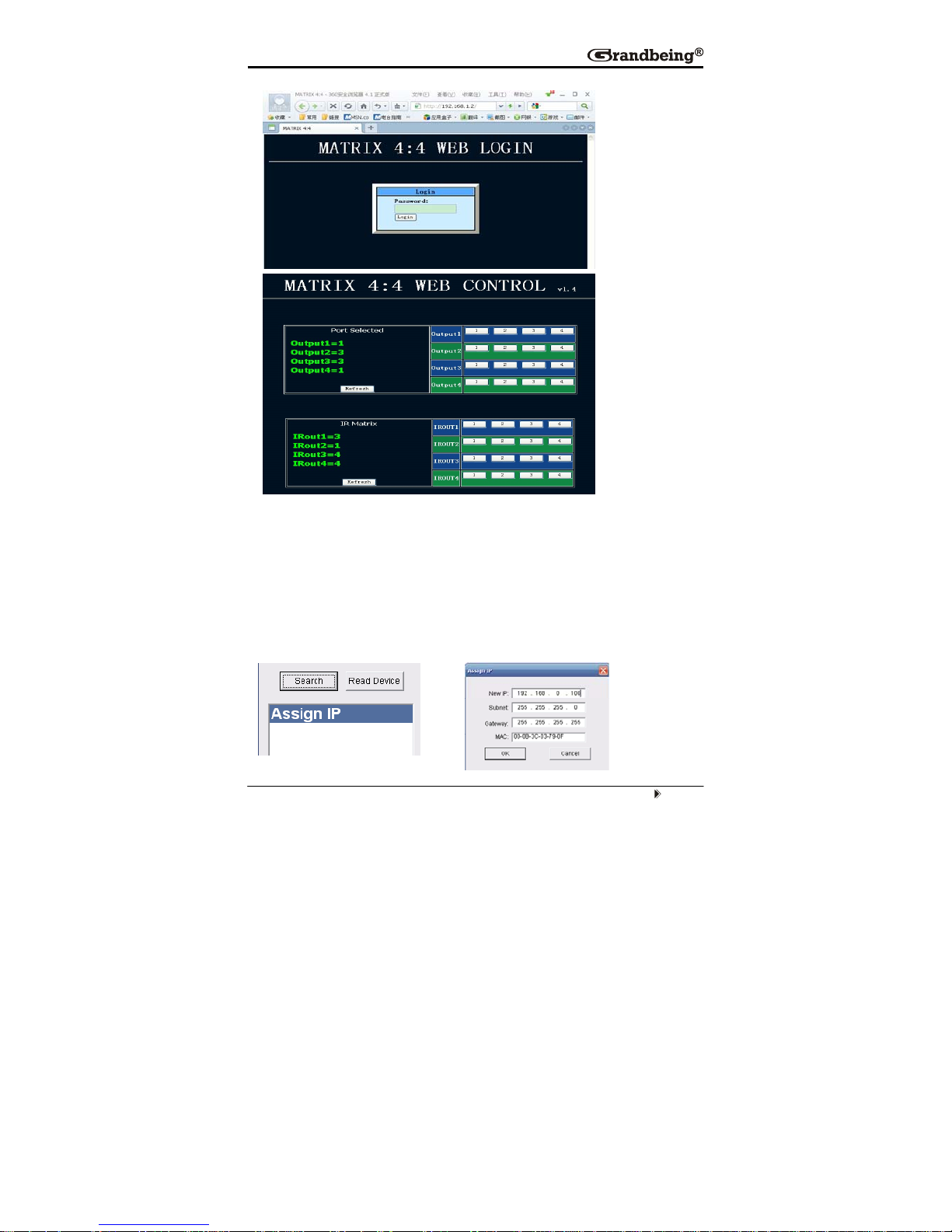
B. Double click the device name, or click right button and click the ‘open’. A web browser
will be shown. The default password is "0000000000", input the password and login. The
device controller page will be displayed.
Page 17
Page 13
The right area is for device controlling. Click these buttons to control the device. It is the same as
using the COM controller. The left area shows which input ports are being chosen by the output
ports.
C. When ‘Assign IP’ is displayed, it means that the device has not been assigned IP
automatically. Double click this item. Or click right button and click ‘Assign IP’ on the
pull down menu. You can assign the IP address in the Assign IP dialog.
Page 18

Page 14
Click OK after assign the new IP and to return to the previous dialog. Click
and . The device can be displayed correctly.
ATT EN TI ON :here assign IP is different from Set IP in COMCTL. Set IP in COMCTL is save the
IP address in flash, when the MX0404 power on, it will read the IP from flash and set it as st atic IP.
Assign IP function used when automatically obtain IP address failed. This assigned IP address is
not save in flash.
Switch for EDID setting. (Factory default setting: DIP in ‘010’ mode, EDID
are all 1080p and stereo.)
Position1 Position2 Position3 Function
0 0 0 copy HDMI Sink's edid to its current
selection of input port (note1)
0 0 1 1080P 3D stereo (note2)
0 1 0 1080p stereo (Using Embedded EDID)
(note3)
0 1 1 1080i stereo (Using Embedded EDID)
(note4)
1 0 0 1080p5.1(Using Embedded EDID) (note5)
1 0 1 1080p 7.1(Using Embedded EDID) (note6)
1 1 0 Reserved
1 1 1 Reserved
Note1: Copy the EDID data to the input port accordi ng to the matri x route
status. It will copy the EDID data from the output number port. For
example, when output-3 selects input-1, after pressing and holding the
Output 3 button for 3 seconds, it will copy the output-3’s EDID to input-1.
Note2: The matrix will use the embedded 108 0p-stereo 3D EDID when
the DIP switch is in this mode. The EDID will be 1080p 3D video and
stereo audio. The EDID data will only be updated when powering on the
matrix.
Page 19

Page 15
Note3: The matrix will use the embedd ed 1080p-stereo EDID when the
DIP switch is in this mode. The EDID will be 1080p video and stereo audio.
The EDID data will only be updated when powering on the matrix.
Note4: The matrix will use the embedded 1080i-stereo EDID when the
DIP switch is in this mode. The EDID will be 1080i video and stereo audio.
This setting can be used when the TV set is an old model that can not
support 1080p. The EDID data will only be updated when powering on the
matrix.
Note5: The matrix will use the embedd ed 1080p-5.1 EDID when the DIP
switch is in this mode. The EDID will be 1080p video and 5.1 audio. T he
EDID data will only be updated when powering on the matrix.
Note6: The matrix will use the embedd ed 1080p-7.1 EDID when the DIP
switch is in this mode. The EDID will be 1080p video and 7.1 audio. T he
EDID data will only be updated when powering on the matrix.
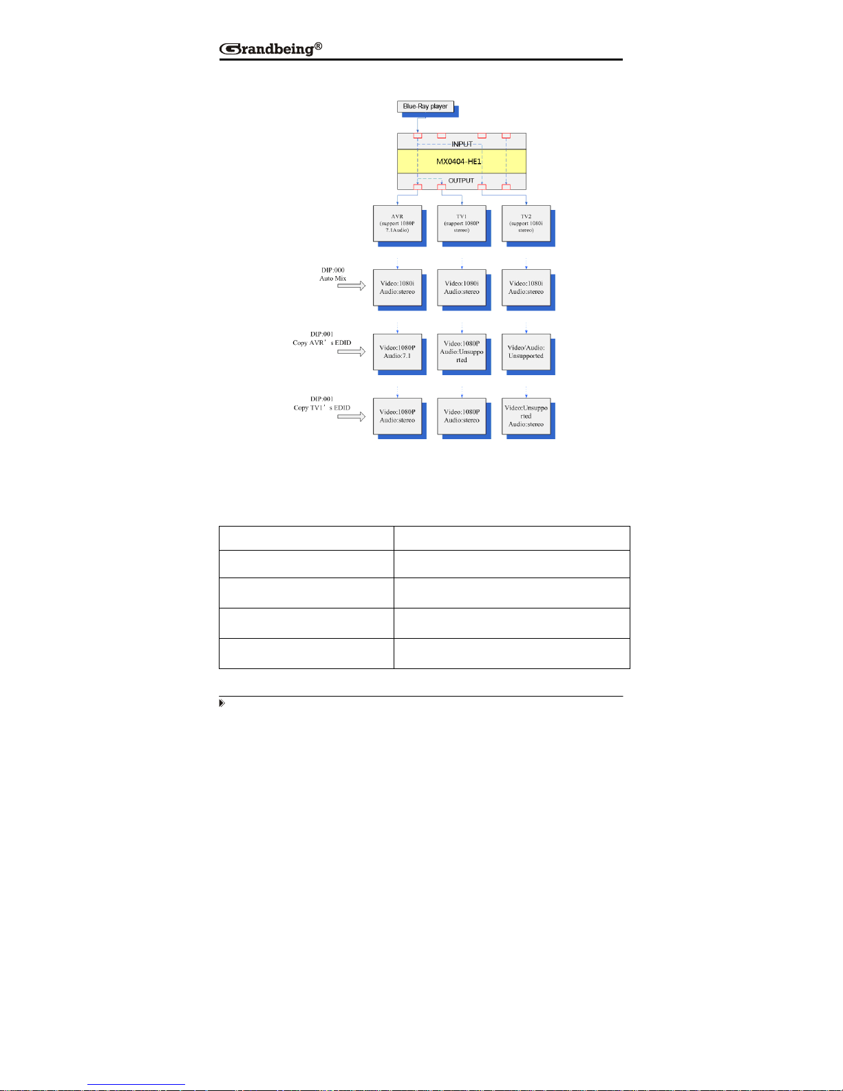
Examples for EDID setting:
1. How to reset EDID to factory default setting?
Because the default EDID is 1080p and stereo. So just set DIP to ‘010’ and power
on the matrix, all the EDID for input ports will be set to 1080p and stereo. After
reset the EDID data, the DIP switches can be set to ‘000’ or ‘001’ if user needs
future setting.
2. How to copy the EDID of AVR which is 7.1 audio to the special input port,
where connected a BD player?
1. Set DIP to ‘000’.
2. Connect the AVR to one of the output ports. For example, connect to output1.
3. Power on the matrix. Select the source of the AVR (for example input2) to the
input port which is connected to BD-player.
4. Press and hold the output1 key more than 3 seconds, the matrix will copy the
EDID data from output1 to input2.
Page 20
Page 16
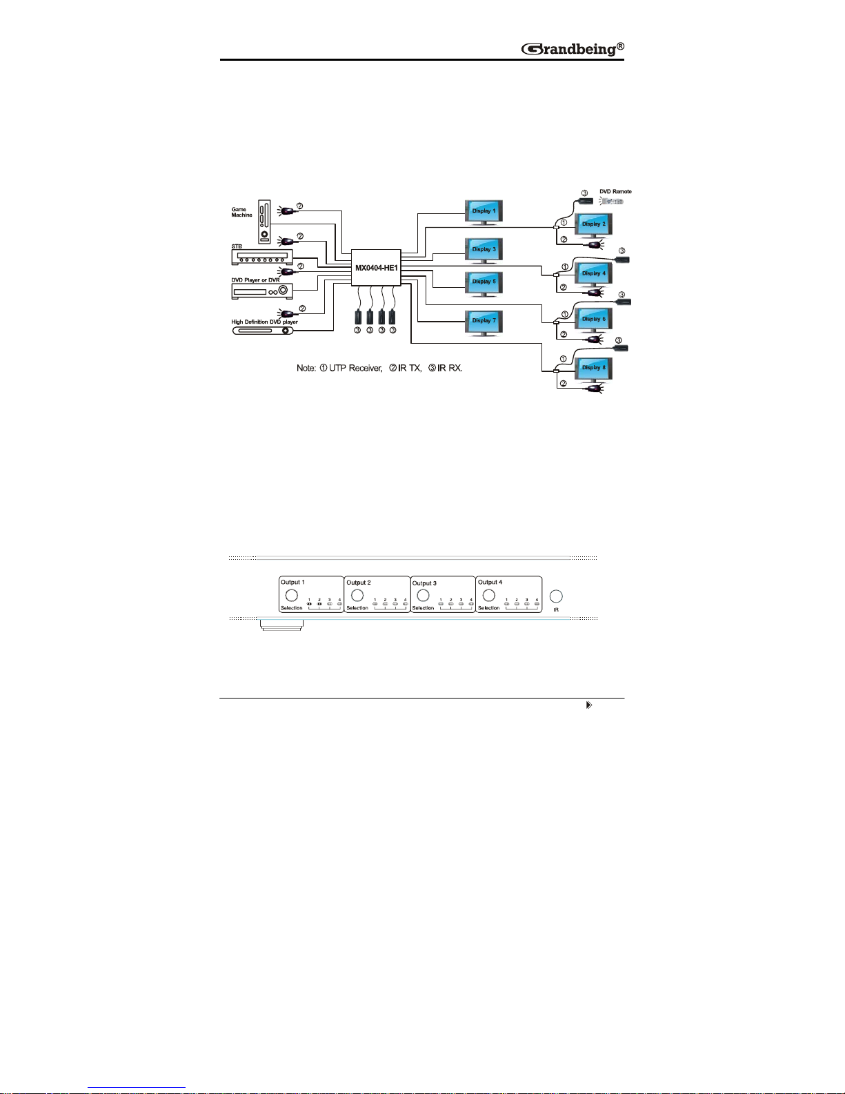
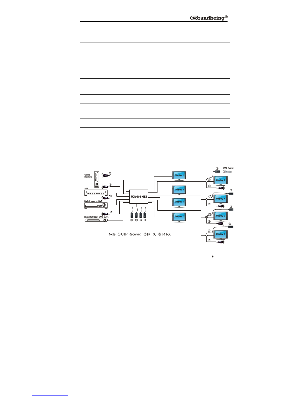
Below is the diagram for the some usage examples.
NOTE: Please insert or extract cables gently.
■ Specifications
Operating Temperature Range -5 to +35°C (-41 to +95 °F)
Operating Humidity Range 5 to 90 % RH (no condensation)
Input Video Signal 0.5-1.0 volts p-p
Input DDC Signal 5 volts p-p (TTL)
Signaling Rate 2.25Gbit/s
Page 21
Page 17
Video Format Supported
DTV/HDTV:
1080p/1080i/720p/576p/480p/576i/480i
Audio Format Supported DTS-HD/ Dolby true HD
Output Video HDMI1.2 and HDMI 1.3
Maximum Transmission
Distance
<15m (If needed, HDMI extender is
optional)
UTP cable Transmission
Distance
<70m (use Grandbeing UTP 70m receiver)
Power Consumption 35 Watts (Max.)
Dimensions
435mmL×168mmW×42mmH/17.1''L×6.6''
W×1.6''H
Mass (Main Unit) 2kg/4.4lb
NOTE: Specifications are subjected to change without notice. Mass and dimensions are
approximate.
■ Typical Application
Page 22

Page 18
■ Maintenance
Clean this unit with a soft, dry cloth. Never use alcohol, paint thinner or benzine
to clean this unit.
■ Product Service
● Provided Service
1) Damage Requiring service: The unit should be serviced by qualified
service personnel if:
z The DC power supply cord or AC adaptor has been damaged;
z Objects or liquids have gotten into the unit;
z The unit has been exposed to rain;
z The unit does not operate normally or exhibits a marked change in
performance;
z The unit has been dropped or the cabinet damaged.
2) Servicing Personnel: Do not attempt to service the unit beyond that
described in these operating instructions. Refer all other servicing to
authorized servicing personnel.
3) Replacement parts: When parts need replacing ensure the service uses
parts specified by the manufacturer or parts that have the same
characteristics as the original parts. Unauthorized substitutes may result
in fire, electric shock, or other hazards.
4) Safety check: After repairs or service, ask the service to perform safety
checks to confirm that the unit is in proper working condition.
● Mail-In Service
When shipping the unit, carefully pack and send it prepaid, adequately insured
and preferably in the original carton. Include a letter detailing the complaint and
provide a daytime phone and/or email address where yo u can be reached.
If repair is needed during the limited warranty period the purchaser will be
required to furnish a sales receipt/proof of purchase indicating date of
Page 23

Page 19
purchase, amount paid and place of purchase. Customer will be charged for
the repair of any unit received without such proof of purchase.
● Warranty
If your product does not work properly because of a defect in materials or
workmanship, Grandbeing Company (referred to as “the warrantor”) will, for
the length of the period indicated as below, (Parts (1) Year, Labor(90) Days)
which starts with the date of original purchase (“Limited Warranty period”), at
its option either (a) repair your product with new or refurbished parts, or (b)
replace it with a new or a refurbished product. The decision to repair or replace
will be made by the warrantor.
During the “Labor” Limited Warranty period there will be n o charge for labor.
During the “Parts” warranty period, there will be no charge for parts. You must
mail-in your product during the warranty period. This Limited Warranty is
extended only to the original purchaser and only cov ers product purchase d as
new. A purchase receipt or other proof of original purchase date is required for
Limited Warranty service.
● Warranty Limits and Exclusions
1) This Limited Warranty ONLY COVERS failures due to defects in
materials or workmanship, and DOES NOT COVER normal wear and
tear or cosmetic damage. The Limited Warranty ALSO DOES NOT
COVER damages which occurred in shipment, or failures which are
caused by products not supplied by the warrantor, or failures which result
from accidents, misuse, abuse, neglect, mishandling, misapplication,
alteration, faulty installation, set-up adjustments, maladjustment of
consumer controls, improper maintenance, power line surge, lightning
damage, modification, or service by anyone other than a Factory Service
Center or other Authorized Service, or damage that is attributable to acts
of God.
Page 24

Page 20
2) There are no express warranties except as listed under “limited
warranty coverage”. The warrantor is not liable for incidental or
consequential damages resulting from the use of this product, or
arising out of any breach of this warranty. (As examples, this excludes
damages for lost time, cost of having someone remove or re-install an
installed unit if applicable, travel to and from the service location, loss of
or damage to media or images, data or other recorded content. The items
listed are not exclusive, but are for illustration only.)
3) Parts and service, which are not covered by this limited warranty,
are your responsibility.
Page 25

Grandbeing Technology Co., Ltd.
Address:
6C, Jialitai Building, No. 6 Yanshan Road,
Nanshan District Shenzhen, P.R. China
Tel: 86-755-26678449
/Fax: 86-755-26678549
Post Code: 518067
www.grandbeing.biz
 Loading...