

Grand Aire WATPM Series Installation Instructions Manual
1
CONTENTS
INSTALLATION INSTRUCTIONS
These instructions are intended as an aid to qualified
licensed service personnel for proper installation, adjustment and operation of this unit. Read these instructions
thoroughly before attempting installation or operation.
Failure to follow these instruction may result in improper
installation,adjustment, service or maintenance possibly
resulting in fire, electrical shock, property damage,
personal injury or death.
1. SAFETY...............................................................................2
2. GENERAL..........................................................................3
3. APPLICATIONS.................................................................5
4. ELECTRICAL WIRING......................................................7
5. AIRFLOW PERFORMANCE.............................................9
6. DUCTWORK....................................................................10
7. REFRIGERANT CONNECTIONS.....................................10
8. AIR FILTER (not factory-installed)....................................11
9. FILTER INSTALLATION DIMENSIONS...........................12
10. WIRING..........................................................................13
PARTS
LIMITED
WARRANTY
5
YEAR
R-410A
REFRIGERANT
WATPM Series Air Handler
2-3-4-5 Ton Capacity
R410A

2
This document is customer property and is to remain with this unit.
These instructions do not cover all the different variations systems nor
does it provide for every possible contingency to be met in connection
with installtion.
All phases of this installation must comply with NATIONAL STATE
AND LOCAL CODES. If additional information is required please
contact your local distributor.
1. SAFETY
This is a safety alert symbol. When you see this symbol
on labels or in manuals, be alert to the potential for
personal injury.
This is an attention alert symbol. When you see this
symbol on labels or in manuals, be alert to the potential
for personal injury.
If removal of the blower assembly is required, all disconnect
switches supplying power to the equipment must be de-
energized and locked (if not in sight of unit ) so the field power
wires can be safely removed from the blower assembly. Failure
to do so can cause electrical shock resulting in personal injuring
or death.
WARNING
Disconnect all power to unit before installing or servicing.
More than one disconnect switch may be required to de-
energize the equipment. Hazardous voltage can cause server
personal injury or death.
WARNING
WARNING
WARNING
Because of possible damage to equipment or personal injury,
installation, service, and maintenance should be performed by a
trained, qualified service personnel. Consumer service is recom-
mended only for filter cleaning / replacement. Never operate the
unit with the acess panels removed.
WARNING
These instructions are intended as an aid to qualified, licensed
service personnel for proper installation, adjustment and opera-
tion of this unit. Read these instructions thoroughly before
attempting installation or operation. failure to follow these instruc-
tions may result in improper installation, adjustment, service or
maintenance possibly resulting in fire, electrical shock, property
damage, personal injury or death.
The unit must be permanently grounded. Failure to do so can
result in electrical shock causing personal injury or death.
WARNING
PROPOSITION 65: This appliance contains fiberglass insula-
tion. Respirable particles of fiberglass are known to State of
California to cause cancer.
All manufacturer products meet current federal OSHA Guide-
lines for safety. California Proposition 65 warnings are required
for certain products, which are not covered by the OSHA
standards.
California’s Proposition 65 requires warnings for products sold in
California that contain or produce any of over 600 listed chemi-
cals known to the State of California to cause cancer or birth
defects such as fiberglass insulation, lead in brass, and combus-
tion products from natural gas.
All “new equipment” shipped for sale in California will have
labels stating that the product contains and /or produces Propo-
sition 65 chemicals. Although we have not changed our
processes, having the same label on all our products facilitates
manufacturing and shipping. We cannot always know “when, or
if” products will be sold in the California market.
You may receive inquiries from customers about chemicals
found in, or produced by, some of our heating and air-
conditioning equipment, or found in natural gas used with some
of our products. Listed below are those chemicals and
substances commonly associated with similar equipment in our
industry and other manufacturers.
Glass Wool (Fiberglass) Insulation
Carbon Monoxide (CO).
Formaldehyde
Benzene
More details are available at the websites for OSHA
(Occupational Safety and Health Administration), at
www.osha.gov and the State of California’s OEHHA (Office of
Environmental Health Hazard Assessment), at www.oehha.org.
Consumer education is important since the chemicals and
substances on the list are found in our daily lives. Most consum-
ers are aware that products present safety and health risks,
when improperly used, handled and maintained.
3
WARNING
The first 6 inches of supply air plenum and ductwork must be
constructed of sheet metal as required by NFPA 90B. The supply
air plenum or duct must have a solid sheet metal bottom directly
under the unit with no openings, registers or flexible air ducts
located in it. If flexible supply air ducts are used they may be
located only in the vertical walls of rectangular plenum, a
minimum of 6 inches from the solid bottom. Metal plenum of duct
may be connected to the combustible floor base, if not, it must be
connected to the unit supply duct exposed to the supply air
opening from the downflow unit. Exposing combustible (non-
metal. material to the supply opening of a downflow unit can
cause a fire resulting in property damage, personal injury or
death.
Exception warning to downflow:
Installations on concrete floor slab with supply air plenum and
ductwork completely encased must be not less than 2 inches of
concrete (See NFPA 90A).
The unit can be positioned for upflow, left and right downflow
position.
This Air Handler provides the flexibility for installation in any upflow or
downflow horizontal application. The direct drive motors provides a
selection of air volume to match any application. 5-Speed motors
provide selections of air flow to meet desired applications.
Top and side power and control wiring, accessible screw terminals for
control wiring all combine to make the installation easy, and minimize
installation cost. See fig.1.
2. GENERAL
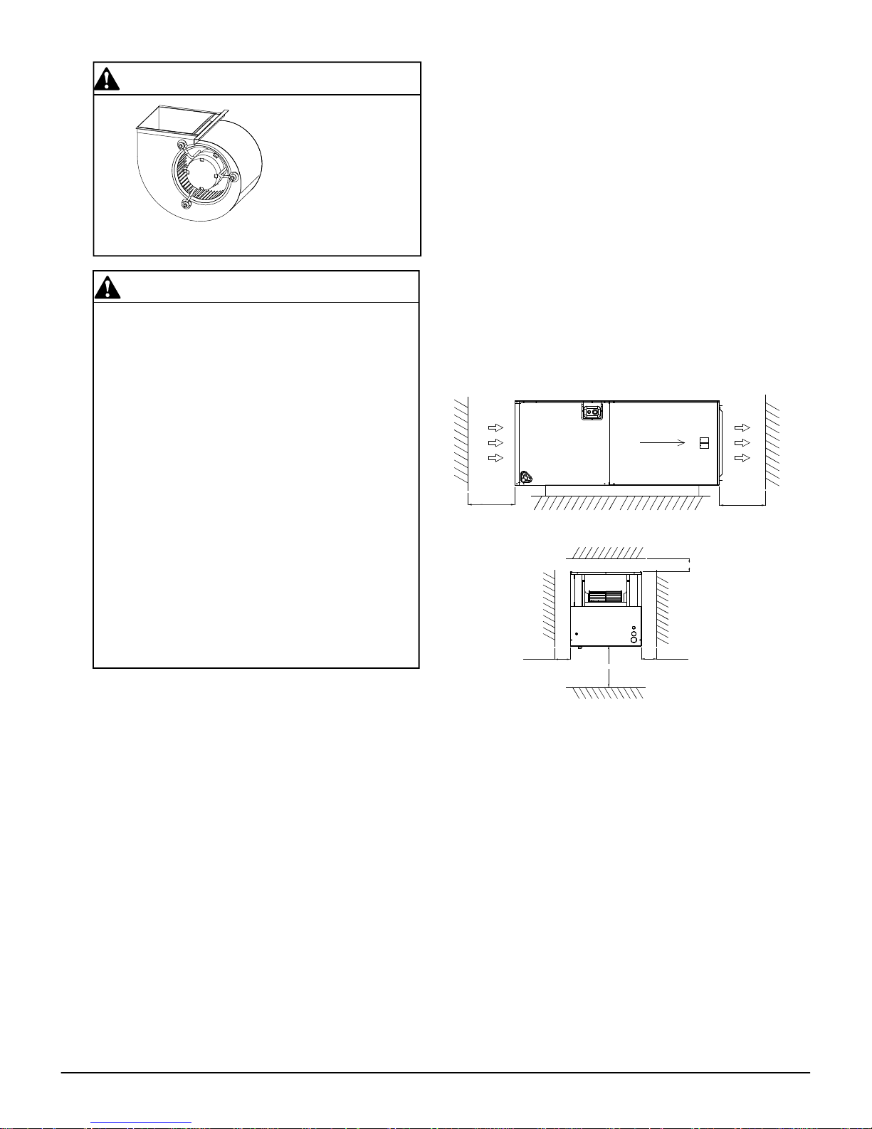
CAUTION
Make sure the blower
morot support is tight(3-
motor mount bolts) then
check to see if wheel is
secured to motor shaft
before operating unit.
To ensure the proper installation, select a solid and level site.
Ensure enough space maintained for installation and maintenance.
≥40’’
≥
25’’
≥40’’
≥0
≥0
≥0
AIRF LOW
Front of unit
Clearances in the Horizontal Position
Clearances in the Vertical Position
4
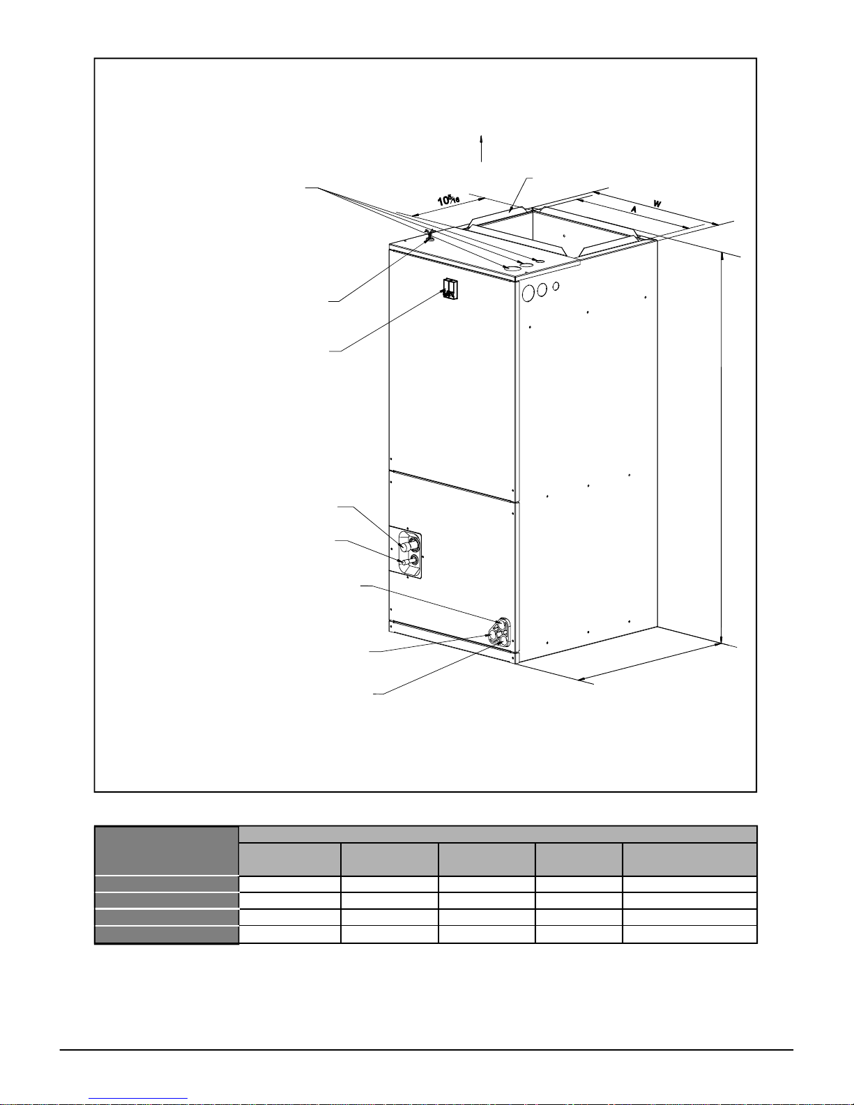
2.1 UNIT DIMENSIONS
UPFLOW UNIT SHOWN;
UNIT MAY BE INSTALLED UPFLOW, DOWNFLOW,
HORIZONTAL RIGHT, OR LEFT AIR SUPPLY.
24
36
48
54-1/2"[1385] 22"[560] 24"[610]
19-1/2"[496]
54-1/2"[1385] 22"[560] 24"[610]
19-1/2"[496]
60 54-1/2"[1385] 22"[560] 24"[610] 19-1/2"[496]
MODEL SIZE
Dimensions inch [mm]
SUPPLY
DUCT "A"
UNIT HEIGHT
"H" IN. [mm]
UNIT WIDTH
"W" IN.[mm]
UNIT LENGHT
"D" IN.[mm]
LIQUID LINE /
VAPOR LINE
4
6-1/2"[1180] 19-5/8"[500] 21-5/8"[550] 18"[456]
Fig.1 DIMENSIONS
W
A
1
0
5
1
6
NOTE: 25” CLEARANCE IS REQUIRED IN THE FRONT
OF THE UNIT FOR FILTER AND COIL MAINTENANCE.
SUPPLY AIR
FLANGES ARE PROVIDED
FOR FIELD INSTALLATION
ELECTRICAL CONNECTIOS
MAY EXIT TOP OR EITHER SIDE
HIGH VOLTAGE CONNECTION 7/8”,
1-3/8”, 1-3/4” DIA KNOCK OUTS
LOW VOLTAGE CONNECTION
BREAKER SWITCH
(FOR ELECTRIC HEATER ONLY)
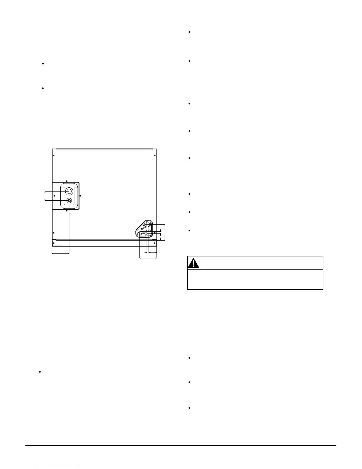
VAPOR LINE CONNECTION COPPER (SWEAT)
LIQUID LINE CONNECTION COPPER (SWEAT)
AUXILIARY DRAIN CONNCECTION 3/4”
FEMALE PIPE THREAD (NPT)
AUXILIARY DRAIN CONNECTION 3/4”
FEMALE PIPE THREAD (NPT)
PRIMARY DRAIN CONNCETION 3/4”
FEMALE PIPE THREAD (NPT)
DIMENSIONAL DATA
H
D
3/8" / 3/4"
[9.5]/[19]
3/8" / 3/4"
[9.5]/[19]
3/8" / 7/8"
[9.5]/[22]
3/8" / 7/8"
[9.5]/[22]
1-9/16
2-15/16
5/16
2-15/16
1-3/8
1-1/4
5/16
2-13/16
3.2 VERTICAL DOWNFLOW
Conversion to Vertical Downflow: A vertical upflow unit may be
converted to vertical downflow. Remove the door and indoor coil and
reinstall 180
°
from original position. See Fig 3.
IMPORTANT: To comply with certification agencies and the National
Electric Code for downflow application, the circuit breaker(s) on field-
installed electric heater kits must be re-installed per procedure below
so that the breaker switch “on” position and marking is up and, “off”
position and marking is down.
To rotate breaker(s): Rotate one breaker set (circuit) at a time
starting with the one on the right. Loosen both lugs on the load
side of the breaker. (Make sure that wires are identified and are
reinstalled into proper breaker).Wires are bundles with wire ties,
one bundle going to the right lug and one bundle going to the left
lug.
Using a screwdriver or pencil, lift white plastic tab with hole
away from breaker until breaker releases from mounting
opening.
With breaker held in hand, rotate breaker so that “on” position
is up, “off” position is down with unit in planned vertical mount-
ing position. insert right wire bundle into top right breaker lug,
ensuring all strands of all wires are inserted fully into lug, and
no wire insulation is in lug.
Tighten lug as tight as possible while holding circuit breaker.
Check wires and make sure each wire is secure and none are
loose. Repeat for left wire bundle in left top circuit breaker lug.
Replace breaker by inserting breaker mounting tab opposite
white pull tab in opening, hook mounting tab over edge in
opening.
With screwdriver or pencil, pull blue tab with hole away from
breaker while setting that side of breaker into opening. When
breaker is in place, release tab, locking circuit breaker into
location in opening.
Repeat above operation for remaining breaker(s) (if more than
one is provided).
Replace single point wiring jumper bar, if it is used, on line side
of breaker and tighten securely.
Double check wires and lugs to make sure all are secure and
tight. Check to make sure unit wiring to circuit breaker load lugs
match that shown on the unit wiring diagram.
5
3 APPLICATIONS
3.1 VERTICAL UPFLOW
Vertical Upflow configuration is the factory set on all models (see
Fig 1).
If return air is to be ducted, install duct flush with floor.
Use fireproof resilient gasket 1/8 to 1/4 in. thick between the
ducts, unit and floor. Set unit on floor over opening.
Horizontal right is the default factory configuration for the units.
Conversion to Horizontal left: A vertical upflow unit may be
converted to horizontal left by removing indoor coil assembly and
reinstalling coil as shown for left hand air supply.
Rotate unit into the downflow position, with the coil compartment
on top and the blower compartment on bottom. See Fig. 3
Reinstall the indoor coil 180° from original position. Ensure the
retaining channel is fully engaged with the coil rail. See Fig. 3.
Secondary drain pan kits are recommended when the unit is
configured for the horizontal position over a finished ceiling
and/or living space.
Fig.2 DIMENSIONS FOR FRONT CONNECT COIL
CAUTION
When using the unit with electrical heater, the switch on the front
of panel is used only for electrical heater.
IMPORTANT NOTE
Torque applied to drain connections should not
exceed 15.ft.lbs.(see Fig.1&2)
3.3 HORIZONTAL
 Loading...