

Grandaire Pinnacle Series, WATPM Series, WATPM364A1, WATPM244A1, WATPM604A1 Product Specifications
...
Product Specifications
WATPM Series Air Handler
2-3-4-5 Ton Capacity
R410A
Air Handler Features
Multi-speed ECM blower motor.
Factory-installed TXV metering.
Multipositlon Installation -.upflow or horizontal right standard;
field convertible to horizontal left or downflow.
Multiple electrical entry locations.
Field Installed heater kits 5, 8, 10, 15, 20KW available as an accessory.
Dual front panel design for ease of maintenance.
Blower and coil easy slide out design for ease of maintenance.
Fully-insulated cabinet design.
Horizontal and vertical condensate drain pans standard.
Condensate drain pan is polymer with UVC inhibitor.
Primary and secondary condensate drain fittings.
Factory-sealed cabinet certified to achieve 2% or less
leakage rate at 1.0 inch water column.
Integrated filter rack with tool-less door access.
AHRI and ETL Listed.
Contents
Nomenclature...................................................... 2
Product Specifications......................................... 3
Dimensions ......................................................... 4
Blower Data......................................................... 5
Heater Kit Data ................................................... 6
Wiring Diagram.................................................... 7
Parts List...............................................................9
5
YEAR
PARTS
LIMITED
WARRANTY
R-410A
REFRIGERANT
1

Nomenclature
PRODUCT SPECIFICATIONS
FAN COIL MODEL NUMBER IDENTIFICATION GUIDE
Digit Position:
Example Part Number:
WA = Air Handler
T = TXV
E = EEV
P = High Efficency ECM Motor
S = PSC Motor
L = Aluminum Tube,Aluminum
Fin Evaporator Coil
M = Copper Tube,Aluminum
Fin Evaporator Coil
24 = 24000BTU/hr = 2 tons
36 = 36000BTU/hr = 3 tons
48 = 48000BTU/hr = 4 tons
60 = 68000BTU/hr = 5 tons
4 = R-410A
Sales Code
1,2 3 5 6,7 8 1094
WA T P M 24 4 A 1
MOTOR TYPE
INSTALLATION TYPE
NOMINAL COOLING CAPACITY
REFRIGERANT
Extra Digit
2

Product Specifications
Specifications
WATPM244A1 WATPM364A1 WATPM484A1 WATPM604A1
Cooling Capacity
Nominal Cooling (BTU/h)
Nominal Heating (BTU/h)
Blower
Diameter
Width
Fan Motor
Horsepower (HP) 1/3 1/2 3/4
FLA
Refrigeration System
Refrigerant Line Size¹
Liquid Line Size (“O.D.)
Suction Line Size (“O.D.)
Refrigerant Connection Size
Liquid Valve Size (“O.D.) ⅜" ⅜" ⅜"
Suction Line Size (“O.D.)
Expansion Device TXV TXV TXV
Decibels
High dB(A)
Medium dB(A)
Low dB(A)
24,000 34,600 47,000
24,000 33,600 46,500
10⅝" 11"
8" 10⅝"
2.8 4.1 6.0
⅜"
¾"
¾"
62 67
59
55
⅜" ⅜"
¾" ⅞"
¾" ⅞" ⅞"
64
60
56
11"
10⅝"
63
59
57,000
55,000
11"
10⅝"
3/4
6.0
⅜"
⅞"
⅜"
TXV
68
64
60
Electrical Data
Voltage-Phase-Hz 208/230-1-60 208/230-1-60 208/230-1-60
Minimum Circuit Ampacity ²
Max. Overcurrent Protection
Min / Max Volts 187 / 253 187 / 253 187 / 253
Air Filter Sizes
Equipment Weight (lbs)
Ship Weight (lbs)
1 Tested and rated in accordance with AHRI Standard 210/240
2 Wire size should be determined in accordance with National
Electrical Codes; extensive wire runs will require larger wire sizes
3 Must use time-delay fuses or HACR-type circuit breakers of the same size as noted.
3
3.5 5.1 7.5
15 15 15
18’’ x 20’’ 20’’ x 22’’ 20’’ x 22’’ 20’’ x 22’’
119 161 162
132 178 180
208/230-1-60
7.5
15
187 / 253
170
188
3
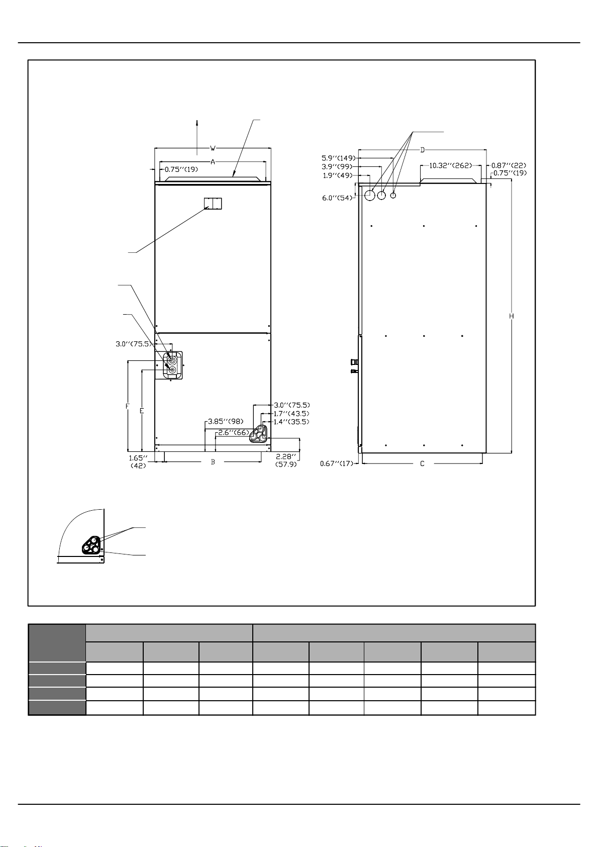
Dimensions
NOTE: 25” CLEARANCE IS REQUIRED IN THE FRONT
OF THE UNIT FOR FILTER AND COIL MAINTENANCE.
BREAKER SWITCH
( ELECTRIC HEATER ONLY)
VAPOR LINE COPPER
LIQUID LINE COPPER
SUPPLY AIR
FLANGES ARE PROVIDED
FOR FIELD INSTALLATION
HIGH VOLTAGE CONNECTION 7/8”,
1-23/64”, 1-23/32” DIA KNOCK OUTS
INLET
(FRONT VIEW)
AUXILIARY DRAIN CONNECTION 3/4”
FEMALE PIPE THREAD (NPT)
PRIMARY DRAIN CONNCETION 3/4”
FEMALE PIPE THREAD (NPT)
Fig.1 DIMENSIONS
MODEL SIZE
24
36
48
60 54½"[1385] 22"[560] 24"[610] 19½"[496]
"H" IN. [mm] "W" IN.[mm]
46½"[1180] 19⅝"[500] 21⅝"[550] 18"[456]
54½"[1385] 22"[560] 24"[610]
54½"[1385] 22"[560] 24"[610]
"D" IN.[mm] "A" IN.[mm] "B" IN.[mm] "C" IN.[mm] "E" IN.[mm] "F" IN.[mm]
19½"[496]
19½"[496]
INLET
(RIGHT SIDE VIEW)
Dimensions inch [mm]Dimensions inch [mm]
16⅓"[416]
18¾"[476]
18¾"[476] 22¾"[576] 19⅓"[492] 21"[532]
18¾"[476] 22¾"[576] 19⅓"[492] 21"[532]
20⅓"[516]
22¾"[576]
13¾"[350]
19⅓"[492]
15⅓"[390]
21"[532]
4
 Loading...