


Voice Broadband Optical Multiplexer User Manual
1
Table of contents
CHPATER 1 GENERAL INFORMATION ....................................... 3
1.1 INTRODUCTION ......................................................................... 3
1.2 FEATURES ................................................................................. 3
CHPATER 2 FUNCTION DESCRIPTION ....................................... 5
2.1 FRONT PANEL ........................................................................... 5
2.1.1 Front Panel LED Indicators .............................................. 5
2.1.2 CONSOLE Interface ........................................................ 6
2.1.3 Fiber Interface .................................................................. 6
2.2 FUNCTION CARD REAR PANEL ................................................. 6
CHAPTER 3 TECHNICAL SPECIFICATIONS ............................... 8
3.1 OPERATING ENVIRONMENT ...................................................... 8
3.2 POWER SUPPLY ......................................................................... 8
3.3 MECHANICAL SPECIFICATION ................................................... 8
3.4 OPTICAL INTERFACE ................................................................. 8
3.5 E1 INTERFACE CRITERIA .......................................................... 8
3.6 ETHERNET INTERFACE .............................................................. 9
3.7 SERIAL INTERFACE (RS232/RS485/RS422) DATA INTERFACE .. 9
3.8 FXO (FXS) TELEPHONE INTERFACE......................................... 9
CHAPTER 4: INSTALLATION ...................................................... 10
4.1 SAFETY REQUIREMENTS ......................................................... 10
4.2 INSPECTION UPON UNPACKING ............................................... 11
4.3 POWER SUPPLY ....................................................................... 11
4.4 TEST ....................................................................................... 11
4.5 CONFIGURATION AND CONNECTION ....................................... 11
CHAPTER 5 APPENDIX ............................................................... 12
5.1 HOW TO MAKE THE CABLE ...................................................... 12
5.1.1 How to make E1 connecting cable ................................. 12
5.1.2 How to make Ethernet interface connecting cable ......... 12
5.1.3 How to make serial (RS232/485/422) interface
connecting cable ...................................................................... 13
5.1.4 How to make voice interface connecting cable .............. 14
5.1.5 How to make CONSOLE interface connecting cable .... 14
5.2 FAILURE DIAGNOSES AND TROUBLESHOOTING ....................... 14
5.3 WARRANTY CARD .................................................................. 16

Voice Broadband Optical Multiplexer User Manual
2
Preface
Version Description
Manual version: 1.0 (V1.0)
Copyright Notice
The copyright of this manual is reserved to our company, who
retains the final rights of explanation and revision to this manual and notice.
No part of this manual may be photocopied, excerpted, reproduced, revised,
transmitted, translated into other languages, or used for commercial purpose
in full or in part, without the prior written permission of the Company.
Disclaimer
This manual is made according to currently available information
and subject to change without further notice. Whilst every effort has been
made to ensure the accuracy and reliability of the contents contained herein,
the Company cannot be held liable for any harm or damage resulting from
any omissions, inaccuracies or errors contained in the manual.
Brief Introduction
This User Manual describes the installation and operation of
OP-4E1+ETH+32Vo. Before you use our device for the first time, please
read all the included materials carefully, and install and operate this series of
products in keeping with items listed in the manual, so as to avoid damaging
the device resulting from malpractice. Thank you for choosing our products.
Environmental Protection
This product complies with the design requirements
associated with environmental protection. The storage, use and
disposal of the product should be conducted in accordance with
related national laws and regulations.
We welcome you to put forward advice and suggestion
to our work, which shall be viewed as the ultimate support to
us.

Voice Broadband Optical Multiplexer User Manual
3
Chpater 1 General Information
1.1 Introduction
OP-4E1+ETH+32Vo is a new generation highly-integrated
single-board PCM base group multi-connection equipment based
on independent software and thick & thin film technology. It can
provide a 4~32-line voice interface directly upon the optical
transmission channel with a 4-line E1 interface, a 4-line(100M
shared) Ethernet data interface. Voice Broadband Optical
Multiplexer is mainly used in implementing connections between
telephones and SPC exchanges through transmission network, as
well as providing various kinds of data operation interfaces.
The device is widely used in: places such as telephone bars,
middle and small scale companies, expressways and some
temporary construction sites which demand quick solutions to the
need of telephone and data operation, and the “Village-village
Connection” telephone accessing project which is now in
progress.
1.2 Features
High-density single-board design, improved system
reliability, easy installing&commissioning, maintenance free
and stable performance.
Fiber interface provides optical circuit E
-3
and E-6 bit error
warning detection, indicating circuit quality for builders and
helping circuit maintenance.
4-line E1 interface to help extend telephone interfaces or
other video transmission.
32-line telephone interface, traditional PSTN voice,
uncompressed, with high voice quality. Caller ID function
available.
4-line Ethernet interface with 100M bandwidth. Optional
10M/half duplex, 10M/full duplex, 100M/half duplex,
100M/full duplex and self adaptative.
Peer-to-peer networking mode, FXO/FXS mode supported.
Fixed the telephone transmission problems of marginal
customers.

Voice Broadband Optical Multiplexer User Manual
4
1.9 inches structure with 1U height supported, high
single-machine density, and lower machine room occupancy.

Voice Broadband Optical Multiplexer User Manual
5
Chpater 2 Function Description
2.1 Front Panel
PWR
SYL
E
6
E
1
L
2
ACT1ACT
2
SYS
DUP1DUP
2
SPD
1
SPD
2
E
1
L
1
LOS
E
3
V
1
V
3
V
5
V
7
V
9
V11V
13
V
15
V
17
V
19
V
21
V23V
27
V
25
V
29
V
31
V
2
V
4
V
6
V
8
V10V
12
V
14
V16V
18
V
20
V22V24V28V26V30V
32
CONSOLE
TX RX
Fiber Port
E
1
L
4
E
1
L
3
ACT
4
DUP3DUP
4
SPD3SPD
4
ACT
3
(Figure of Front Panel)
2.1.1 Front Panel LED Indicators
There are 52 LED indicators with different functions at the front
panel. Their functions are described as follows:
Name
Color
Function
Description
PWR
Green
Indication of power supply status
on
Power supply is OK.
off
No power input.
SYS
Yellow
Indication of operating
on
In normal operation.
off
Not in operation.
SYL
Red
Indication of loss of frame in
optical link
on
Alarming of loss of frame
in optical link.
off
In normal operation.
LOS
Red
Indication of loss of signal in
optical link
on
Alarming of loss of signal
in optical link.
off
In normal operation.
E6
Yellow
Error signal in optical link≥10-6
on
Error signal in optical
link≥10
-6
off
In normal operation.
E3
Red
Error signal in optical link≥10-3
on
Error signal in optical
link≥10
-3
off
In normal operation.
E1L1-4
Red
Indication of E1 1-4 working
status
on
Loss of signal in E1 1st
off
In normal operation.
Voice Broadband Optical Multiplexer User Manual
6
ACT1-4
Green
Indication of connection and
activities of Ethernet 1-4
on
Ethernet connected
properly
off
Connection off
flash
Data packet transferring
DUP1-4
Green
Indication of full/half duplex of
Ethernet 1-4
on
Full duplex
off
Half duplex
SPD1-4
Green
Indication of operation speed of
Ethernet 1-4
on
100M
off
10M
V1~32
Green
Indication of operation status of
voice 1st~32nd
on
Picked up
off
Stand by
on for
1s and
off for
4s
Ringing
2.1.2 CONSOLE Interface
Operating parameters of local and remote end devices can
be configured through CONSOLE interface, and meanwhile
operating status of local and remote end devices can be
acquired.(Currently unavailable in this version.)
2.1.3 Fiber Interface
RX: Receiving optical signal TX: Sending optical signal
Various kinds of optical interfaces of different physical mode are
available to satisfy customer’s need.
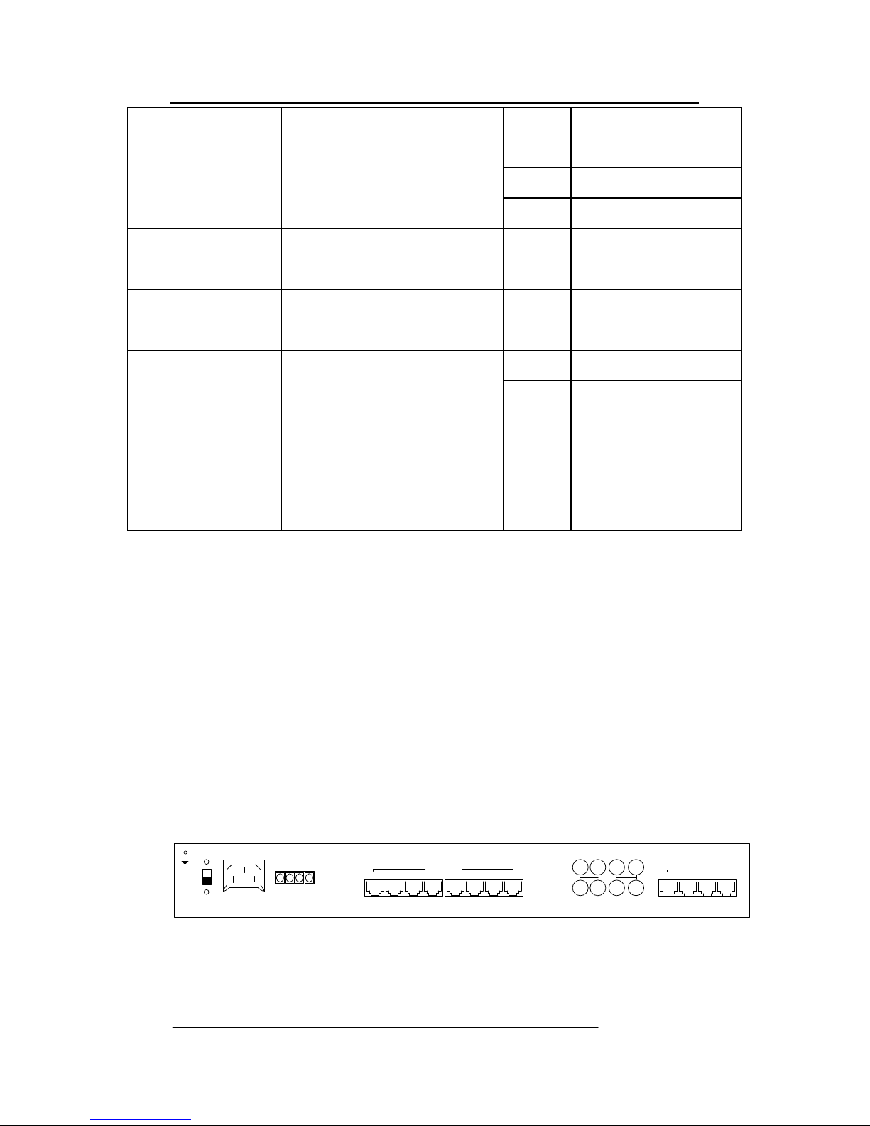
2.2 Function Card Rear Panel
1-4 5-8 9-12 13-16 1-4 5-8 9-12 13-16
AC220V
OFF
-
DC48V
+
ON
Ethernet
1 2 3 4
RX1 RX2 RX3 RX4
TX1 TX2 TX3 TX4
E1 75Ω
VOICE
(Figure of Rear Panel-75Ω)

Voice Broadband Optical Multiplexer User Manual
7
1-4 5-8 9-12 13-16 1-4 5-8 9-12 13-16
AC220V
OFF
-
DC48V
+
ON
Ethernet
1 2 3 4
VOICE
E1 120Ω
1 2 3 4
(Figure of Rear Panel-120Ω)
2.2.1 E1 Interface
4-line E1 interface on rear panel, next to voice interface is E1 of
1st line.
75Ω/RX: 75Ω unbalanced E1 signal input.
75Ω/TX: 75Ω unbalanced E1 signal output.
2.2.2 Ethernet Interface (100M Bandwidth)
There are 4 connecting RJ45 ports on rear panel, and the two
connecting ones on the right are the Ethernet interface, which are
switch-mannered. The Ethernet interface supports automatic
recognition/adaptation of cross-wires and direct-type-wires,
ridding the trouble of remaking the wires.
2.2.3 VOICE Interface
There are 8 RJ45 ports in a row that are the voice interface,
each of which can transfer 4 lines of telephone, making 1~4, 5~8,
9~12, 13~16, 17~20, 21~24, 25~28, 29~32 from left to right.
Connect in order depending on the number of ways ordered by
customer.
2.2.4 Power Supply
The power supply has two options: AC and DC, which
should be specified upon ordering, and a universal version is also
available. The device supports two power versions: 220V and
–48V, with up to 20% fluctuation. Note that the DC power supply
has positive and negative poles. The negative/positive pole of
–48V power source should be plugged into the negative/positive
pole of the power input on the device. The power is off when
the switch is on “OFF” position. Otherwise the power is on.

Voice Broadband Optical Multiplexer User Manual
8
Chapter 3 Technical Specifications
3.1 Operating Environment
The device has a wide range of operating temperature and is
able to work normally and stably in highly adverse environment.
Operating Temperature: 0℃ ~ +50℃
Storage Temperature: -40℃ ~ +70℃
Relative Humidity: 10 %~95 %
Atmospheric Pressure: 70~106 kpa
The environment should be free of corrosive and solvent
gases, dust, and magnetic interference.
3.2 Power Supply
Using high-quality power adaptor, the device has a wide
fluctuation tolerance, strong anti-interference and isolation
quality to ensure a stable operation.
Input Voltage AC 220V / DC-48V
Power Fluctuation 165VAC~265VAC or -36VDC~-
72VDC
Power Consumption <50 W (The power consumption will
vary in result of the quantity difference of voice configurations)
3.3 Mechanical Specification
Dimensions: 430mm Width ×44mm Height ×203mm Depth
3.4 Optical Interface
Wavelength: 850, 1310 or 1550nm optional
Mean Transmit Power: ≥-8dBm(single mode, 1310)
≥-18dBm(multimode, 850)
≥-25dBm(multimode, 1310)
Receiver Sensitivity: ≤-36dBm
Connector Type: FC/SC optional; single mode/multimode
optional; single-strand/dual-strand optional.
3.5 E1 Interface Criteria
Electrical Performance: compatible with ITU-T G.703
Transfer Performance: compatible with ITU-T G. 823
Jitter Performance: compatible with ITU-T G. 823
Code Type: HDB3
Interface Impedance: 75Ω/120Ω

Voice Broadband Optical Multiplexer User Manual
9
Interface Connector: Q9 (75Ω)
3.6 Ethernet Interface
Ethernet Interface Rate: 10M/100M adaptive, 10M
half-duplex, 10M full-duplex, 100 M half-duplex or 100M
full-duplex optional
Compatible Portocol: IEEE802.3
Transmission Rate: 100M
3.7 Serial Interface (RS232/RS485/RS422) Data Interface
Transmission Rate: ≤115.2kbps Adaptive
Transmission Type: Asynchronous
Interface Connector: RJ45
3.8 FXO (FXS) Telephone Interface
Line Property: Comply with the Technical specifications for
telephone exchange equipment by Ministry of Posts and
Telecommunications
Voice encoding: PCM encoding, 64Kbps per line
Relay Interface (FXO): Connected to switch
Second-tier AC input impedance: 200+680//104Ω(three
components)
Ringing voltage: 35~90V
Ringing frequency: 17 ~ 60 HZ
Return Loss: 30~40 db
User Interface (FXS): connect users’ telephone
Second-tier AC input impedance: 200+680//104Ω(three
components)
Loop Resistance of Subscriber Line: ≥1KΩ(including the
phone)
Ringing voltage-peak: 60~80V
Ringing frequency: 17 ~ 60 HZ
Feed voltage: 48 V
Return Loss: 30~40 db
Interface type: RJ45

Voice Broadband Optical Multiplexer User Manual
10
Chapter 4: Installation
4.1 Safety Requirements
Please read the following safety items before installation to avoid
physical injury and damage to this product or any other products connected.
To avoid potential hazard, the product can be used only within specified
scope. Maintenance can be conducted only by technical personnel
authorized by our company.
1. Avoid fire or physical injury.
2. All power supply should be shut off during installation, which can be
turned on only when all terminals have been connected correctly and
checked to be free from mistakes.
3. Connect and disconnect in a properly. When device is powered up, do not
connect or disconnect data cable without due cause.
4. Grounding. The product should be linked to the ground through earthed
conductor. To avoid electric shock, the earthed conductor must be in
connection with the ground. Make sure that the product is correctly earthed
before connecting with the input or output terminals.
5. Correct connection. Users are expected to use accompanied accessories.
In the event that special connections are needed, please pay attention to the
corner allocation requirements.
6. Don’t operate when there is no cover plate over the device. Do not
operate the product if the cover plate or panel has been dismounted.
7. No contact with bare circuit is allowed. Do not touch bare connectors or
components when power is on.
8. No operation is allowed if there is suspicion of failure. Call authorized
maintenance personnel for examination and reparation should the product be
suspected of damage.
9. Good ventilation. Do not operate under humid or explosive environment.
10. Maintain the surface of the product clean and dry.

Voice Broadband Optical Multiplexer User Manual
11
11. Do not point the optical header toward eyes, lest that laser injures the
retina.
4.2 Inspection upon Unpacking
After unpacking the product, inspect the type, quantity and condition of
device and accessories inside according to the list of contents specified in
this manual. Contact the Company or its distributors and agencies
immediately should abnormal circumstances arise.
4.3 Power Supply
Check the power supply of the device. The power input
should be configured in accordance with related requirements.
Pay particular attention to the voltage and polarity if the power
supply is DC. Before you plug and unplug the power cable,
please disconnect the power supply. Connect the power
supply again after operation. And use the equipment under
the operating condition required in the manual.
4.4 Test
The following tests should be conducted before use:
1. After the device is powered up correctly, check whether
PWR, LOS, E1L1, E1L2, E1L3, E1L4 and SYS are on, and the
rest LED indicators are off.
4.5 Configuration and Connection
If indicators work correctly as described in 5.4, turn off the
power, configure operating modes based on the overall
requirements of network environment, plug on E1 cable and
optical fibers, and then turn on the power. The device will enter
into normal operation.
If the device fails to work properly as described in 4.4, see
failure diagnoses and troubleshooting section of the manual. If
the failure still exists, contact the Company or its distributors and
agencies immediately.

Voice Broadband Optical Multiplexer User Manual
12
Chapter 5 Appendix
5.1 How to make the cable
5.1.1 How to make E1 connecting cable
75Ω mode: 120Ω mode:
Core connects with core, The Pinout of 120Ω
mode are
Sheath connects with connects, and illustrated below
Core is isolated from sheath.
1, 2, 3, 4, 5, 6, 7, 8
5.1.2 How to make Ethernet interface connecting cable
Ethernet interface adopts twisted pair cable. There are two
international standards on how to make it, which are
EIA/TIA568A and EIA/TIA568B. Put the connector tail down
(that is, flat side up), from left to right, enumerating as 1 2 3 4 5 6
7 8, respectively. The following is the allocation of lines:
The twisted pair specification of RJ-45 is provided as follows:
(EIA/TIA568A Standard)
(EIA/TIA568BStandard)
Pin
Connecting signal
Twisted-Pair
Pin
Connected signals
Twisted-pair
1
TX+(Transmit)
White-Green
1
TX+(Transmit)
White-Orange
2
TX-(Transmit)
Green
2
TX-(Transmit)
Orange
3
RX+(Receive)
Orange
3
RX+(Receive)
White-Green
4
Not Applicable
Blue
4
Not Applicable
Blue
5
Not Applicable
White-Blue
5
Not Applicable
White-Blue
6
RX-(Receive)
Orange
6
RX-(Receive)
Green
7
Not Applicable
White-Brown
7
Not Applicable
White-Brown
8
Not Applicable
Brown
8
Not Applicable
Brown
1(+)、 2(-)are output pins
4(+)、 5(-)are input pins

Voice Broadband Optical Multiplexer User Manual
13
1) 1 and 2 are used for sending, 3 and 6 for the receiving, and 4, 5,
7 and 8 are two-way lines.
2) 1 and 2 must be twisted pair, 3 and 6 twisted pair, 4 and 5
twisted pair, and 7 and 8 twisted pair.
Straight-through cable: Both ends are connected according to the
T568 sequence standard.
Cross-line cable: one end uses the sequence of T568A, the other
end uses line sequence T568B connection. Specific link:
1) Connect the equipment with PC or router directly: use
straight-through cable, the connect method of two ends are the
same
2) Connect the equipment and switches (or HUB) cascadly: use
cross-line cable, the connect method of two ends are different.
Cross-line cable: one end uses the sequence of T568A, the other
end uses line sequence T568B connection. Specific link:
5.1.3 How to make serial (RS232/485/422) interface
connecting cable
Provide two RJ45 interfaces, each one can provide two
RS232/485/422 interfaces; the specific line sequence is as
following:
Pin
RS232Definition
RS485 Half
Duplex
RS485Duplex
RS422Definition
1
RS232Input
2
ON(Fixed Output
Effective Signal)
3
RS232 Output
4
GND
GND
GND
GND 5
DATA+
TXD+
TXD+
6 DATA-
TXD-
TXD- 7
RXD+
RXD+ 8
RXD-
RXD-

Voice Broadband Optical Multiplexer User Manual
14
1,2,3,4,5,6,7,8
5.1.4 How to make voice interface connecting cable
8 RJ45 interfaces provide 32 lines of telephone; each one
provides four lines,
Pin
Definition
[1..2]
Voice Line1
[3..4]
Voice Line2
[5..6]
Voice Line3
[7..8]
Voice Line4
5.1.5 How to make CONSOLE interface connecting cable
Pin
Definition
1
RS232Input
2
Empty
3
RS232Output
4
GND
5.2 Failure Diagnoses and Troubleshooting
Symptom
Possible Cause
Remedy
PWR is OFF
1. Control switch is not fully turned on.
2. The power supply is not connected
with correct polarity.
3. Outside power source is not correctly
plugged.
4. Conductor is dropped into the frame,
causing short-circuits between power
source and the ground.
5. Failure at power supply module.
1. Fully turn on the control switch.
2. Swap the polarity connection.
3. Properly plug the outside power source.
4. Remove the conductor.
5. Contact the distributor.
LOS and SYL
alarm after the
optical interface are
1. The RX and TX are reversed at
optical interface.
2. The cable is not made properly.
1. Swap RX and TX.
2. Make the cable properly.
3. Set the transmission distance based

Voice Broadband Optical Multiplexer User Manual
15
connected.
3. The transmission distance
exceeds specifications of the
ordered product.
4. Failure at optical interface
module.
on specifications of the ordered
product.
4. Contact the distributor.
Ethernet can be
pinged, but there is
packet loss.
1. The network cable is not
twisted-pair
2. The cascade of HUBER is too
much
3. Operating mode is not correct
4. The device clock is not
configurated properly on the
datalink.
1. Make the connecting cable properly
2. Change the network structure to
reduce the multiple cascades of
HUBER
3. Set proper operating mode
4. Set other device clock mode on the
line
E1 line alarms after
the E1 interface is
connected.
1. The RX and TX are reversed at
E1 interface.
2. The E1 connecting cable is not
properly made.
3. The transmission distance
exceeds specified value.
1. Swap RX and TX.
2. Make the E1 connecting cable
properly.
3. 75Ω: 300M 120Ω:500M
The telephone noise
is too intense.
1. The voice line is not in
the distribution frame, the
contaction is loose;
2. The contaction of
telephone line connected
to the telephone is bad.
1. Check the distribution frame and
fasten the lines;
2. Re-make the telephone line;

Voice Broadband Optical Multiplexer User Manual
16
5.3 Warranty Card
The Company guarantees:
1. Maintenance Service
(1) Within the free-of-charge warranty period (12 months
from the date of purchase), the Company will replace or repair
any damaged components free of charge, should the device fail
under normal operation circumstances recognized by the
Company.
(2) Within the charged warranty period (24 months
from the date on which the free-of-charge warranty period
expires), the Company will charge for the replacement
component, yet continue to provide free-of-charge maintenance
service, should the device fail under normal operation
circumstances recognized by the Company.
2. The warranty does not cover the follows, in which replacement
components and maintenance services will be charged accordingly.
(3) After 36 months from the date of purchase;
(4) The user fails to provide the certificate of purchase
date, or the serial number of the product indicates that
the product has left the factory 36 months ago.
(5) Include, but not limited to, damages resulting from
abnormal operating conditions such as violent
collision, squeezing, falling, and liquid intrusion.
(6) The frangibility label is damaged.
(7) Unauthorized disassembling of the product by the
User.
(8) Damage from force majeure such as earthquake, flood
and lightening strike.
3. The Company will repair the replacement components free of charge
within a period of 12 months starting from the date of replacement.
4. The User may choose to send the product back to the Company for
maintenance or deliver the product to maintenance service agencies of the
Company throughout the country.
5. The Company shall not be held liable for damages arising from any
improper operation. The Company will assume liabilities not exceeding
the price of the product for any direct or indirect damages, including but

Voice Broadband Optical Multiplexer User Manual
17
not limited to loss of information, resulting from defects of the product.
Product repair, maintenance records
Name: OP-4E1+ETH+32Vo
Device Num:
Repair Date
Service Num
1 2 3 4 5
 Loading...