

Page 1

SUMMIT - multi
HIGH EFFICIENCY OIL-FIRED MULTI-POSITIONAL FURNACE
MAX
EVO
CLASSIC AIR
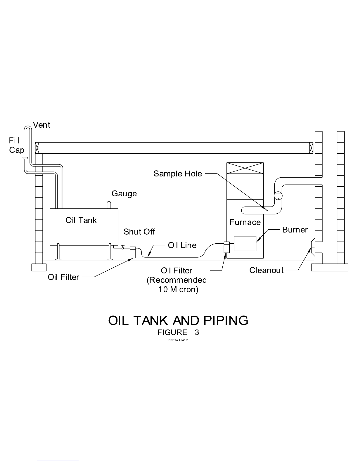
Installation, Operation and
Maintenance Manual
INSTALLATIONS MUST MEET ALL LOCAL AND FEDERAL
CODES THAT MAY DIFFER FROM THIS MANUAL
Please read this complete manual before beginning installation. These instructions must be
kept with the furnace for future reference.
CERTIFIED TO: CAN/CSA Std. B140.0 & Std. B140.4
CONFORMS TO: UL 727
GRANBY FURNACES INC.
PO Box 637
12118 Hwy 209
Parrsboro Nova Scotia Canada
B0M 1S0
www.GranbyIndustries.com
Page 2

SUMMIT-MULTI – INSTALLATION/OPERATION MANUAL
TABLE OF CONTENTS
1.0 Homeowner Information 3
1.1 Introduction 3
1.2 Air Filter 3
1.3 Regular Maintenance 3
1.4 Warnings 3
1.5 Direct Vent 3
1.6 Shutting Furnace Down 3
1.7 Restarting Furnace 4
2.0 Installation 4
2.1 Important 4
2.2 Caution 4
2.3 Installation Codes 4
2.4 Multi-Position 5
2.5 Placement & Venting 5
2.6 MAX/EVO AC/Auxiliary Sensor Installation 7
2.7 Assemble & Install Burner 8
2.8 Changing Nozzle 8
2.9 Set Burner for Efficient Operation 8
2.10 Classic Air Blower Settings 9
2.11 Air Conditioning 9
2.12 Humidifier 9
2.13 Thermostat Anticipator Setting 9
2.14 Fan Control 10
2.15 Off Cycle Air Circulation 10
2.16 MAX Blower Operation 11
3.0 Burner Specifications 12
4.0 Blocked Vent Switch 14
5.0 Classic Air Comfort Adjustments 15
6.0 Oil Tank & Piping 15
7.0 Blower Removal 15
8.0 General Specifications 15
9.0 Trouble Shooting Guide 17
9.1 MAX/EVO LED Indicators 18
9.2 MAX/EVO Sensor Diagnostics 19
5IM-OF-K6C0-01
Jun/11
1
Page 3

SUMMIT-MULTI – INSTALLATION/OPERATION MANUAL
10.0 Appendix
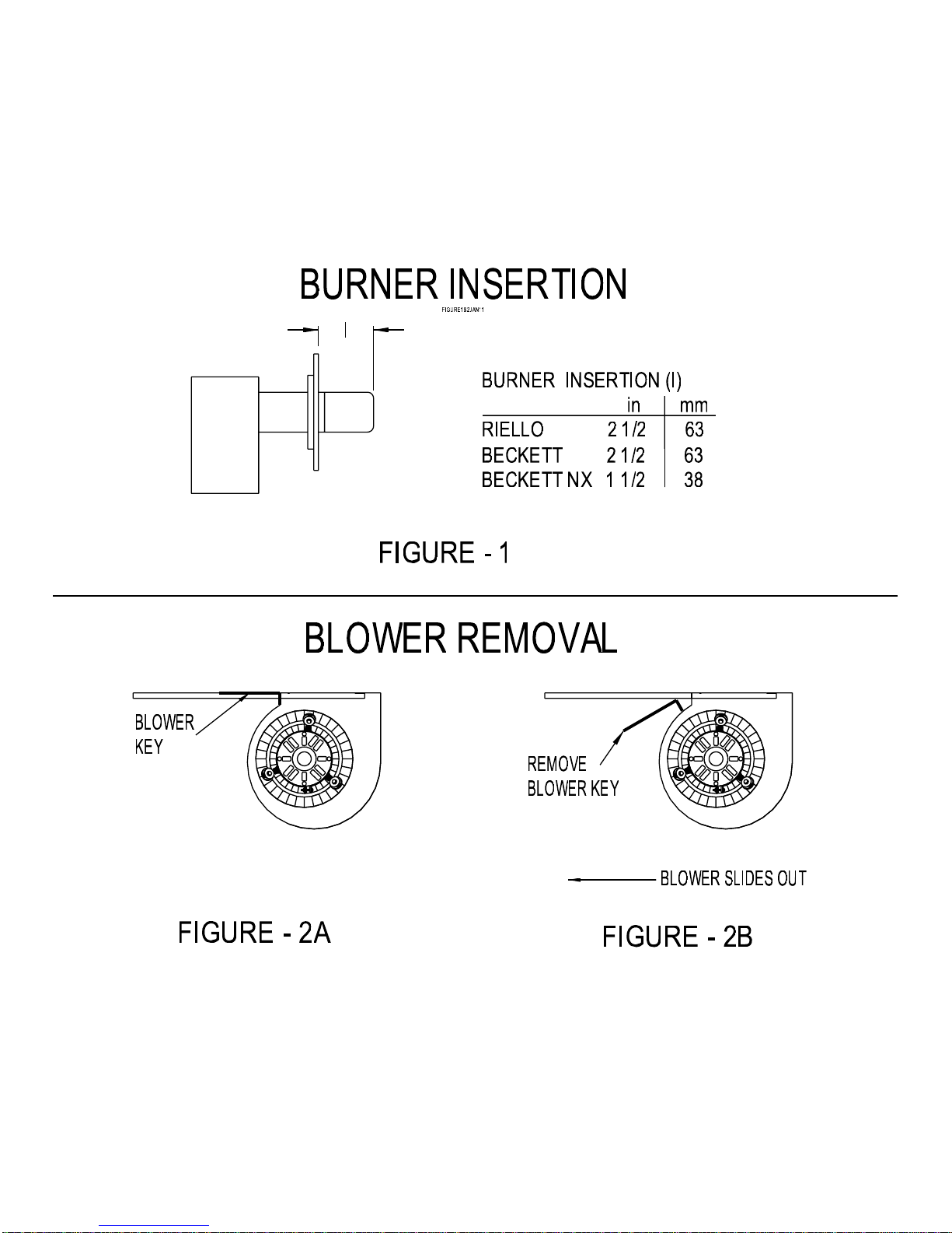
Figure – 1 Burner Insertion
Figure – 2A Blower Removal
Figure – 2B Blower Removal
Figure – 3 Oil Tank & Piping
Figure – 4 Classic Air Wiring Diagram
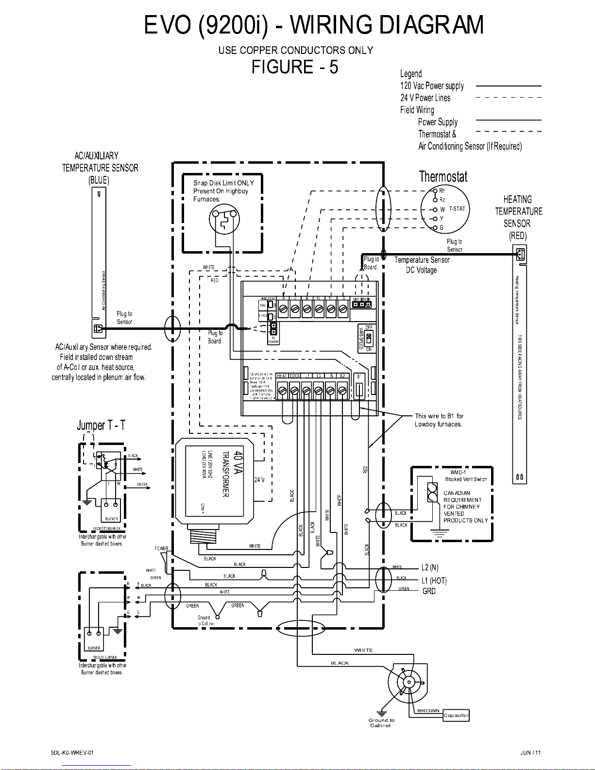
Figure – 5 EVO 9200i Wiring Diagram
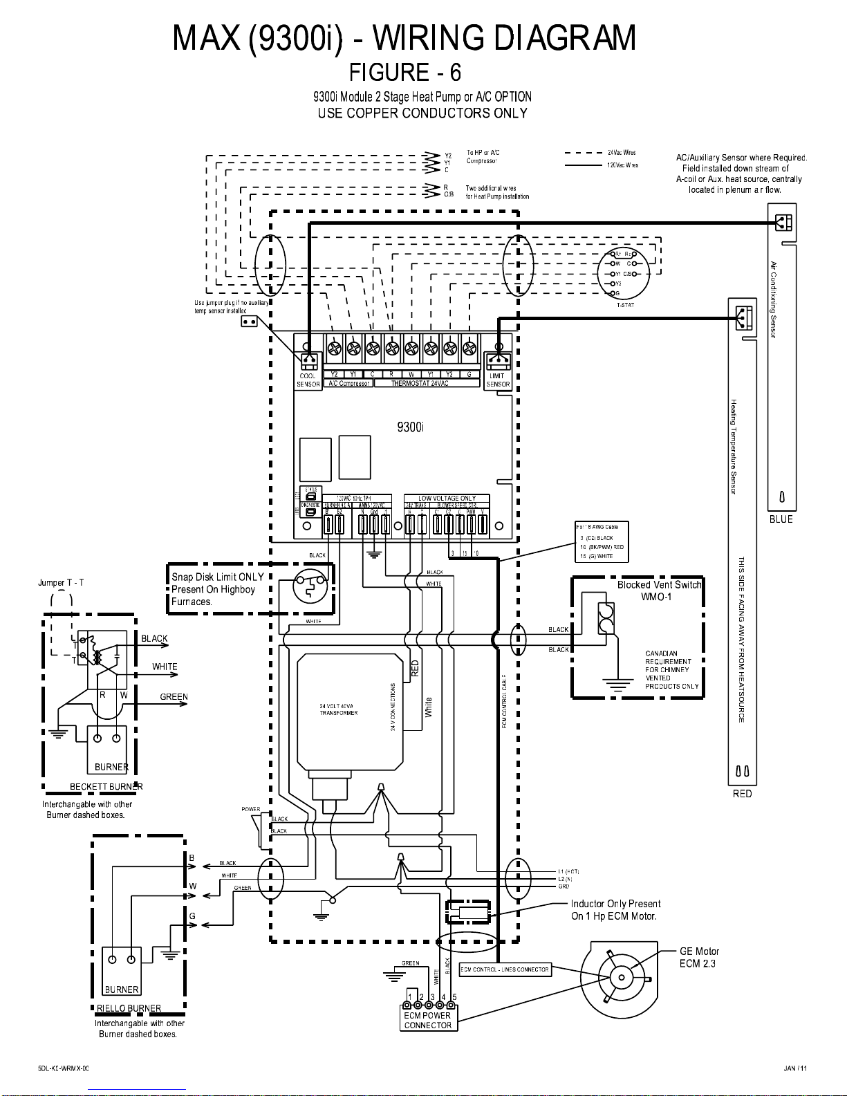
Figure – 6 MAX 9300i Wiring Diagram
Figure – 7 Sub-base Instructions
Figure – 8 Dimensions
Figure – 9 Return Air Filter Locations
Figure – 10 Fan Center Dip Switch
Figure – 11 Exploded Parts
Table – 1 Classic Air Parts List
Table – 2 EVO Parts List
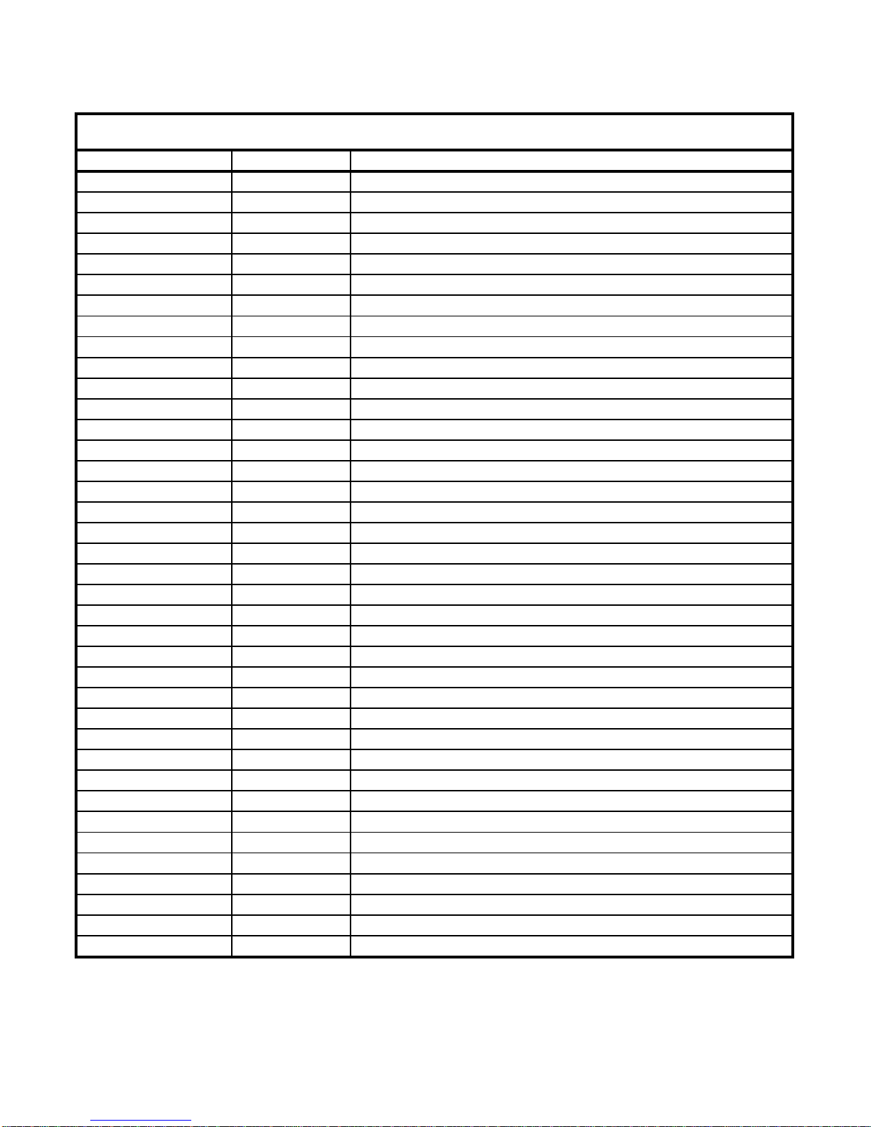
Table – 3 MAX Parts List
Keep this manual in a safe place for future reference.
Follow manual carefully for the correct way to install and operate this unit.
Do not operate this appliance until operating instructions have been read and fully understood.
SAVE THESE INSTRUCTIONS
5IM-OF-K6C0-01
Jun/11
2
Page 4

SUMMIT-MULTI – INSTALLATION/OPERATION MANUAL
1.0 HOMEOWNER INFORMATION
1.1 INTRODUCTION
Please read and understand this manual before installing, operating or maintaining the
furnace. To ensure you have a clear understanding of the operating procedures of this
appliance please take the time to read section 1.0 HOMEOWNER INFORMATION.
1.2 AIR FILTER
To maintain furnace performance and safety, replace dirty filters as required or at least once
every heating season. Use new approved disposable filters of the same size or clean
permanent filters according to manufacturer’s instructions. Replace the filter or clean the filter
more often if dusty conditions exist. Dirty, clogged or wrongly sized filters will impair the
furnace performance and may cause the furnace to shut down or overheat.
1.3 REGULAR MAINTENANCE
Have qualified technician check complete furnace operation at least once a year. In Canada
see B139, Section 14, Maintenance, for recommended servicing procedure. Heat exchanger
ducts are accessed through access panel at front of unit. Replace flue pipes if there is any
sign of corrosion or other problems. Cerafelt (1/4”) gaskets may have to be replaced.
1.4 WARNINGS
NEVER burn garbage or paper in the unit.
NEVER store combustible material around it.
DO NOT attempt to start burner when excess oil has accumulated, when unit is full of vapour
or when heat exchanger is very hot.
DO NOT use gasoline, crankcase drainings or any oil containing gasoline.
1.5 DIRECT VENT
It is the responsibility of the homeowner to ensure that the area around the Direct Vent
terminal and air intake is free of snow, ice and debris. The vent terminal should be checked
during heavy snowstorms to ensure proper operation.
1.6 SHUTTING FURNACE DOWN
POWER OFF Turn off main power switch.
FUEL OFF Shut off manual fuel supply valve.
Always keep manual fuel supply valve shut off if the burner is shut down for an extended
period of time.
5IM-OF-K6C0-01
Jun/11
3
Page 5

SUMMIT-MULTI – INSTALLATION/OPERATION MANUAL
1.7 RESTARTING FURNACE
Follow this procedure before restarting a unit that has been shut down for an extended period
of time:
INSPECTION Have the furnace/system serviced and inspected by a qualified technician.
FUEL Turn on fuel supply and check that there are no leaks.
POWER Turn on power and check that the furnace starts and operates as usual.
OPERATION If the furnace/system fails to operate or operates in an unusual manner, call
your service technician. If the burner fails to operate at any time, call a
qualified burner technician.
2.0 INSTALLATION
2.1 IMPORTANT
Read these instructions thoroughly before installing furnace or starting burner. Consult local
authorities about your local Fire Safety Regulations. All installations must be in accordance
with local state or provincial codes. Improper installation will result in voiding of warranty.
2.2 CAUTION
DO NOT START THE BURNER UNTIL ALL FITTINGS, COVERS AND DOORS ARE IN
PLACE. DO NOT TAMPER WITH THE FURNACE OR CONTROLS, CALL A QUALIFIED
BURNER TECHNICIAN. FOR YOUR SAFETY: DO NOT STORE OR USE GASOLINE O R
OTHER FLAMMABLE VAPORS AND LIQUID IN THE VICINITY OF THIS OR ANY OTHER
APPLIANCE.
2.3 INSTALLATION CODES
INSTALLATION MUST COMPLY WITH THE REQUIREMENTS OF AUTHORITIES HAVING
JURISDICTION. All local and national codes governing the installation of oil burning
equipment, wiring and venting must be followed. Some of the applicable codes are:
CAN/CSA B139 Installation Code for Oil Burning Equipment
NFPA 31 Installation Code for Oil Burning Equipment
ANSI/NFPA 90B Warm Air Heating and Air Conditioning Systems
ANSI/NFPA 70 National Electrical Code
CSA C22.1 Canadian Electrical Code
ANSI/NFPA 211 Chimneys, Fireplaces, Vents and Solid Fuel Burning Appliances
The latest versions of the above codes, which have been approved for use in the location of
the installation, must be used.
5IM-OF-K6C0-01
Jun/11
4
Page 6

SUMMIT-MULTI – INSTALLATION/OPERATION MANUAL
2.4 MULTI – POSITION
The Summit-multi is designed to operate in the conventional uplfow mode, in horizontal mode
or as a downflow furnace. The breech is convertible from front to rear by switching the breech
pipe and cover plates. The burner is always installed in an upright position by four (4) nuts.
2.5 PLACEMENT & VENTING
Furnace installation shall conform to the required installation code for oil-fired equipment (USA:
NFPA 31, Canada: CSA B139).
UPFLOW If required, support furnace on a Granby Appliance Stand or four (4)
concrete blocks. Make sure each corner of furnace base is supported.
For a furnace installed on a combustible floor, ensure that the
requirements of the authorities having jurisdiction are satisfied. Floor must
be strong enough to carry the weight of the furnace. The furnace is
shipped in upflow configuration.
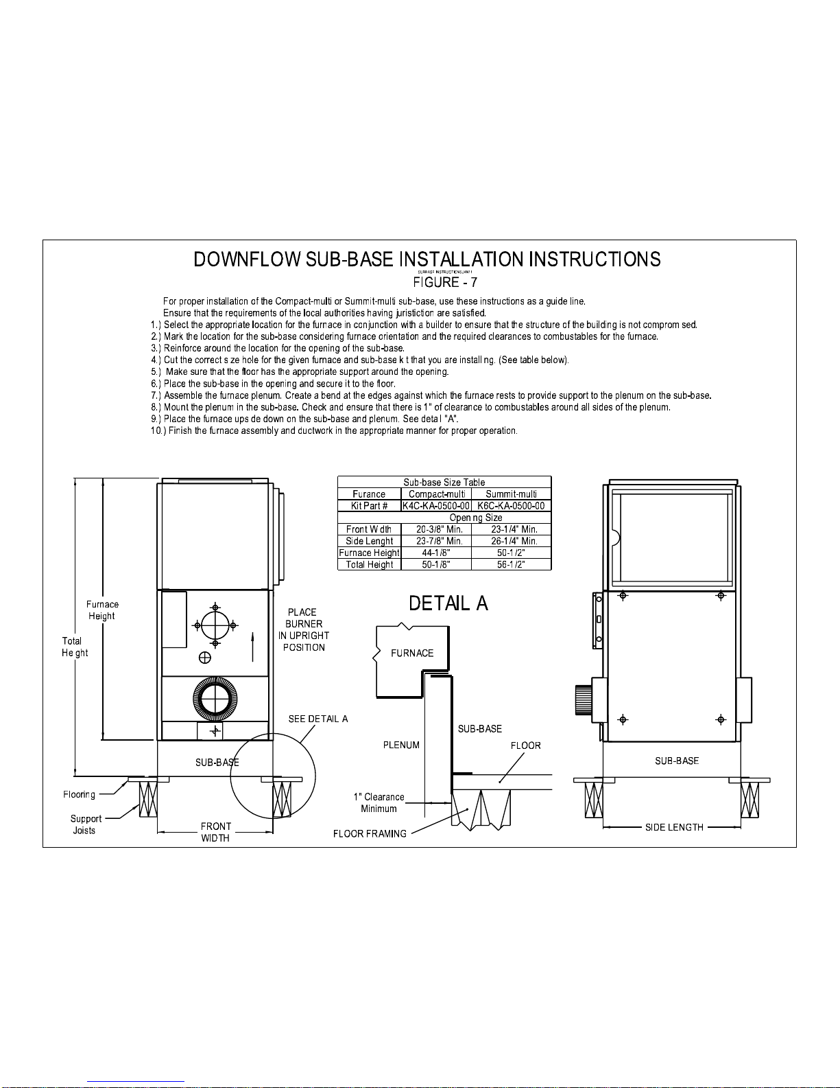
DOWNFLOW Install the plenum and sub-base as shown in the illustration (included with
sub-base kit K6C-KA-0500-00). For furnaces installed on a combustible
floor, ensure that the requirements of the authorities having jurisdiction are
satisfied. The floor must be strong enough to carry the weight of the
furnace. A sub-base is required to support the furnace, maintains the
clearances to combustible materials through the floor and provides a
convenient attachment to the plenum. Refer to Figure – 7.
HORIZONTAL In suspended horizontal positions use the eyebolts provided in kit (K4C-
KA-0200-00). For installations where the furnace will be supported from
below, use 4” long 3/8” UNC bolts as adjustable legs. Four weld nuts (3/8
- 16 UNC) are concealed behind knockouts on either side of the furnace.
Determine the appropriate side and remove the knockouts. Eyebolts
complete with locking nuts are available. The locking nuts should be
threaded on the eyebolt 3/4” to 1”. This provides a stop for the eyebolt.
CLEARANCES Before placing unit, review installations clearances as shown on the
furnace operating decal and in section 7.0 GENERAL SPECIFICATIONS.
LOCATION Install the furnace clos e to chimney or vent and central to ductwork.
BREECH Move the breech pipe to the rear if rear breech is required.
CHIMNEY/VENT Connect the furnace to a chimney/vent system of size and condition
required by the installation code. Furnace is approved for factory built
chimney type “L” vents. See the furnace operating decal for approved
vent/flue pipe sizes. Maximum flue gas temperature is 575°F.
WALL VENTING Furnace is approved for Granby Direct Vent with Riello burner.
5IM-OF-K6C0-01
Jun/11
5
Page 7

SUMMIT-MULTI – INSTALLATION/OPERATION MANUAL
COMBUSTION & Install openings and ductwork to the furnace room to provide fresh outside
VENTILATION AIR combustion and circulation air for cooling the furnace casing, as
installation code requires (USA NFPA 31, Canada CSA B139). If installed
in a closed room, provide two free air ventilation openings of at least 8” x
12” (96 sq. in.) free flow area near ceiling and floor. Oil burners must have
sufficient air to allow vent systems to operate properly. See the furnace
operating label. This is not applicable to Direct Vent installations.
ELECTRICAL Wire according to the National Electrical Code (Canadian Electrical Code
in Canada) or local codes. Use a separately fused #12 electrical line
directly from the service panel to the furnace junction box. Install a
manual shut-off switch at the door or stairway to furnace room so furnace
can be shut off remotely.
VENT PIPE See NFPA 31 (USA) or CSA B139 (Canada) code. Breech is certified for
5” vent pipe. Keep vent/flue pipe as short as possible with min. 1/4” per
foot upward slope. Use approved fitting through a wall. Vent/flue pipes
MUST NOT pass through a ceiling.
BREECH The breech is convertible from front to rear by switching the breech pipe
and cover panels.
DRAFT Use approved control supplied for 5” pipe. Use two draft controls on strong
CONTROL draft chimneys. Set specified draft pressure to -0.03” wc. The above is
not applicable to Direct Vent installations.
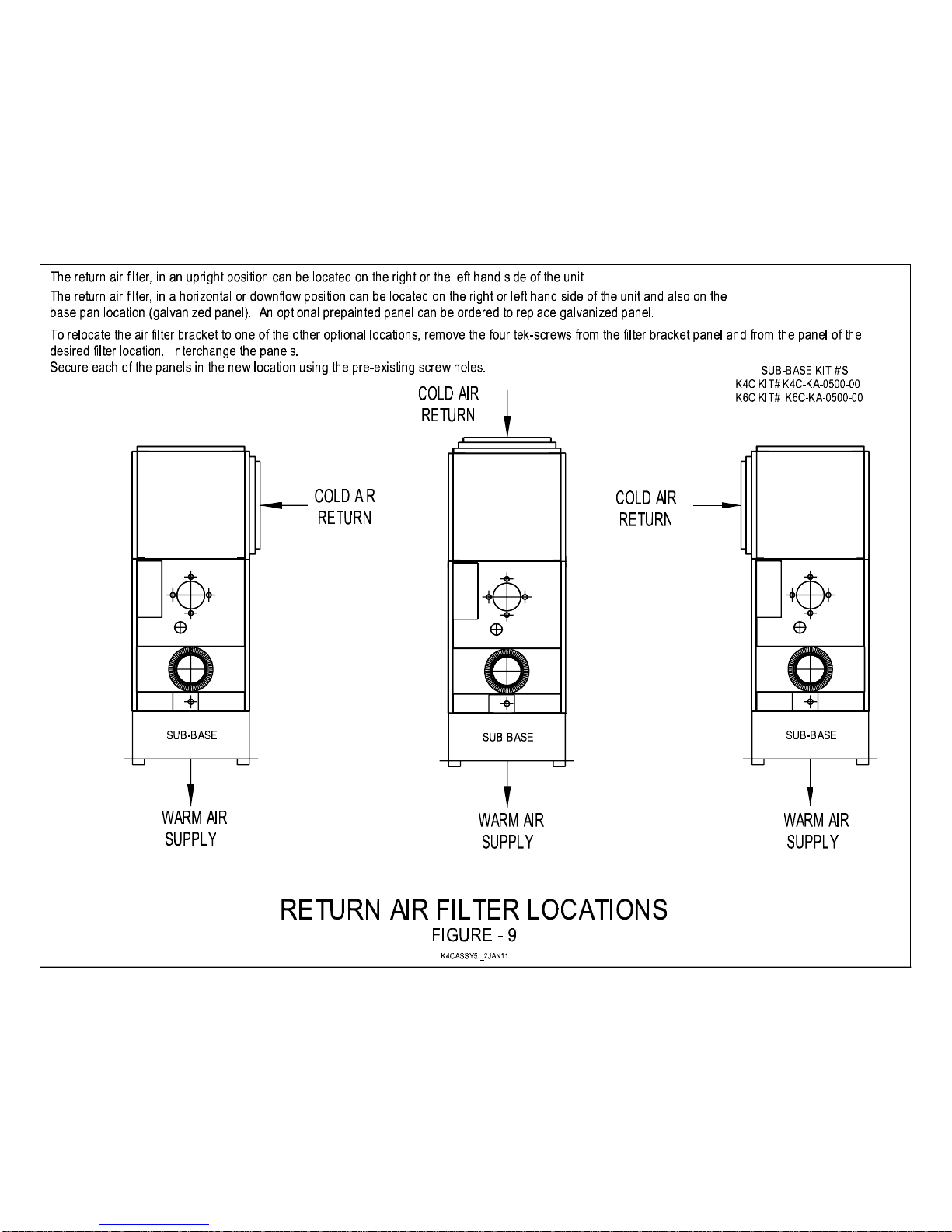
FILTER The filter bracket can be moved from the left side to the right side or the
LOCATION bottom of the furnace. Refer to Figure – 9.
ADD-ON Any furnace can only have one additional appliance added to the
ductwork. Other items which do not drastically reduce the air flow are
allowed.
5IM-OF-K6C0-01
Jun/11
6
Page 8

SUMMIT-MULTI – INSTALLATION/OPERATION MANUAL
2.6 MAX/EVO AC/AUXILIARY SENSOR INSTALLATION
Mandatory for MAX series furnaces when equipped with an A/C coil. Optional for EVO series
furnaces when equipped with an A/C coil, defaults to full speed on A/C if not installed.
AC/Auxiliary sensor kit contents:
AC/Auxiliary sensor mounted in sensor box with 86” of sensor cable.
Three (3) mounting screws.
Four (4) cable clamps and clamp screws
Mounting the AC/auxiliary sensor
a) Disconnect the POWER from the furnace.
b) Find a location in the plenum down-stream of the air conditioning coil or auxiliary heating
unit to mount the AC/auxiliary temperature sensor. This location should be centrally
located in the air stream of the plenum and far enough from the A/C coil or heat source, so
that the auxiliary sensor senses an even temperature from the coil. The AC/Auxiliary
sensor should not be more than 12” downstream from an “A” coil. The sensor should be
located as high up the supply plenum as possible. The minimum height of 10” above the
cabinet and centrally on the side of the plenum. Also make sure that the cable from the
AC/auxiliary sensor will reach back to the wiring channel on the furnace and that the
cable can be routed to avoid contact with any extremely hot surfaces (i.e. flue pipe).
c) In the plenum location chosen, drill a 7/8” hole or construct a hole large enough to insert
the AC/auxiliary sensor into the plenum. The sensor probe should not touch the plenum
metal when the box is mounted to the plenum.
d) Remove the cover from the sensor box. Using the three screws provided, mount the
sensor box to the plenum through the three pilot holes in the sensor box. IMPORTANT:
Ensure that the SENSOR ORIENTATION is correct with the AIRFLOW arrow. See sensor
mount in sensor box.
e) Place the cover back on the sensor box.
f) Remove the cover from the wiring channel on the furnace.
g) Locate the 5/8” hole with the black plug on the wiring channel and remove the plug (plug
can be discarded).
h) Fit the end of the sensor cable through the 5/8” hole and make the cable connection to the
auxiliary sensor female plug on the circuit board (note plug release tab orientation).
i) Press the strain relief bushing on the auxiliary sensor cable in to the 5/8” hole.
j) Replace the wiring channel cover.
k) Reconnect the power to the system, this resets the circuit board to recognize that the
sensor is connected. Test the system.
With the AC/auxiliary sensor properly connected, on a call for air conditioning there is a 15
second time delay for the blower to come on slowly and the blower speed will modulate
according to the plenum temperature.
5IM-OF-K6C0-01
Jun/11
7
Page 9

SUMMIT-MULTI – INSTALLATION/OPERATION MANUAL
2.7 ASSEMBLE & INSTALL BURNER
ASSEMBLE Check burner model is correct for furnace rating required. Assemble as
per burner manufacturer’s instructions.
SET END CONE Beckett AFG - see manufacturer’s instructions. Riello - Set turbulator as
per furnace operating decal.
SELECT NOZZLE Select oil input, nozzle required and burner configuration as shown on
furnace operating decal.
INSTALL NOZZLE Install nozzle, check for clean seating and tighten nozzle adaptor.
ELECTRODES See burner manufacturer’s instructions for correct setting.
INSERTION See Figure – 1 and section 7.0 GENERAL SPECIFICATIONS.
MOUNT BURNER Tighten top nut first so burner tips down slightly. The burner is always
installed in an upright position by four (4) nuts.
PUMP BY- PASS For one pipe system; use a factory setting (no plug).
PLUG
WIRING Refer to Figure – 4, 5 or 6 for correct burner connections.
THERMOSTAT Connect thermostat terminals.
2.8 CHANGING NOZZLE
NOZZLE CHANGE If a new nozzle of a different size is installed, change the heating blower
speed according to the operating decal or section 3.0 BURNER
SPECIFICATIONS. Applicable to Classic Air units only.
2.9 SET BURNER FOR EFFICIENT OPERATION
SET END CONE Beckett MB air tube with L1 head – see burner manual. Riello set
turbulator using furnace operating decal.
PUMP PRESSURE Refer to section 3.0 BURNER SPECIFICATIONS or operating decal.
BURNER AIR Refer to section 3.0 BURNER SPECIFICATIONS or operating decal.
SAMPLING HOLE On smoke/vent pipe, between appliance breech and draft control, punch
or drill a 1/4” round opening. Not applicable to Direct Vent.
DRAFT PRESSURE Using an accurate draft meter; adjust the draft control to obtain -0.03” wc
draft pressure at the breech-sampling hole. Use two barometrics if
necessary. Not applicable to Direct Vent.
BURNER SETTING After 15 minutes of normal operation, check SMOKE for zero to trace
reading and measure CO
. Re adjust the burner controls as required.
2
5IM-OF-K6C0-01
Jun/11
8
Page 10

SUMMIT-MULTI – INSTALLATION/OPERATION MANUAL
EFFICIENCY Always leave burner set with CO2 reading about 1% lower than the peak CO2
efficiency achieved with a zero to trace smoke (e.g. a zero to trace reading of
12.5% CO2 should be set back 1% to 11.5%). This gives better allowance for
fuel and draft variations and maintains a better seasonal efficiency. When the
burner is set, lock the adjustments with locking nuts. Always set flame with
proper draft, smoke and CO2 measurements.
DO NOT START BURNER UNTIL ALL FITTINGS AND COVERS ARE IN PLACE.
2.10 CLASSIC AIR BLOWER SETTINGS
Ensure power is off when adjusting blower setting. For heating, use the blower speeds
shown on the furnace specifications to give a rise of 70 - 85°F. The #4 Lo blower speed can
be used for air circulation when either heating or cooling are not required. Set blower speeds
to match the installation requirements.
2.11 AIR CONDITIONING
IMPORTANT – MAX/EVO models that make use of the Auxiliary Sensor for better
dehumidification MUST have a Thermal Expansion (TX) Valve incorporated into the A/C piping
system. Most evaporator manufacturers have the option of supplying the thermal expansion
valve built right in to the evaporator. If there is not a thermal expansion valve on the
evaporator then a thermal expansion valve kit MUST be properly installed in the evaporator
system to ensure proper operation of the A/C system. The firing rate of 157,000 Btu/h, on the
Classic Air, EVO or MAX, cannot be used in conjunction with an air conditioning coil.
2.12 HUMIDIFIER
If a humidifier is installed ensure that no water can drip or run from it into the furnace. This
would cause deterioration and void the furnace warranty.
2.13 THERMOSTAT ANTICIPATOR SETTING
The thermostat anticipator setting is only applicable to the non-electronic type of thermostat.
Electronic thermostats do not have an anticipator setting. All Classic Air burners use 0.2
amps. The MAX/EVO control requires 0.1 amps as a thermostat anticipator setting. Check
that the thermostat anticipator setting matches the primary control circuit current draw. This
setting affects the thermostat’s response to the control.
5IM-OF-K6C0-01
Jun/11
9
Page 11

SUMMIT-MULTI – INSTALLATION/OPERATION MANUAL
2.14 FAN CONTROL
CLASSIC AIR
Limit 165°F - Factory set.
Fan On 45 seconds after burner starts
Fan Off Adjustable on electronic board
MAX/EVO
Standard Mode EVO Only
High Limit 180°F (Resets at 120°F)
Fan On (Heat) 130°F
Fan Off (Heat) 90°F
Fan On (Cool) 15-second delay
Fan Off (Cool) 45-second delay
Variable Speed Mode
High Limit 180°F (Resets at 120°F)
Fan On (Heat) Varies to maintain 145°F
Fan Off (Heat) 90°F
Fan On (Cool) *Varies to maintain 48°F with Auxiliary Sensor installed
Fan Off (Cool) 65°F
*If no Auxiliary Sensor is installed then the cooling cycle will act as in the standard mode.
2.15 OFF CYCLE AIR CIRCULATION
#4 LO SPEED All Classic Air furnace models have the #4 Lo speed switch for optional
constant off cycle air circulation. Switch is located on furnace wiring box.
“FAN ON” When “FAN ON” is selected on the thermostat of a Classic Air furnace, the
blower will run constantly at the #1 Hi speed providing heat, cooling or neither
as selected.
EVO/MAX Air circulation can be operated from the thermostat. Blower will run on low
speed.
5IM-OF-K6C0-01
Jun/11
10
Page 12
SUMMIT-MULTI – INSTALLATION/OPERATION MANUAL
2.16 MAX BLOWER OPERATION
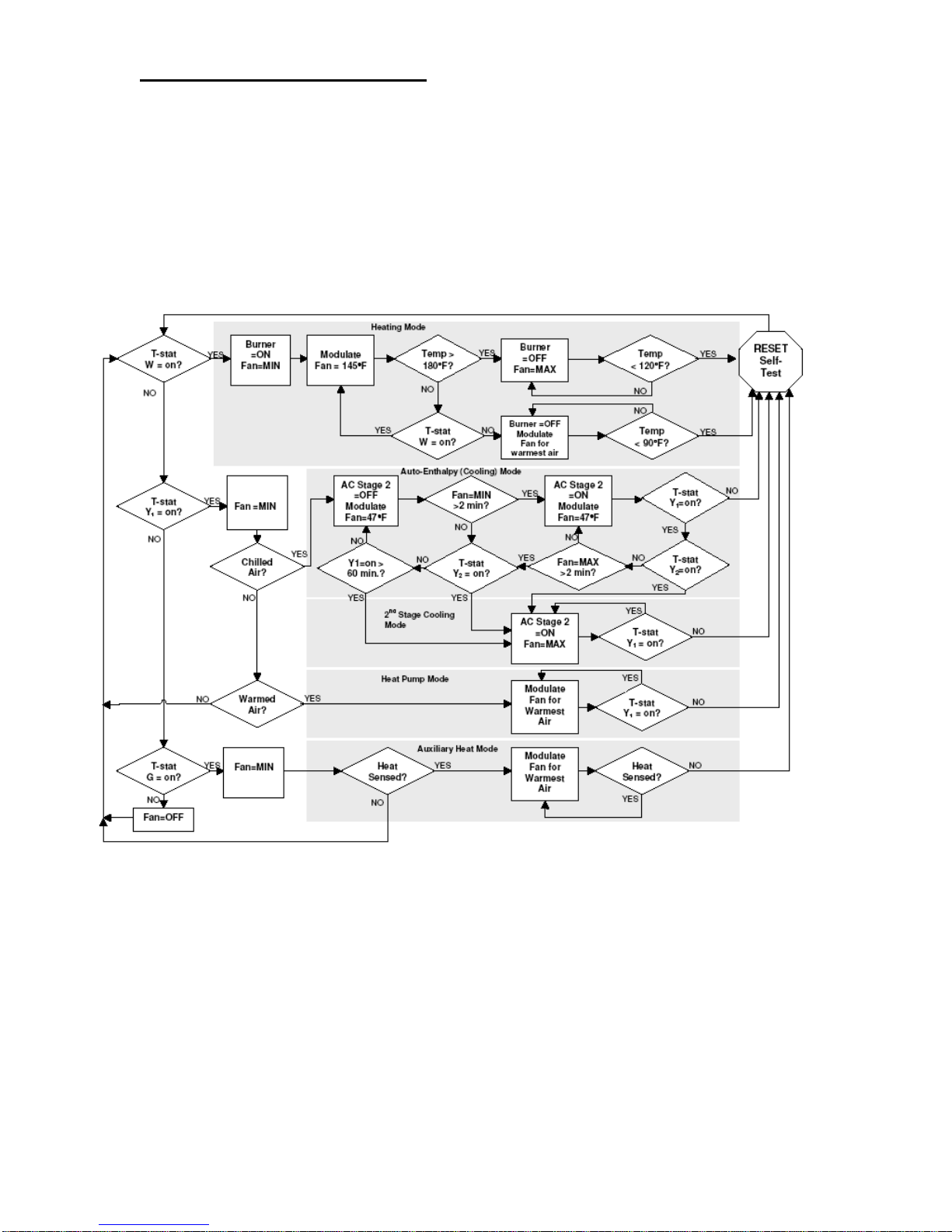
The MAX furnace has an advanced control that performs all of the safety and control functions.
There are two temperature sensors. One comes installed in the furnace and the AC/auxiliary
temperature sensor is installed after the A coil or auxiliary heating device. The control will
automatically handle two stage air conditioning and auxiliary heat such as electric plenum
heaters or heat pumps. The control will automatically modulate the blower for optimal airflow
regardless of the mode of operation. In heating mode the blower will modulate to maintain a
constant plenum temperature. In cooling mode the blower will modulate to attain the best
dehumidification performance even with two stage compressors. The control logic is detailed
below.
5IM-OF-K6C0-01
Jun/11
11
Page 13
SUMMIT-MULTI – INSTALLATION/OPERATION MANUAL
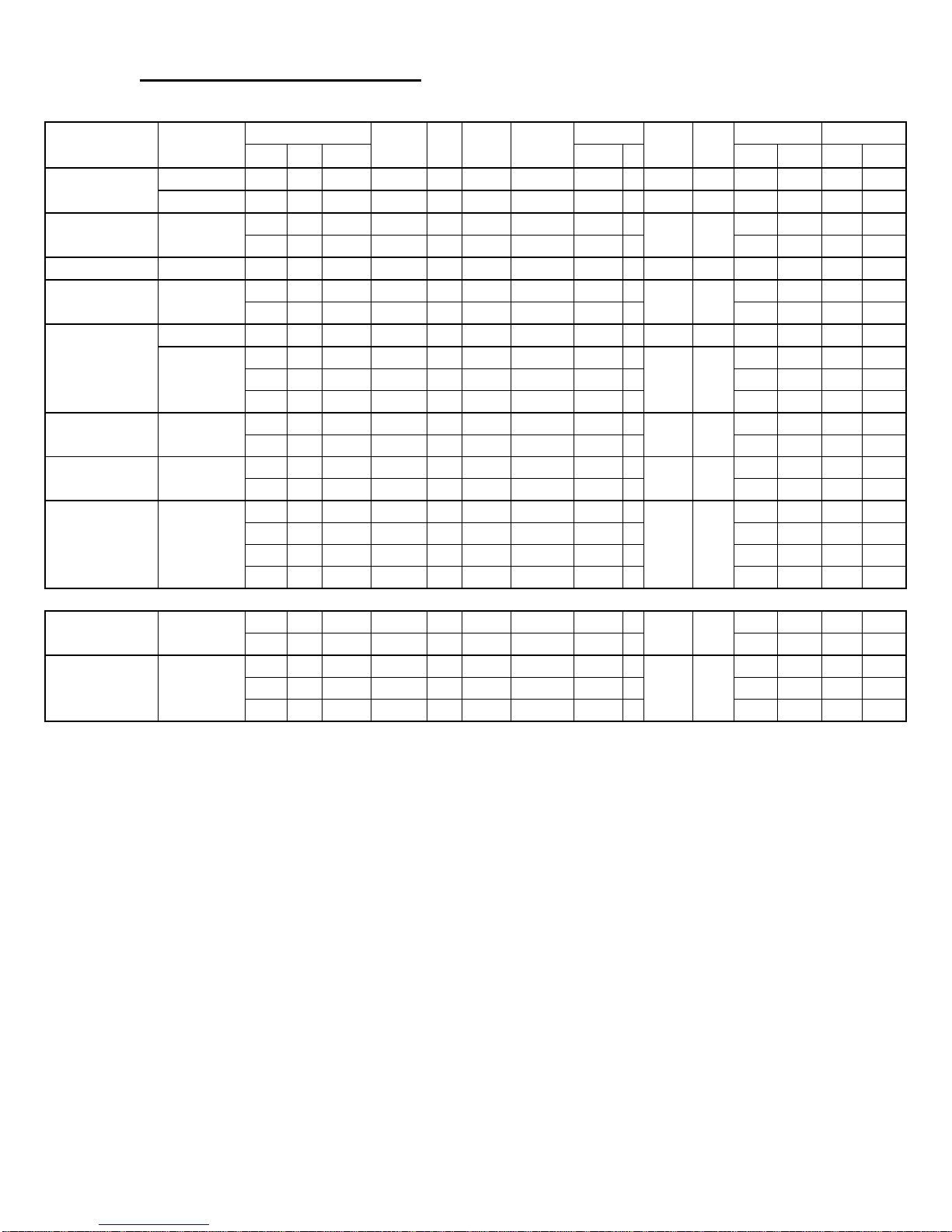
3.0 BURNER SPECIFICATIONS
CLASSIC AIR
Model Burner
K6C-G2-K120-03
K6C-N2-K125-03 Beckett NX-LC
K6C-E1-K110-03 Riello 40 F3 0.92 3.48 128,800 0.75 60W 150 5.0 3.0 107,000 31 GT 10-10 1/2 hp 1300 1250 2 1
K6C-E3-K120-03 Riello 40 F5
K6C-G3-K163-05
K6C-N2-K129-05 Beckett NX-LH
K6C-N3-K164-05 Beckett NX-LB
K6C-E3-K160-05 Riello 40 F5
Direct Vent / Evacuation directe
K6C-V3-K120-03 Riello 40 BF5
K6C-V3-K145-05 Riello 40 BF5
Beckett AFG F3 0.92 0.00 128,800 0.75 70B 150 6/0 - 109,000 32 GT 10-10 1/2 hp 1300 1250 2 1
Beckett AFG F6 1.00 0.00 140,000 0.85 70B 140 5/1 - 120,000 35 GT 10-10 1/2 hp 1300 1250 2 1
Beckett AFG F3 0.90 3.40 126,000 0.75 70B 150 0/10 - 109,000 32 GT 12-10 3/4 hp 1550 1475 3 2
Beckett AFG F6
USGPH L/h Btu/h (psi) Btu/h Kw (inches) (hp) 0.2”wc 0.5”wc 0.2”wc 0.5”wc
Input
0.92 3.47 128,800 0.75 60A 150 2.2 - 112,000 33
1.03 3.88 144,200 0.85 60A 150 3.0 - 125,000 37 1300 1250 2 1
0.92 3.48 128,800 0.75 60W 150 3.2 1.0 107,000 31
1.04 3.94 145,600 0.85 60W 150 3.4 2.0 122,000 36 1300 1250 2 1
1.02 3.85 142,800 0.85 70B 150 0.5/5 - 122,000 36
1.22 4.64 170,800 1.00 70B 150 1/5 - 143,000 42 1550 1475 3 2
1.35 5.10 189,000 1.20 70B 130 1/7 - 163,000 48 1700 1600 1 1
0.94 3.55 131,600 0.75 60A 160 2.2 - 115,000 34
1.06 4.00 148,400 0.85 60A 155 3.7 - 129,000 38 1550 1475 3 2
1.22 4.64 170,800 1.00 60B 150 2.5 - 149,000 44
1.35 5.10 189,000 1.10 60B 150 4.0 - 164,000 48 1700 1600 1 1
0.92 3.48 128,800 0.75 60W 150 3.2 1.0 107,000 31
1.04 3.94 145,600 0.85 60W 150 3.3 2.0 122,000 36 1550 1475 3 2
1.22 4.64 170,800 1.00 60W 150 3.4 2.5 143,000 42 1550 1475 3 2
1.35 5.10 189,000 1.10 60W 150 4.0 3.5 157,000 46 1700 1600 2 1
0.92 3.48 128,800 0.75 70B 150 4.5 1.5 107,000 31
1.04 3.94 145,600 0.85 60W 150 5.0 2.0 122,000 36 1300 1250 2 1
0.92 3.48 128,800 0.75 70B 150 4.5 1.5 107,000 31
1.04 3.94 145,600 0.85 60W 150 5.0 2.0 122,000 36 1550 1475 2 1
1.22 4.64 170,800 1.00 60W 150 6.2 2.5 143,000 42 1550 1475 2 1
Nozzle
Pump
Air
Setting
Turbulator
Output Blower Motor Heating cfm@ Blower Speed
GT 10-10 1/2 hp
GT 10-10 1/2 hp
GT 12-10 3/4 hp
GT 12-10 3/4 hp
GT 12-10 3/4 hp
GT 10-10 1/2 hp
GT 12-10 3/4 hp
1300 1250 2 1
1300 1250 2 1
1550 1475 3 2
1550 1475 3 2
1550 1475 3 2
1550 1475 3 2
1300 1250 2 1
1550 1475 2 1
5IM-OF-K6C0-01
Jun/11
12
Page 14
SUMMIT-MULTI – INSTALLATION/OPERATION MANUAL
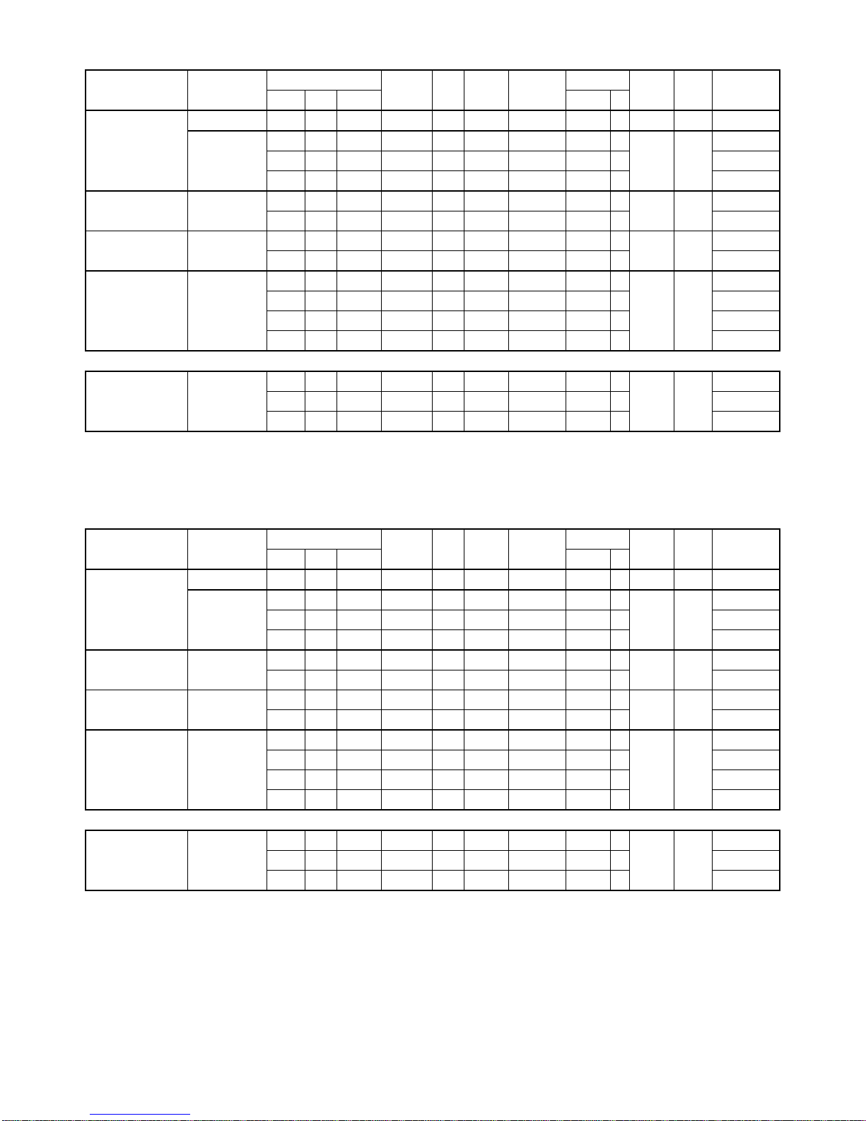
EVO
Model Burner
Beckett AFG F3 0.90 3.40 126,000 0.75 70B 150 0/10 - 109,000 32 GT 12-10 3/4 hp 1210*
K6C-G2-K163-F5
K6C-N2-K129-F5 Beckett NX-LH
K6C-N3-K164-F5 Beckett NX-LB
K6C-E3-K160-F5 Riello 40 F5
Direct Vent / Evacuation directe
K6C-V3-K145-F5 Riello 40 BF5**
Beckett AFG F6
USGPH L/h Btu/h (psi) Btu/h Kw (inches) (hp)
Input
1.02 3.85 142,800 0.85 70B 150 0.5/5 - 122,000 36
1.22 4.64 170,800 1.00 70B 150 1/5 - 143,000 42 1590*
1.35 5.10 189,000 1.20 70B 130 1/7 - 163,000 48 1810*
0.94 3.55 131,600 0.75 60A 160 2.2 - 115,000 34
1.06 4.00 148,400 0.85 60A 155 3.7 - 129,000 38 1440*
1.22 4.64 170,800 1.00 60B 150 2.5 - 149,000 44
1.35 5.10 189,000 1.10 60B 150 4.0 - 164,000 48 1820*
0.92 3.48 128,800 0.75 60W 150 3.2 1.0 107,000 31
1.04 3.94 145,600 0.85 60W 150 3.3 2.0 122,000 36 1355*
1.22 4.64 170,800 1.00 60W 150 3.4 2.5 143,000 42 1590*
1.35 5.10 189,000 1.10 60W 150 4.0 3.5 157,000 46 1740*
0.92 3.48 128,800 0.75 70B 150 4.5 1.5 107,000 31
1.04 3.94 145,600 0.85 60W 150 5.0 2.0 122,000 36 1355*
1.22 4.64 170,800 1.00 60W 150 6.2 2.5 143,000 42 1590*
Nozzle
Pump
Air
Setting
Turbulator
Output Blower Motor
GT 12-10 3/4 hp
GT 12-10 3/4 hp
GT 12-10 3/4 hp
GT 12-10 3/4 hp
GT 12-10 3/4 hp
Heating CFM
1360*
1280*
1660*
1190*
1190*
* Approximately 90 Btu/h CFM
**Cannot be used in conjunction with an air conditioning coil or any device that will increase
the static pressure.
MAX
Model Burner
Beckett AFT F3 0.90 3.40 126,000 0.75 70B 150 0/10 - 109,000 32 GT 12-10 3/4 hp 1210*
K6C-G2-K163-E5
K6C-N2-K129-E5 Beckett NX-LH
K6C-N3-K164-E5 Beckett NX-LB
K6C-E3-K160-E5 Riello 40 F5
Direct Vent / Evacuation directe
K6C-V3-K145-E5 Riello 40 BF5**
Beckett AFG F6
USGPH L/h Btu/h (psi) Btu/h Kw (inches) (hp)
Input
1.02 3.85 142,800 0.85 70B 150 0.5/5 - 122,000 36
1.22 4.64 170,800 1.00 70B 150 1/5 - 143,000 42 1590*
1.35 5.10 189,000 1.20 70B 130 1/7 - 163,000 48 1810*
0.94 3.55 131,600 0.75 60A 160 2.2 - 115,000 34
1.06 4.00 148,400 0.85 60A 155 3.7 - 129,000 38 1440*
1.22 4.64 170,800 1.00 60B 150 2.5 - 149,000 44
1.35 5.10 189,000 1.10 60B 150 4.0 - 164,000 48 1820*
0.92 3.48 128,800 0.75 60W 150 3.2 1.0 107,000 31
1.04 3.94 145,600 0.85 60W 150 3.3 2.0 122,000 36 1355
1.22 4.64 170,800 1.00 60W 150 3.4 2.5 143,000 42 1590
1.35 5.10 189,000 1.10 60W 150 4.0 3.5 157,000 46 1740*
0.92 3.48 128,800 0.75 70B 150 4.5 1.5 107,000 31
1.04 3.94 145,600 0.85 60W 150 5.0 2.0 122,000 36 1355*
1.22 4.64 170,800 1.00 60W 150 6.2 2.5 143,000 42 1590*
Nozzle
Pump
Air
Setting
Turbulator
Output Blower Motor
GT 12-10 3/4 hp
GT 12-10 3/4 hp
GT 12-10 3/4 hp
GT 1 2-
GT 12-10 1 hp
10
1 hp
Heating CFM
1360*
1280*
1660*
1190*
1190*
* Approximately 90 Btu/h CFM
**Cannot be used in conjunction with an air conditioning coil or any device that will increase
the static pressure.
Note: The turbulator & air settings found in this section should be used as a guide.
5IM-OF-K6C0-01
Jun/11
13
Page 15

SUMMIT-MULTI – INSTALLATION/OPERATION MANUAL
4.0 BLOCKED VENT SWITCH
Oil-fired appliances installed in Canada require a blocked vent shut-off system when installed
on a chimney. A safety switch is included with the furnace to perform this function. It is the
installer’s responsibility to install the switch in accordance with the instructions provided. Not
applicable for Direct Vent or Power Vent systems.
Field Controls Model: WMO-1 (Manual Reset)
Switch Operation
Blocked vent switches are flue gas safety devices for detecting spillage of flue gases due to a
blocked flue or inadequate draft. After detecting a problem, the switch de-energizes the
system’s burner control.
NEVER reset the switch unless the cause of the blockage has been corrected.
Installation
1) Pierce a 5/8” hole in to the flue vent pipe near the appliance breech connection.
2) This hole must be at least 10” before the draft regulator, vertically or horizontally.
3) Remove one of the securing nuts from the threaded tube of the safety switch.
4) Tighten the other securing nut onto the pipe as far as possible.
5) Insert the threaded tube end into the pierced hole of the flue vent pipe.
6) Install the securing nut on the safety switch tube, which protrudes into the flue vent pipe.
Tighten the nut securely.
Wiring Instructions
Caution: Disconnect the electrical power when wiring the unit.
Wire the Blocked Vent Switch in accordance with The National Electrical Code and applicable
local codes. Wire the safety switch in series with the burner limit control or aquastat. Route
the wiring with an accepted wiring enclosure in accordance with the National Electrical code
and applicable local codes. Refer to wiring decal or Figure - 4, 5 or 6.
System Test Procedure
1) With the power re-established, block the chimney or vent pipe downstream of the switch.
2) Adjust the thermostat to call for heat.
3) Once the heating system has started the blocked vent switch should shut down the burner
within 10 minutes or sooner.
4) Once the system has cooled, the blocked vent switch can manually be reset.
5) This procedure should be tested a second time.
6) After testing the blocked vent switch the chimney should be cleared of obstruction and the
heating system tested on a long run cycle.
If the block vent switch shuts down the system, check to ensure there is enough draft in the
chimney and venting pipes.
5IM-OF-K6C0-01
Jun/11
14
Page 16

SUMMIT-MULTI – INSTALLATION/OPERATION MANUAL
5.0 CLASSIC AIR COMFORT ADJUSTMENTS
o Outlet air consistently too warm or too cold - change the blower motor speed to give the
specified air temperature rise (70 - 85°F).
o Outlet air gets too warm and burner shuts down - increase air by changing the blower
motor speed to give the specified temperature rise (70 - 85°F).
o Outlet air is too cold or too warm at the end of the heating cycle after the burner has
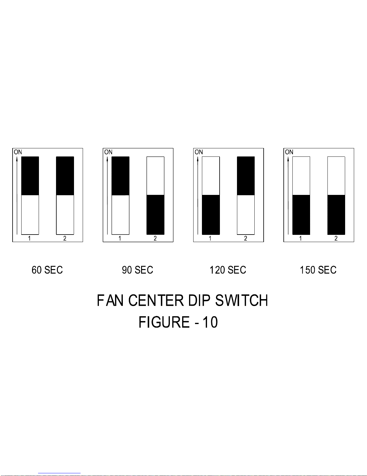
turned off - adjust the fan off dip switch on electronic fan center. See Figure – 11.
6.0 OIL TANK & PIPING
Tank installation should conform to local requirements. Install according to the applicable
code. Minimize number of connections in suction line and make all connections as tight as
possible. Use a pipe joint compound suitable for oil on all pipe threads. To reduce possibility
of air leaks, tighten stem packing gland nut on any valves installed. Check for kinks in the oil
lines as well as for possible air pockets and for loose connections. Two filters shown in Figure
- 3 are recommended. Optional tank gauge protectors and outlet protectors are available at
your local dealer.
ONE PIPE SYSTEM Where the tank is above the burner and when the oil flows by
gravity to the oil pump, a single stage fuel unit with a single oil line
to the pump may be used.
TWO PIPE SYSTEM When single line is unsuitable, use double line or see your dealer
for special oil line fittings.
7.0 BLOWER REMOVAL
Use a reversing drill with 1/4” hex drive for the sheet metal screws. Granby furnaces have a
quick release blower suspension system, which is designed to be tight and rattle free.
1. Disconnect power.
2. Remove front panel to blower compartment.
3. Remove the screw(s) from the blower key (Figure – 2A).
4. Remove the blower key and slide the blower towards the burner (Figure – 2B).
Replace the blower assembly using the reverse procedure. See Figure – 2. DO NOT start the
oil burner until installation is complete and all cleanout covers are secured in place.
8.0 GENERAL SPECIFICATIONS
CLEARANCE TO COMBUSTIBLES FOR UPFLOW & DOWNFLOW POSITIONS
Top 1” (25 mm)
Front 24” (610 mm)
Rear* 6” (51 mm)
Side** 6” (51 mm)
Side Duct 1” (25 mm)
Flue Pipe 9” (229 mm)
Floor Combustible in upflow position only
* Rear breech requires rear access of 18” (457 mm).
** Rear breech requires side access of 24” (610 mm).
5IM-OF-K6C0-01
Jun/11
15
Page 17

SUMMIT-MULTI – INSTALLATION/OPERATION MANUAL
CLEARANCE TO COMBUSTIBLES FOR HORIZONTAL POSITION
Top 6” (152 mm)
Front 24” (610 mm)
Rear* 6” (152 mm)
Side 6” (152 mm)
Side (access) 24” (610 mm)
Side Duct 1” (25 mm)
Flue Pipe 9” (229 mm)
Floor Non-Combustible
* Rear breech requires rear access of 18” (457 mm).
DRAFT PRESSURE
(not applicable to Direct Vent)
Breech draft pressure -0.03” wc
Over fire draft pressure -0.01” wc
BURNER INSERTION (overall)
Riello 2 1/2” (63 mm)
Beckett AFG 2 1/2” (63 mm)
Beckett NX 1 1/2” (38 mm)
AIR/BLOWER DATA
External static - Non A/C 0.2” wc
External static - A/C 0.5” wc
Maximum air temperature rise 85°F
High limit, max. design outlet temp. 200°F
Thermostat anticipator 0.2 amps (Classic Air)
0.1 amps (MAX/EVO)
MOTOR/BLOWER
3/4 hp 4 Speed/GT 12-10
1 hp ECM/GT12-10
FAN/HIGH LIMIT CONTROL
Classic Air Honeywell Fan Center & Thermo-Disk
EVO 9200i Control Board (Variable or Non-Variable)
MAX 9300i Control Board (Variable)
DIMENSIONS
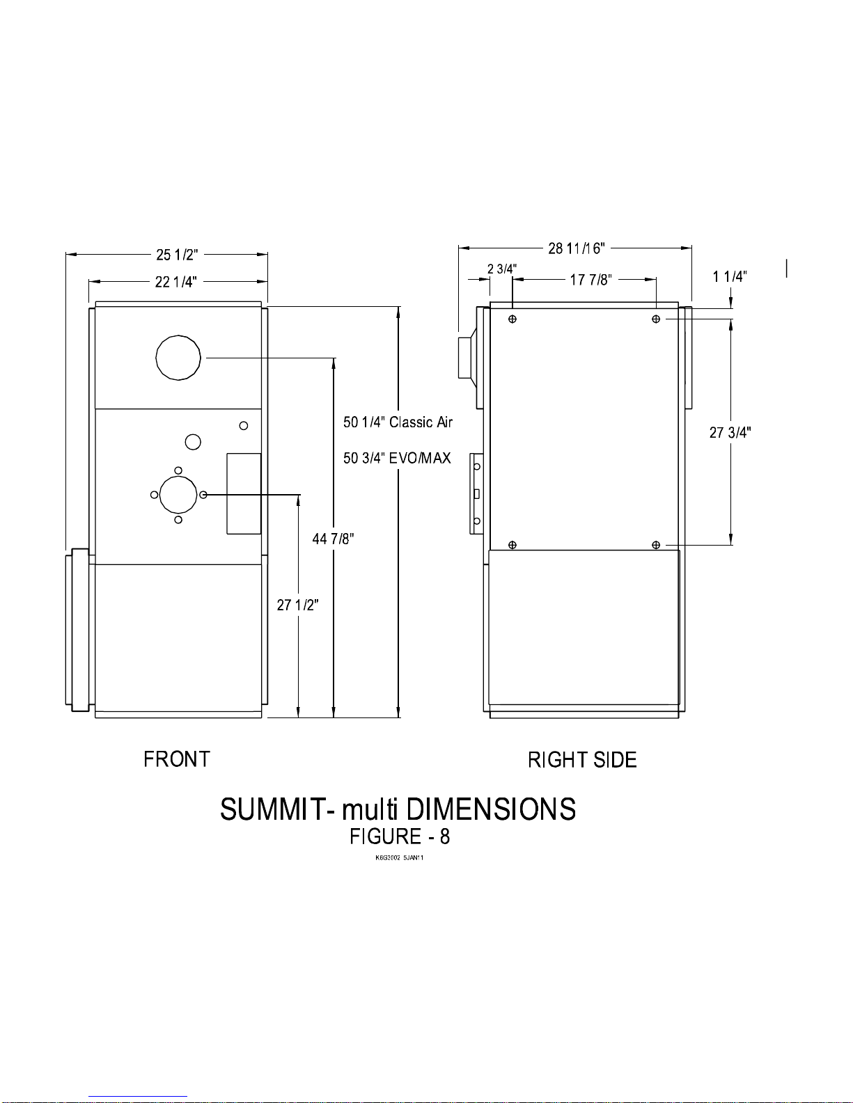
Depth 26 5/8” (676 mm)
Height 51 1/4” (1302 mm)
Width 22 5/16” (567 mm)
PLENUM DIMENSIONS (W x D)
Warm air supply 21” x 23 1/2” (533 x 597 mm)
Cold air return 18 5/8” x 23 1/2” (473 x 597 mm)
A/C COIL LOCATION
Minimum height above the heat exchanger 10” (254 mm)
*See A/C coil Manufactures Requirements
5IM-OF-K6C0-01
Jun/11
16
Page 18

SUMMIT-MULTI – INSTALLATION/OPERATION MANUAL
OPENING HEIGHTS from floor
Burner c/l 27 1/2” (699 mm)
Smoke pipe c/l 44 1/2” (1130 mm)
SMOKE/VENT PIPE - 5”
CLEANOUTS
Smoke pipe cover, burner opening, and cleanouts (2), replace baffles after cleaning.
AIR FILTER
Pleated 20” x 25” x 2”
FUEL not heavier than No. 2 furnace oil.
ELECTRICAL – 120 Volts, 60 Hz
Canada Less than 14 amps.
USA 13 amp, circuit protection 20 amps.
9.0 TROUBLE SHOOTING GUIDE
Unless otherwise specified, the following applies to all units.
Furnace will not start
Blown fuse Replace with new fuse.
No oil Call oil supplier.
Oil burner keeps turning off
Dirty air filter Change air filter.
Restricted air supply Check all air return/supply registers.
Limit control Check blower motor speed. Speed blower up.
Motor over heating Check motor speed correct for nozzle on furnace label
settings.
Dirty nozzle Call technician to replace nozzle.
Sooty flame
Wrong pump pressure Increase pressure to correct setting.
Dirty nozzle Replace nozzle.
Improper burner air setting See section 3.0 BURNER SPECIFICATIONS.
Barometric draft wrong Adjust barometric regulator for –0.03” wc draft pressure at
breech.
Baffle position Check that the secondary flue gas baffles are positioned
properly in the secondary heat exchanger channel. Baffles
should not block the primary heat exchanger passage to the
secondary heat exchanger channels.
5IM-OF-K6C0-01
Jun/11
17
Page 19

SUMMIT-MULTI – INSTALLATION/OPERATION MANUAL
Burner reset cuts out
No oil Call oil supplier.
Frozen oil line Call technician or oil supplier.
Dirty oil filter Replace filter.
Dirty nozzle, smoky fire Replace nozzle, adjust nozzle air.
Faulty oil pump Have pump replaced, adjust burner air.
Faulty or dirty electrodes Have technician clean or replace.
Flame blowing off of burner On the Beckett burner have igniters wired for intermittent
ignition (run constantly with the motor).
Noisy operation
Loose blower wheel Tighten wheel set screw or replace.
Damaged motor bearings Replace blower motor.
Faulty oil pump Repair or replace oil pump. Reset to correct pressure.
Air leak in oil line Tighten all connections.
9.1 MAX/EVO LED INDICATORS
Refer to decal on inside of wiring box cover.
GREEN LED (Status)
Slow Green Standby.
Fast Green B1-B2 Energized.
Solid Green System Fault.
In this case the Red LED will flash a number of times to indicate probable cause.
1. Disconnect power
2. Correct error
3. Re-connect power
RED (Diagnostic)
On Power Up of system, the Red LED will flash. If there is a problem detected the system will
try two times to diagnose and correct the problem (approx. 80 seconds). If problem persists
Red LED error code will flash.
RED 3 Flashes Heat/Aux Sensor Trouble
a) Ensure sensor or Jumper Plug (9300i only) is fully plugged into connector.
b) Otherwise, Replace Sensor or Jumper Plug (9300i only).
RED 4 Flashes B1 Output Trouble
a) Check for wiring error
b) Otherwise replace control
RED 5 Flashes System Trouble
a) Replace control
5IM-OF-K6C0-01
Jun/11
18
Page 20

SUMMIT-MULTI – INSTALLATION/OPERATION MANUAL
9.2 MAX/EVO SENSOR DIAGNOSTICS
SENSOR FAULT ON EVO FURNACE
The 9200i control will only indicate heat sensor trouble with three RED flashes of the LED on
the circuit board and a solid GREEN LED, if the sensor is suspect. The 9200i control will NOT
indicate a fault in the AC/Aux sensor. Check all sensor cable connections to ensure contact is
made. To clear a fault from the circuit board, remove power momentarily, this resets the
control.
If the AC/Aux sensor is bad, the 9200i control will operate the blower with a timed ramped up
and ramped down blower speed during the call for furnace operation on the “Y” terminal. If the
AC/Aux sensor is suspect then check sensor as below.
SENSOR FAULT ON MAX FURNACE
If the AC/Aux sensor is bad, the 9300i control will indicate heat sensor trouble with three RED
flashes of the LED on the circuit board and a solid GREEN LED. Check all sensor cable
connections to ensure contact is made. To clear a fault from the circuit board, remove power
momentarily, this resets the control.
If the original jumper for this sensor plug on the board is with the furnace, plug it in to the circuit
board in the “COOL” circuit board plug. If the 9300i control operates normally in the heating
mode without any faults then check the AC/Aux sensor. If there is still a sensor fault, then
check the heat sensor.
HEAT SENSOR CHECK
You can check the HEAT sensor by reading the ohm’s between the center wire connection on
the plug and the two outside wire connections on the plug at the board (the plug should not be
connected to the board). The ohm reading should be approximately 5 k ohms for 77°F (25°C);
the reading may be slightly higher or lower depending upon the sensor temperature.
If the ohm reading is infinity the sensor or wires are broken, if the reading is ZERO then there
is a short on the sensor or wires. When checking between the two outside wire connections
on the plug the ohm reading will be double of that between the center and an outside wire
connection.
If there is a fault you should disconnect the cable at the sensor and recheck the sensor to
ensure that there is not a break in the cable.
AC/AUX SENSOR CHECK
You can check the AC/Aux sensor by reading the ohm’s between the two wire connections on
the plug at the board (the plug should not be connected to the board). The ohm reading
should be approximately 5.7k ohms for 77°F (25°C); the reading may be slightly higher or
lower depending upon the sensor temperature.
If the ohm reading is infinity the sensor or wires are broken, if the reading is ZERO then there
is a short on the sensor or wires.
If there is a fault you should disconnect the cable at the sensor and recheck the sensor to
ensure that there is not a break in the cable.
If the sensor is found to be faulty then replace the appropriate sensor.
5IM-OF-K6C0-01
Jun/11
19
Page 21

SUMMIT-MULTI – INSTALLATION/OPERATION MANUAL
SPECIFICATIONS ARE SUBJECT TO CHANGE WITHOUT NOTICE.
FOR MOST RECENT UPDATES PLEASE VISIT www.GranbyIndustries.com.
The following form MUST be completed for the warranty to be valid.
Installed by:
Address:
Telephone:
Date:
START UP TEST RESULTS
Nozzle:
Pressure:
Air:
Turbulator:
: Smoke Number:
CO
2
Breech Draft:
Stack Temperature:
Test Performed By:
Staple Printout Here: Staple Smoke Spot Here:
5IM-OF-K6C0-01
Jun/11
20
Page 22
Page 23
Page 24
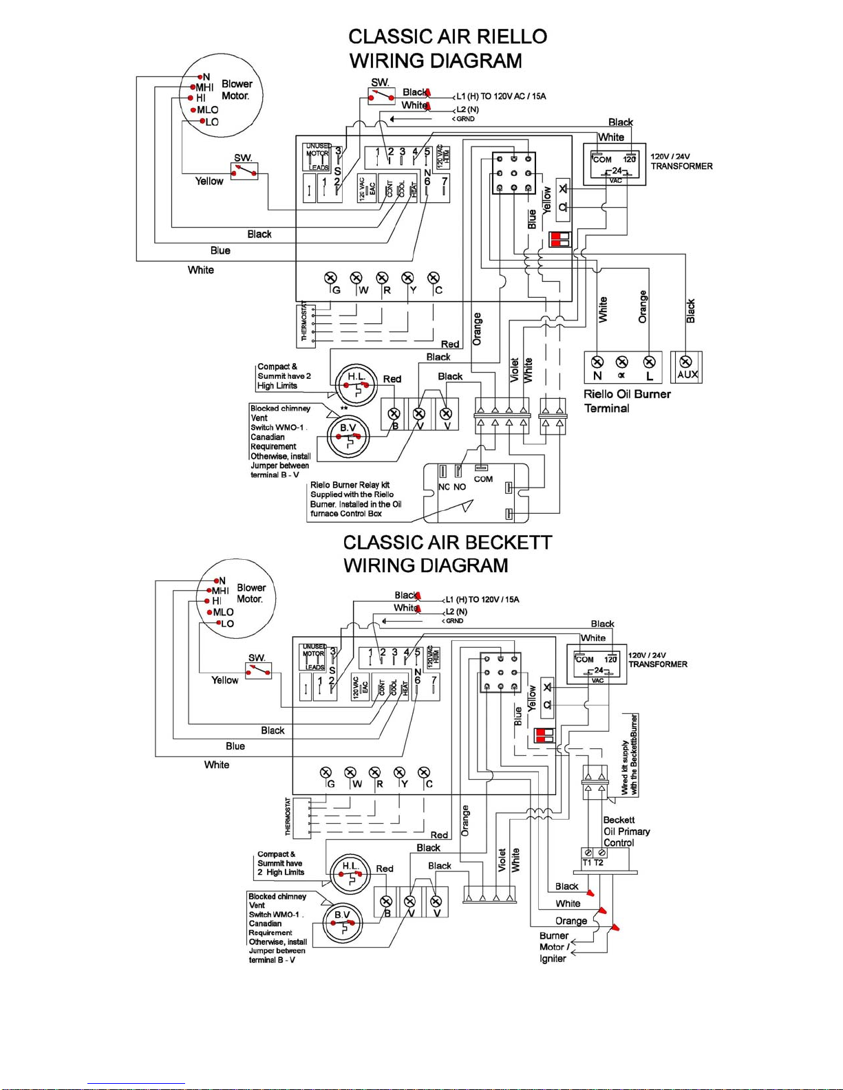
CLASSIC AIR WIRING DIAGRAM
FIGURE - 4
Page 25
Page 26
Page 27
Page 28
Page 29
Page 30
Page 31
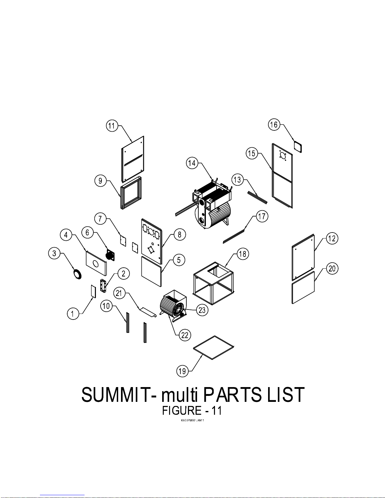
Page 32
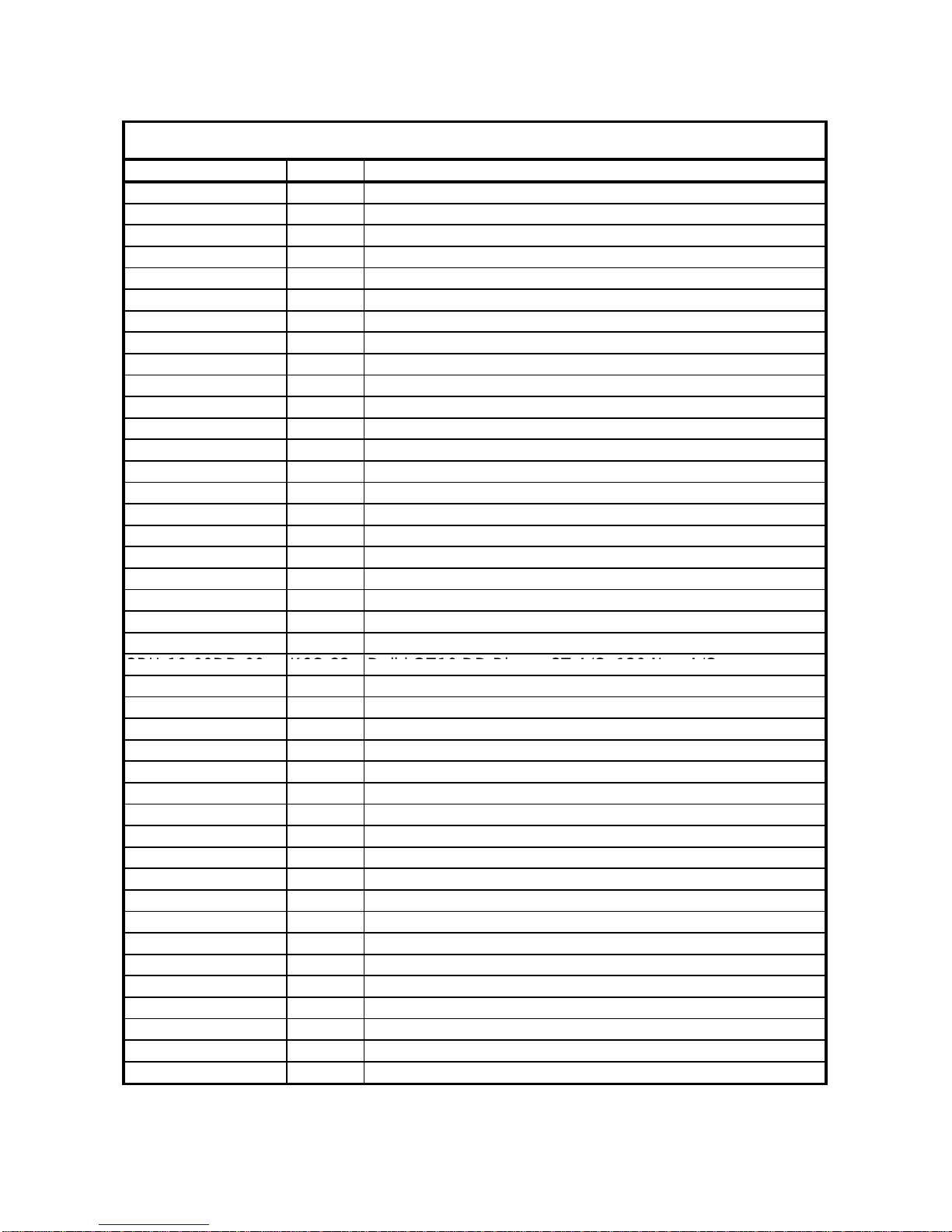
Table - 1
3BU-10-00DD-00
K6C-22
Delhi GT10 DD Bl
A/C, 120 N
A/C
Summit-multi Classic Air Oil-Fired Furnace
Order No. Item No. Part Description
ELB-P0-0008-00 K6C-1 Wiring Box Cover
ELB-P0-0006-00 K6C-2 Wiring Box
K00-CB-0103-00 K6C-3 5" Flue Pipe Collar
K6C-CB-0045-00 K6C-4 Cabinet Cleanout Cover
K6C-CB-0036-00 K6C-5 Cabinet Bl ower Door
K00-HE-0100-00 K6C-6 Smoke Pipe Flange Assembly
K00-CB-0037-00 K6C-7 Cleanout Cover Plates (Set)
K6C-CB-0100-00 K6C-8 Front Panel A ssembly On Or After Jan 24/07
K6C-CB-0200-00 K6C-8A Front Panel Assembly Prior To Jan 24/07 (Not Shown)
K6C-CB-0300-00 K6C-9 Filter Frame Assembly
K6C-CB-0039-00 K6C-10 Lower Front Corner Assembly (L/R)
K6C-CB-0021-00 K6C-11 Top Side Panel Assembly (Left)
K6C-CB-0020-00 K6C-12 Top Side Panel Assembly (Right)
K6C-CB-0046-00 K6C-13 Rear Gap Filler (Not Shown)
K6C-HE-0015-00 K6C-14 Heat Exchanger Assembly
K6C-CB-0400-00 K6C-15 Rear Panel Assembly
K6C-HE-0155-00 K6C-16 Flange Blank
K6C-CB-0062-00 K6C-17 Side Gap Filler
K6C-HE-0300-00 K6C-18 Divider / Base Assembly
K6C-CB-0038-00 K6C-19 Base Pan
K6C-CB-0010-00 K6C-20 Lower Side Panel
K00-CB-0028-00 K6C-21 Blower Key
ower 3T
3BU-12-00DD-00 K6C-23
Delhi GT12-10 DD Blower
5T A/C, 160 Non A/C
3BM-50-4SDD-00 K6C-24 Motor 1/2 Direct Driv e 4 S peed
3BM-75-4SDD-00 K6C-25 Motor 3/4 Direct Driv e 4 S peed
4CA-00-106M-2B K6C-26 Motor Run Capacitor (10 micro farad)
4CA-00-206M-2B K6C-27 Motor Run Capacitor (20 micro farad)
K00-BM-1050-00 K6C-28 Blower/Motor Assembly 1/2
K00-BM-1275-00 K6C-29 Blower/Motor Assembly 3/4
3SG-0P-1030-5A K6C-30 Sight Glass (Not Shown)
K00-HE-0104-0 K6C-31 Sight Glass Ring (Not Shown)
K00-HE-0020-00 K6C-32 Complete Gasket Set (Not Shown)
3BN-0F-3SBT-00 K6C-33 F3 Riello Burner (Short)
3BN-0F-5SBT-00 K6C-34 F5 Riello Burner (Short)
3BN-BF-3SBT-00 K6C-35 BF3 Riello Buner (Short) Direct Vent
3BN-BF-5SBT-00 K6C-36 BF5 Riello SBT Burner (Direct Vent)
K6C-37 Beckett Burner AFG Chasis
K6C-38 Beckett Burner NX Chasis
4CB-00-FAN0-00 K6C-39 ST9103 Classic Air Board
4SD-00-0160-00 K6C-40 165°F Snap Disk
4SW-00-BLVT-01 K6C-41 Blocked Vent Switch (Not Shown)
on
Please have serial number & date of manufacture ready when ordering parts
Jun-11
Page 33
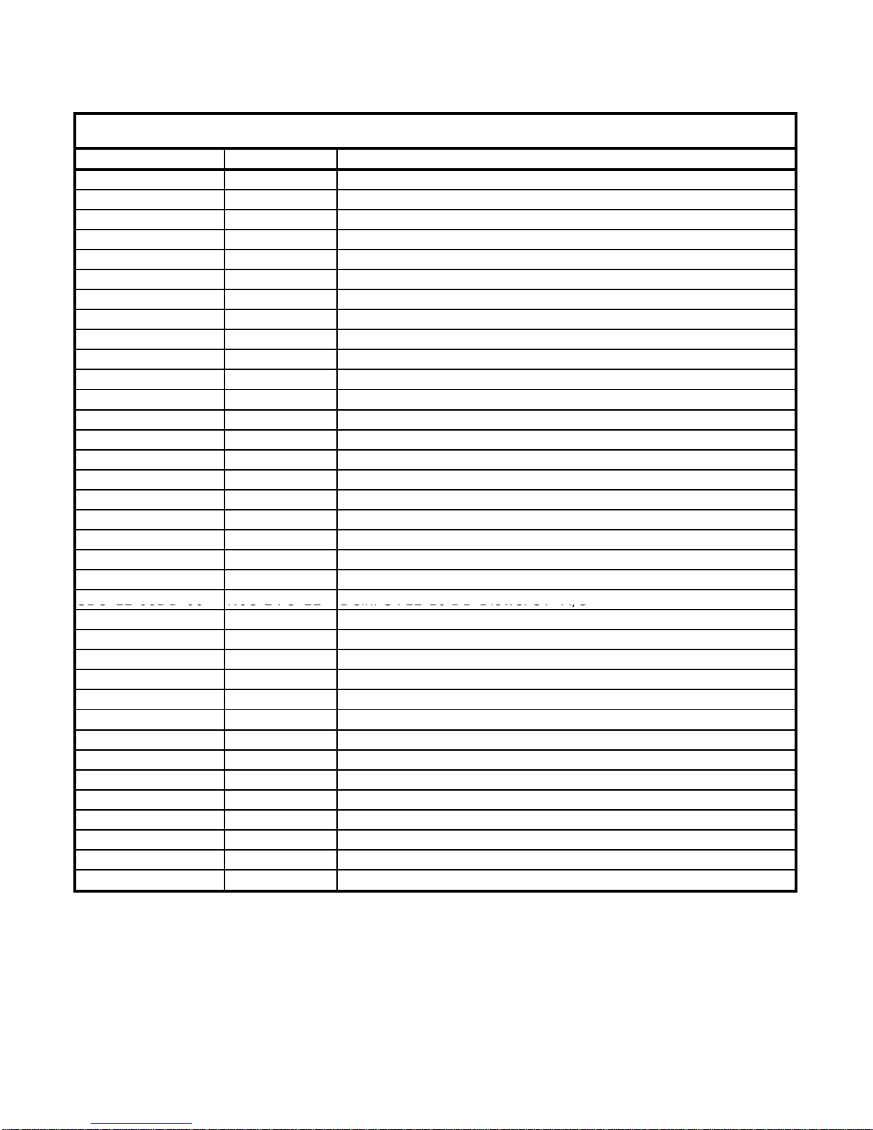
Table - 2
3BU 12 00DD 00
K6C EVO 22
Delhi GT12 10 DD Blower
5T A/C
Summit-multi EVO Oil-Fired Furnace
Order No. Item No. Part Description
ELB-P0-0008-00 K6C EVO-1 Wiring Box Cover
ELB-P0-0006-00 K6C EVO-2 Wiring Box
K00-CB-0103-00 K6C EVO-3 5" Flue Pipe Collar
K6C-CB-0045-00 K6C EVO-4 Cabinet Cleanout Cover
K6C-CB-0036-00 K6C EVO-5 Cabinet Blower Door
K00-HE-0100-00 K6C EVO-6 Smoke Pipe Flange Assembly
K00-CB-0037-00 K6C EVO-7 Cleanout Cover Plates (Set)
K6C EVO-8 Front Panel Assembly
K6C-CB-0300-00 K6C EVO-9 Filter Frame Assembly
K6C-CB-0039-00 K6C EVO-10 Lower Front Corner Assembly (L/R)
K6C-CB-0021-00 K6C EVO-11 Top Side Panel Assembly (Lef t)
K6C-CB-0020-00 K6C EVO-12 Top Side Panel Assembly (Right)
K6C-CB-0046-00 K6C EVO-13 Rear Gap Filler (Not Shown)
K6C-HE-0015-00 K6C EVO-14 Heat Exchanger Assembly
K6C-CB-0400-00 K6C EVO-15 Rear Panel Assembly
K6C-HE-0155-00 K6C EVO-16 Flange Blank
K6C-CB-0062-00 K6C EVO-17 Side Gap Filler
K6C-HE-0300-00 K6C EVO-18 Divider / Base Assembly
K6C-CB-0038-00 K6C EVO-19 Base Pan
K6C-CB-0010-00 K6C EVO-20 Lower Side Panel
K00-CB-0028-00 K6C EVO-21 Blower Key
-
3BM-75-4SDD-00 K6C EVO-23 Motor 3/4 Direct Drive 4 Speed
4CA-00-206M-2B K6C EVO-24 Motor Run Capacitor (20 micro farad)
4CB-00-TEMP-01 K6C EVO-25 Heating Temperature Sensor (Not Shown)
K00-BM-1275-00 K6C EVO-26 Blower/Motor Assembly 3/4
3SG-0P-1030-5A K6C EVO-27 Sight Glass (Not Shown)
K00-HE-0104-0 K 6C EVO -28 Sight Glass Ring (Not Shown)
K00-HE-0020-00 K6C EVO-29 Complete Gasket Set (Not Shown)
4SD-00-0180-00 K6C EVO-30 Snap Disc Limit Control (180ºF) (Not Shown)
3BN-0F-5SBT-00 K6C EVO-31 F5 Riello Burner (Short)
4CB-00-0FLC-01 K6C EVO-32 9200i Furnace Control (Not Shown)
3BN-BF-5SBT-00 K6C EVO-33 BF5 Riello SBT Burner (Direct Vent)
4SW-00-BLVT-01 K6C EVO-36 Blocked Vent Switch (Not Shown)
-
K6C EVO-34 Beckett Burner AFG Chasis
K6C EVO-35 Beckett Burner NX Chasis
-
-
Please have serial number & date of man ufacture ready when ordering parts
Jun-11
Page 34
y
)
Table - 3
Summit-multi MAX Oil-Fired Furnace
Order No. Item No. Part Description
ELB-P0-0008-00 K6C MAX-1 Wiring Box Cover
ELB-P0-0006-00 K6C MAX-2 Wiring Box
K00-CB-0103-00 K6C MAX-3 5" Flue Pipe Collar
K6C-CB-0045-00 K6C MAX-4 Cabinet Cleanout Cover
K6C-CB-0036-00 K6C MAX-5 Cabinet Blower Door
K00-HE-0100-00 K6C MAX-6 Smoke Pipe Flange Assembly
K00-CB-0037-00 K6C MAX-7 Cleanout Cover Plates (Set)
K6C MAX-8 Front Panel Assembly
K6C-CB-0300-00 K6C MAX-9 Filter Frame Assembly
K6C-CB-0039-00 K6C MAX-10 Lower Front Corner Assembly (L/R)
K6C-CB-0021-00 K6C MAX-11 Top Side Panel Assembly (Left)
K6C-CB-0020-00 K6C MAX-12 Top Side Panel Assembly (Right)
K6C-CB-0046-00 K6C MAX-13 Rear Gap Filler (Not Shown)
K6C-HE-0015-00 K6C MAX-14 Heat Exchanger Assembly
K6C-CB-0400-00 K6C MAX-15 Rear Panel Assembly
K6C-HE-0155-00 K6C MAX-16 Flange Blank
K6C-CB-0062-00 K6C MAX-17 Side Gap Filler
K6C-HE-0300-00 K6C MAX-18 Divider / Base Assembly
K6C-CB-0038-00 K6C MAX-19 Base Pan
K6C-CB-0010-00 K6C MAX-20 Lower Side Panel
K00-CB-0028-00 K6C MAX-21 Blower Key
K6C MAX-22 Not Applicable
3BU-12-00DD-00 K6C MAX-23
3BM-10-ECM0-02 K6C MAX-24 Direct Drive, 1 hp ECM
K00-BM-1210-E4 K6C MAX-25 Blower/Motor Assembly 1 hp ECM
3SG-0P-1030-5A K6C MAX-26 Sight Glass (Not Shown)
K00-HE-0104-0 K6C MAX-27 Sight Glass Ring (Not Shown)
K00-HE-0020-00 K6C MAX-28 Complete Gasket Set (Not Shown)
K00-HE-0176-00 K6C MAX-29
3BN-0F-5SBT-00 K6C MAX-30 F5 Riello Burner (Short)
3BN-BF-5SBT-00 K6C MAX-31 BF5 Riello SBT Burner (Direct Vent)
4TF-00-25V0-00 K6C MAX-32 40VA Transformer (Not Shown)
4CB-00-TEMP-00 K6C MAX-33 Heating Temperature Sensor (Not Shown)
4SD-00-0180-00 K6C MAX-34 Snap Disc Limit Control (180°) (Not Shown)
4CB-00-ECML-00 K6C MAX-35 9300i Furnace Control (Not Shown)
K6C MAX-36 Beckett Burner AFG Chasis
K6C MAX-37 Beckett Burner NX Chasis
4SW-00-BLVT-01 K6C MAX-38 Blocked Vent Switch (Not Shown)
Delhi GT12-10 DD Blower 5T A/C
Secondar
Heat Exchanger Baffle - each (Not Shown
Please have serial number & date of manufacture ready when ordering parts
Jun-11
 Loading...