

Granby KLR-100, KLR-200, KLF-100, KLF-200 Installation, Operation And Service Manual

!
!
!
!
!
!
!
!
OIL FIRED LOBOY FURNACE -
85% + EFFICIENCY
!
K
LR-100
K
LR-200
K
LF-100
KLF
-200
!
!
!
!
!
!
!
KLR-100 & 200 KLF-100 KLF-200
!
!
!
!
!
!
!
!
!
!
!
Please read the manual in its entirety before beginning installation. This
manual must be kept with the boiler for future reference. For maintenance
or question, please refer to your installer – contractor directly.
!
18-06-2017 G2017-E1 Rev.I
Installation, Operation and
Service
Manual
INSTALLATIONS MUST MEET ALL LOCAL AND CODES THAT MAY
DIFFER FROM THIS

!
!
2!
TABLE OF
CONTENTS
!
!
1.0 IMPORTANT SAFETY ADVICE 2
!
!
2.0 PRODUCT INFORMATION 3
!
!
3.0 FURNACE INSTALLATION 7
!
!
4.0 ACCESSORIES INSTALLATION 9
!
!
5.0 BURNER INSTALLATION AND SPECIFICATIONS 11
5.1 ASSEMBLY & INSTALLATION OF BURNER 11
5.2 SET BURNER FOR EFFICIENT OPERATION 12
5.3 KLR TECHNICAL INFORMATION 14
5.4 KLF TECHNICAL INFORMATION 15
!
6.0 FURNACE OPERATION AND SETTINGS 16
6.1 BLOWER SETTING 16
6.2 FAN TIMER CONTROL BOARD (ST9103A1028) 17
6.3 (ST9103A10
28) CONTROL BOARD SEQUENCE 18
6.4 SERVICING – FAN TIMER (ST9103A1028) 19
!
7.0 SERVICE 21
!
8.0 ELECTRICAL / WIRING DIAGRAMS 24
HEATING & COOLING – RIELLO BURNER 24
HEATING & COOLING – BECKETT BURNER 25
HEATING ONLY (2 WIRES THERMOSTAT) 27
!
9.0 EXPLODED PARTS VIEW 28
KLR-100 28
KLR-200 30
KLF-100
(Coming soon, please call your Granby representative) ---
KLF-200 32
!
!
!
10. START-UP TEST RESULTS 34
!
! !

!
!
3!
!
1.0 IMPORTANT SAFETY ADVICE
!
!
Please read and understand this manual before installing, operating or servicing the furnace.
To ensure you have a clear understanding of the operating procedures of the unit please take
the time to read the IMPORTANT SAFETY ADVICE section of this manual.
!
WARNINGS
!
NEVER burn garbage or paper in the unit.
NEVER store combustible material around it.
DO NOT attempt to start burner when excess oil has accumulated, when unit is full of vapour or
when heat exchanger is very hot.
DO NOT use gasoline, crankcase draining’s or any oil containing gasoline.
!
CAUTION
!
DO NOT TAMPER WITH THE FURNACE OR CONTROLS, CALL A QUALIFIED BURNER
TECHNICIAN.
!
DANGER
!
Do not use this furnace as a construction heater. Use of this furnace as a construction heater
exposes it to abnormal conditions, contaminated combustion air and lack of air filtering.
Failure to follow this warning can lead to premature furnace failure which could result in a
fire hazard and/or bodily harm and/or material damage.
!
IMPORTANT
!
This manual contains instructional and operational information for the KLR / KLF OIL-FIRED
FURNACE. Read the instructions thoroughly before installing furnace or starting the burner.
Consult local authorities about your local FIRE SAFETY REGULATIONS. All installations must
be in accordance with local state or provincial codes. Improper installation will result in voiding of
warranty.
!
!
!
!
!
!
!
!
!
!
!
!
!
!
!
!! ! ! !!!KLR!!! ! ! ! ! ! !!!!KLF!
!
! !

!
!
4!
2.0 PRODUCT INFORMATION
!
!
CLEARANCE (minimum) TO COMBUSTIBLES
Top of Supply Plenum 1” (25 mm)
Front (Maintenance) 24” (610 mm)
Rear (Maintenance) 24” (610 mm)
Side – Non-Access 1” (25 mm)
Side – Access maintenance 24” (610 mm)
Flue Pipe 9” (229 mm)
Floor (Can be installed directly on combustible or non-combustible)
DRAFT PRESSURE
Breech draft pressure -0.01” WC minimum
BURNER TUBE INSERTION
Riello and Beckett 2-1/2” (63 mm)
AIR/BLOWER DATA
Maximum external static pressure 0.5” WC
Maximum cooling unit capacity KLR-100, up to 3.0 tons.
KLR-200, up to 5.0 tons.
KLF-100, up to 3.0 tons
KLF-200, up to 5.0 tons.
Maximum air temperature rise 85°F
High Limit temperature 185°F
MOTOR/BLOWER
KLR-100: 1/2 hp 4 Speed PSC / G10-8 DD or 1/2 hp 5 speed ECM / G10-8 DD
KLR-200: 3/4 hp 4 Speed PSC / GT12-10 DD or 3/4 hp ECM 5 speed / GT12-10 DD
KLF-100: 1/2 hp 4 Speed PSC / G10-8 DD or 1/2 hp ECM 5 speed / G10-8 DD
KLF-200: 3/4 hp 4 Speed PSC / GT12-10 DD or 3/4 hp ECM 5 speed / GT12-10 DD
FAN/HIGH LIMIT CONTROL
Honeywell ST9103A1028 Fan Center & Thermo-Disk (7” stem)
FLUE-PIPE CONNECTION
5” breech
CLEANOUTS
Rear breech cover & burner opening (KLR) or Front breech & burner opening (KLF)
THERMOSTAT
Any wall thermostat
Thermostat adjustment as per thermostat manufacturer installation.
!
!
5!
FUEL
Not heavier than No. 2 furnace oil.
ELECTRICAL – 120 Volts, 1PH-60 Hz, 15 amps. circuit protection, USA circuit protection 20 amps.
AIR FILTERS
KLR-100 20” x 20” x 2” non-pleated UL approved
KLR-200 15” x 20” x 2” & 20” x 20” x 2” non-pleated UL approved
KLF-100 20” x 20” x 2” non-pleated UL approved
KLF-200 15” x 20” x 2” (2X) non-pleated UL approved
PLENUM DIMENSIONS (KLR-100)
Cold air return
(A)
20” x 20”
(508 x 508 mm)
Hot air supply
(B)
20” x 20”
(508 x 508 mm)
Plenum spacing
(C)
2”
(51 mm)
PLENUM DIMENSIONS (KLR-200)
Cold air return
(A)
20” x 22”
(508 x 559 mm)
Hot air supply
(B)
20” x 24”
(508 x 610 mm)
Plenum spacing
(C)
2”
(51 mm)
PLENUM DIMENSIONS (KLF-100)
Cold air return
(A)
18” x 20-3/4”
(457 x 527 mm)
Hot air supply
(B)
18” x 21-3/4”
(457 x 552 mm)
Plenum spacing
(C)
2-1/8”
(54 mm)
PLENUM DIMENSIONS (KLF-200)
Cold air return
(A)
20” x 20”
(508 x 508 mm)
Hot air supply
Plenum spacing
(B)
(C)
20” x 24”
2”
(508 x 610 mm)
(51 mm)
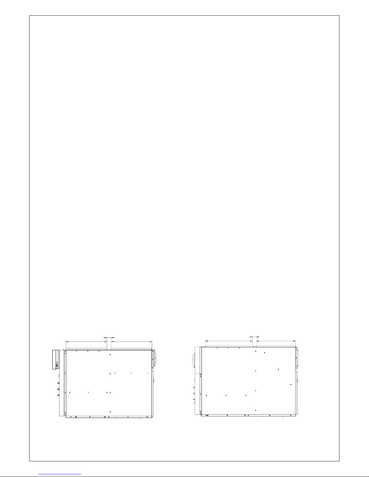
B C A B C A
KLR KLF
!
!
6!
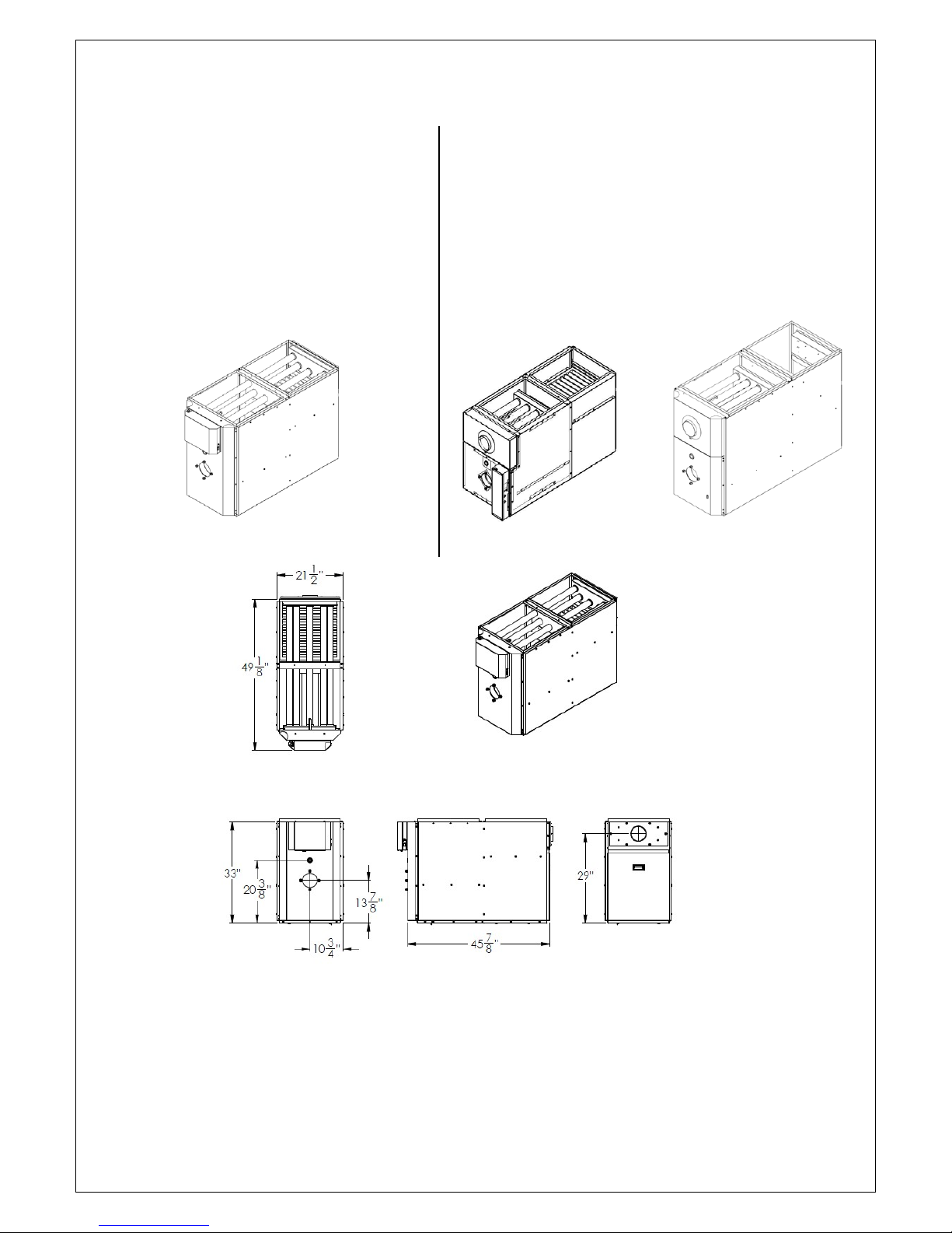
KLR KLF
DIMENSIONS (KLR-100) DIMENSIONS (KLF-100))
Depth
49-1/8”
(1248 mm)
Depth
53-1/2”
(1,359 mm)
Height
33”
(838 mm)
Height
29-3/8”
(746 mm)
Width
21-1/2”
(546 mm)
Width
21-1/2”
(546 mm)
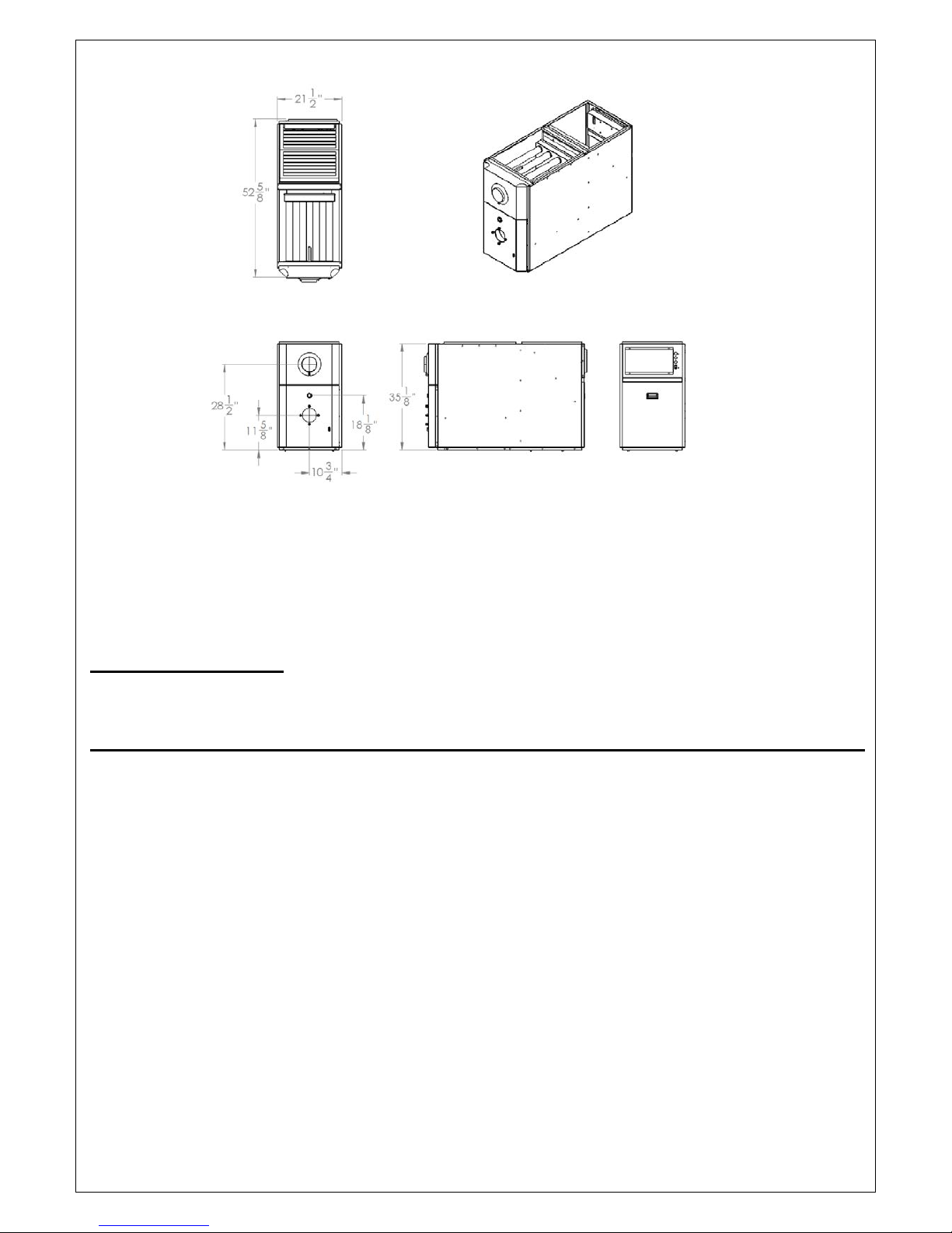
DIMENSIONS (KLR-200) DIMENSIONS (KLF-200)
Depth
55-1/8”
(1400 mm)
Depth
52-5/8”
(1337 mm)
Height
33”
(838 mm)
Height
35-1/8”
(892 mm)
Width
21-1/2”
(546 mm)
Width
21-1/2”
(546 mm)
KLR KLF-100 KLF-200
KLR-100 - DIMENSIONS
Dimensions are in inches

!
!
7!
KLR-200 – DIMENSIONS
Dimensions are in inches
KLF-100 - DIMENSIONS
Dimensions are in inches
!
!
8!
KLF-200 – DIMENSIONS
Dimensions are in inches
3.0 FURNACE INSTALLATION
OIL TANK & PIPING
Tank installation must conform to local requirements.
Install according to the applicable code such as CAN/CSA B139 and NFPA 31 in the USA.
Minimize number of connections in suction line and make all connections air tight. Use a pipe
joint compound suitable for oil on all pipe threads. To reduce possibility of air leaks, tighten
stem packing gland nut on any valves installed in the suction line. Also, be sure the oil filter is tight,
as filter gaskets often shrink. Check for kinks in the oil lines as well as for possible air pockets and
for loose connections. Two filters as shown below are recommended. Optional tank gauge
protectors and outlet protectors are available at your local dealer.
ONE PIPE SYSTEM Where the tank outlet is above the burner and when the oil flows by gravity
to the oil pump, a single-stage fuel unit with a single oil line to the pump
may be used.
TWO PIPE SYSTEM When a single line is not suitable, use double line or contact your dealer
for special oil line fittings. Install by-pass plug on burner fuel pump as
specified in the burner manual.

!
!
9!
REAR FLUE FURNACE ILLUSTRATION
Oil Tank and Piping
PLACEMENT & VENTING
Furnace installation shall conform to the required installation code for oil-fired equipment
(USA: NFPA 31, Canada: CAN/CSA B139).
FLOOR SUPPORT COMBUSTIBLE – If required, support furnace on five (5) concrete blocks.
Make sure the center of the furnace base is supported. For a furnace
installed on a combustible floor, consult the applicable code and authorities
having jurisdiction on this application. The floor must support the weight.
CHIMNEY/VENT Connect the furnace to a chimney/vent system of size and condition required
by the NFPA 31 (USA) or CAN/CSA B139 (Canada) code. Furnace is
approved for factory built chimney type “L” vents. Breech is certified for 5”
vent pipe. Keep vent/flue pipe as short as possible with min. 1/4” per foot
upward slope. Vent/flue pipes MUST NOT pass through a ceiling. Maximum
flue gas temperature is 575°F.
PRESENCE OF CONDENSATION
IN THE CHIMNEY OR FLUE PIPE
Presence of condensation in your chimney or flue pipe is not normal, all
necessary precautions should be taken to prevent condensation build-up in the
flue pipe and inside the chimney. Make sure that the chimney size is according
to the tables in CAN/CSA B139 / NFPA 31.
Note: Base temperature — the temperature of the flue gases at the base of
the chimney flue, measured within the vent at the base tee or vent connector
thimble, with the barometric damper shut, after the appliance flue-gas
temperature has stabilized.

!
!
10!
The temperature at the base of the chimney can be increased by insulating the
flue-pipe between the furnace and the chimney base. If this is not sufficient,
consider cutting or removing some flue baffles in the furnace. BE AWARE
THAT REMOVING BAFFLES REDUCES THE UNIT’S EFFICIENCY AND A
MODIFIED UNIT IS NO LONGER ENERGY STAR® CERTIFIED.
ELECTRICAL Wire according to the National Electrical Code (Canadian Electrical Code in
Canada) or local codes. Use a separately fused #12 electrical line directly
from the service panel to the furnace junction box. Install a manual shut-off
switch at the door or stairway to furnace room so furnace can be shut off
remotely.
COMBUSTION & Install openings and ductwork to the furnace room providing fresh out-
VENTILATION AIR side combustion and circulation air for cooling the furnace casing, as
installation code requires (USA NFPA 31, Canada CAN/CSA B139). If
installed in a closed room, provide two free air ventilation openings of at least
8” x 12” (96 sq. in.) free flow area near ceiling and floor. Oil burners
must have sufficient air to allow vent systems to operate properly.
!
!
11!
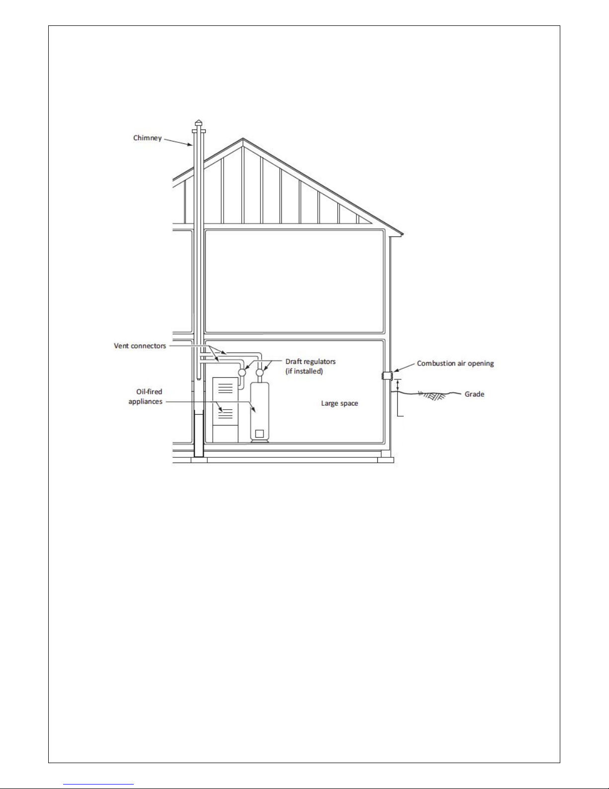
Appliance(s) located in a large space
Combustion air and additional ventilation from outdoor
The opening shall have a total free-flow area of not less than 4,4 cm2/kW (1 po2/5000 BTU/h) of the
total input rating for the appliance(s) located in a large space.
12’’ higher than ground level
and snow forecast.!
!
!
12!
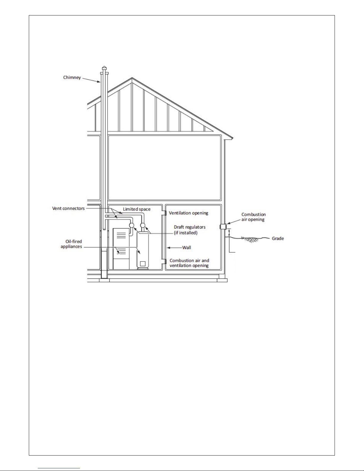
Appliance(s) located in a limited space
Combustion air from outdoors by infiltration and ventilation from inside the building
The opening shall have a total free-flow area of not less than 4,4 cm2/kW (1 po2/5000 BTU/h) of the
total input rating for the appliance(s) located in a limited space.
Each ventilation opening through the inside wall (venting opening of the combustion air and
ventilation opening) shall have a free-flow area of not less than 22 cm2/kW (1 po2/1000 BTU/h) of
the input rating of the appliance(s) located in the limited space.
4.0 ACCESSORIES INSTALLATION
BLOCKED VENT SWITCH (BVSO)
(FOR CANADIAN INSTALLATION ONLY)
Oil-fired appliances installed in Canada require a blocked vent switch system when installed on a
chimney. A safety switch is included with the furnace to perform this function. It is the installer’s
responsibility to install the switch in accordance with the instructions provided. Not applicable for
direct vent systems. Field Controls Model: WMO-1 (Manual Reset)
12’’ higher than ground level
and snow forecast.!
 Loading...