

Granby KHM SERIES, KHM-100, KHM-200 Nstallation, Operation And Service Manual
Installation, Operation and
Service Manual
KHM
SERIES
85% + EFFICIENCY
OIL FIRED HI-BOY FURNACE
KHM-100
KHM-200
KHM-100 Illustration
INSTALLATIONS MUST MEET ALL LOCAL AND FEDERAL
CODES THAT MAY DIFFER FROM THIS MANUAL
Please read the manual in its entirety before beginning installation.
This manual must be kept with the furnace for future reference.
GRANBY FURNACES INC.
PO Box 637
12118 Hwy 209
Parrsboro Nova Scotia Canada
B0M 1S0
902-254-2543
www.granbyindustries.com
01-30-2014 G2012-E2 Rev. F

1
TABLE OF CONTENTS
1.0 IMPORTANT SAFETY ADVICE 2
2.0 PRODUCT INFORMATION
3
3.0 FURNACE INSTALLATION
6
4.0 ACCESSORY INSTALLATION
9
5.0 BURNER INSTALLATION AND SPECIFICATIONS 13
5.1 ASSEMBLY & INSTALLATION OF BURNER 13
5.2 SET BURNER FOR EFFICIENT OPERATION 14
5.3 TECHNICAL INFORMATION 16
6.0 FURNACE OPERATION AND SETTINGS 17
6.1 BLOWER SETTING 17
6.2 FAN TIMER CONTROL BOARD (ST9103 A 1028) 18
6.3 ST9103 A 1028 CONTROL BOARD SEQUENCE 19
6.4 SERVICING – FAN TIMER (ST9103 A 1028) 20
7.0 SERVICE 22
8.0 ELECTRICAL / WIRING DIAGRAMS 25
HEATING / COOLING – RIELLO BURNER 25
HEATING / COOLING – BECKETT BURNER 26
HEATING ONLY (2 WIRES THERMOSTAT) 28
9.0 EXPLODED PARTS VIEW 29
KHM-100 29
KHM-200 31
10. START-UP TEST RESULTS 33
2
1.0 IMPORTANT SAFETY ADVICE
Please read and understand this manual before installing, operating or servicing the
furnace. To ensure you have a clear understanding of the operating procedures of the
appliance please take the time to read the IMPORTANT SAFETY ADVICE section of this
manual.
WARNINGS
NEVER burn garbage or paper in the unit.
NEVER store combustible material around it.
DO NOT attempt to start burner when excess oil has accumulated, when unit is full of vapour
or when heat exchanger is very hot.
DO NOT use gasoline, crankcase drainings or any oil containing gasoline.
CAUTION
DO NOT START THE BURNER UNTIL ALL FITTINGS, COVERS AND DOORS ARE IN
PLACE. DO NOT TAMPER WITH THE FURNACE OR CONTROLS, CALL A QUALIFIED
BURNER TECHNICIAN. DO NOT STORE OR USE GASOLINE OR OTHER FLAMMABLE
VAPOURS AND LIQUIDS IN THE VICINITY OF THIS UNIT OR ANY OTHER APPLIANCE.
DANGER
Do not use this furnace as a construction heater. Use of this furnace as a construction
heater exposes it to abnormal conditions, contaminated combustion air and lack of air
filtering. Failure to follow this warning can lead to premature furnace failure which
could result in a fire hazard and/or bodily harm and/or materials damages.
IMPORTANT
This manual contains instructional and operational information
for the KHM OIL-FIRED FURNACE. Read the instructions
thoroughly before installing furnace or starting the burner.
Consult local authorities about your local FIRE SAFETY
REGULATIONS. All installations must be in accordance with
local state or provincial codes. Improper installation will result
in voiding of warranty.

3
2.0 PRODUCT INFORMATION
CLEARANCE (minimum) TO COMBUSTIBLES
UPFLOW POSITION
Top & Sides of Supply Plenum 1” (25 mm)
Front (Maintenance) 24” (610 mm)
Rear 0” (0 mm)
First Side 0” (0 mm)
Other Side 0” (0 mm)
Flue Pipe 9” (229 mm)
Floor Combustible
DOWNFLOW POSITION
Top 2” (51 mm)
Bottom and Sides - Plenum 1” (25 mm)
Rear 0” (0 mm)
First Side 0” (0 mm)
Other Side 0” (0 mm)
Front (Maintenance) 24” (610 mm)
Flue Pipe 9” (229 mm)
Floor (with Down flow base) Combustible
HORIZONTAL POSITION
Top 2” (51 mm)
Bottom and Sides - Plenum 1” (25 mm)
Rear 1” (25 mm)
First Side 1” (25 mm)
Other Side 1” (25 mm)
Front (Maintenance) 24” (610 mm)
Flue Pipe 9” (229 mm)
Floor 2” (51 mm)
DRAFT PRESSURE
Breech draft pressure -0.01” wc minimum
AIR/BLOWER DATA
External static – Non A/C 0.2” wc
External static – A/C 0.5” wc
Maximum cooling 3.0 tons… KHM-100
5.0 tons… KHM-200
Maximum air temperature rise See page 16 and 34
High Limit, max design outlet temp 185°F
Thermostat anticipator 0.2 amps
MOTOR/BLOWER
KHM-100: 1/2 hp 4 Speed / G10-8 DD or 1/2 hp ECM / G10-8
KHM-200: 3/4 hp 4 Speed / GT12-10DD or 3/4 hp ECM / GT12-10
4
FAN/HIGH LIMIT CONTROL
Honeywell ST9103 Fan Center & Thermo-Disk (7” stem)
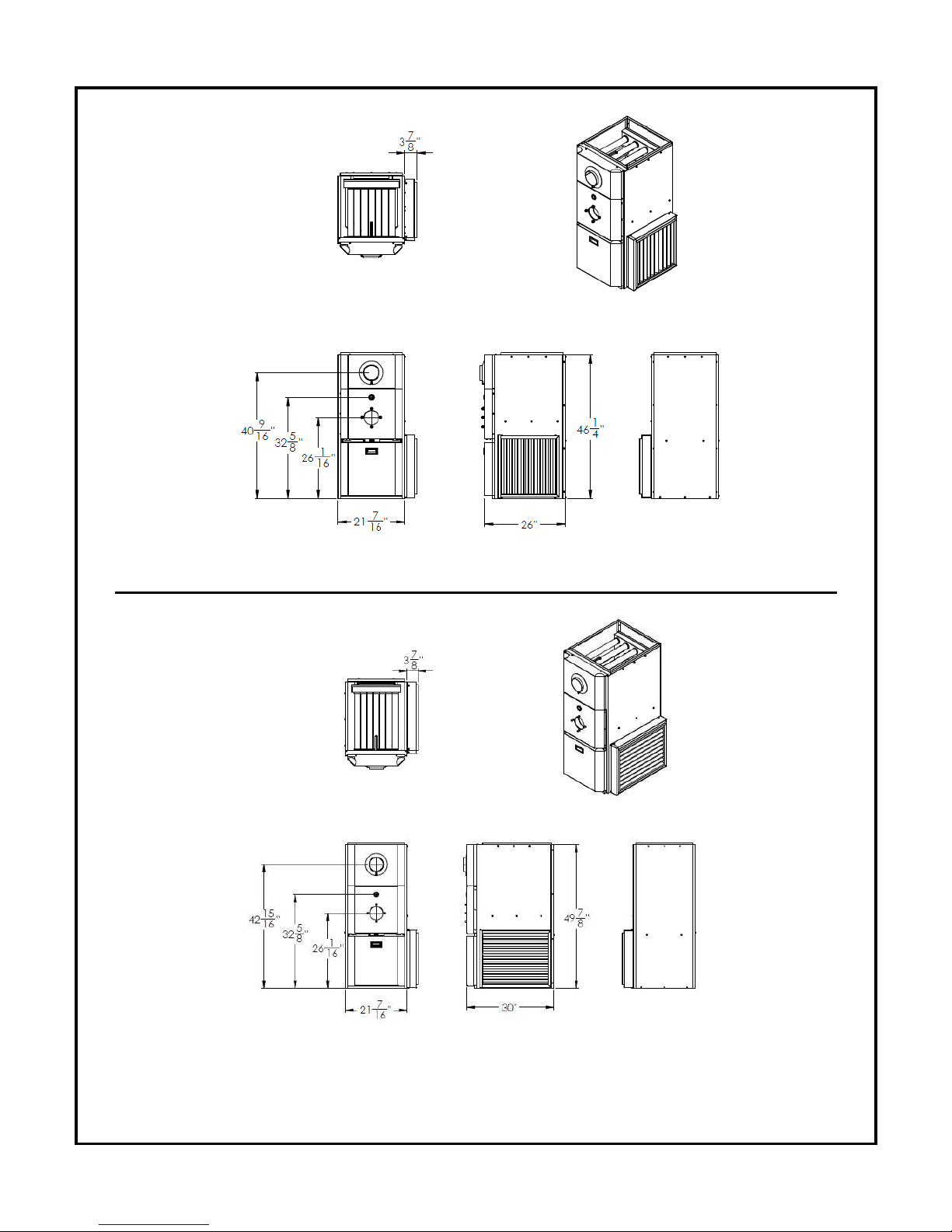
DIMENSIONS (KHM-100)
Depth 26” (660 mm)
Height 46 1/4” (1175 mm)
Width 21 7/16” (545 mm)
DIMENSIONS (KHM-200)
Depth 30” (762 mm)
Height 49 7/8” (1267 mm)
Width 21 7/16” (545 mm)
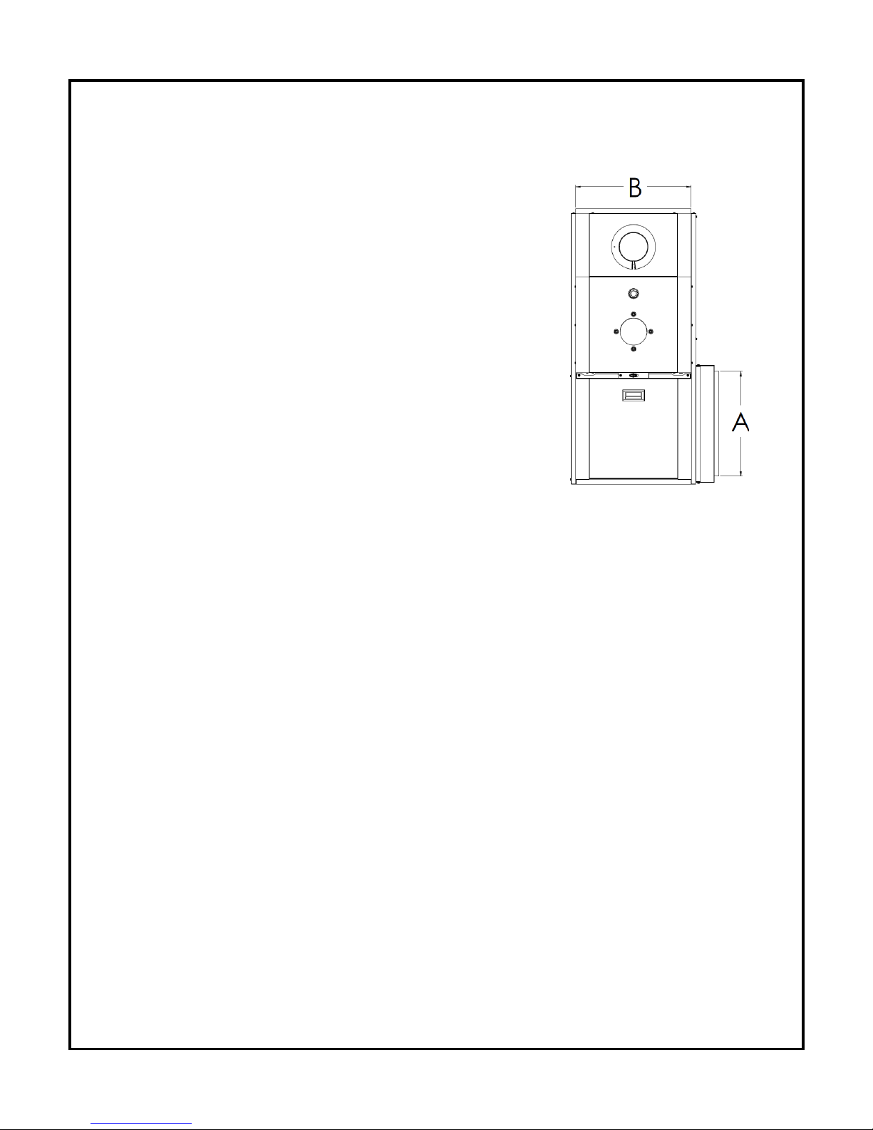
PLENUM DIMENSIONS (KHM-100)
Cold air return (A) 18” x 18” (457 x 457 mm)
Hot air supply (B) 20” x 20” (508 x 508 mm)
PLENUM DIMENSIONS (KHM-200)
Cold air return (A) 23” x 18” (584 x 457 mm)
Hot air supply (B) 24” x 20” (610 x 508 mm)
AIR FILTERS
KHM-100 20” x 20” x 2” non-pleated UL approved
KHM-2 00 25” x 20” x 2” non-pleated UL approved
A/C COIL LOCATION
Minimum height above the heat exchanger 6” (152 mm)
See A/C Coil Manufactures Requirements
SMOKE-PIPE CONNECTION
5” Chimney or direct vent DVS Granby kit
CLEANOUTS
Front Cover & Burner Opening
THERMOSTAT
Any thermostat
FUEL
Not heavier than No. 2 furnace oil.
ELECTRICAL – 120 Volts, 60 Hz
Canada Less than 12 amps, circuit protection 15 amps.
USA 13.3 amps, circuit protection 20 amps.
5
KHM-100 - DIMENSIONS
Dimensions are in inches
KHM-200 - DIMENSIONS
Dimensions are in inches
6
3.0 FURNACE INSTALLATION
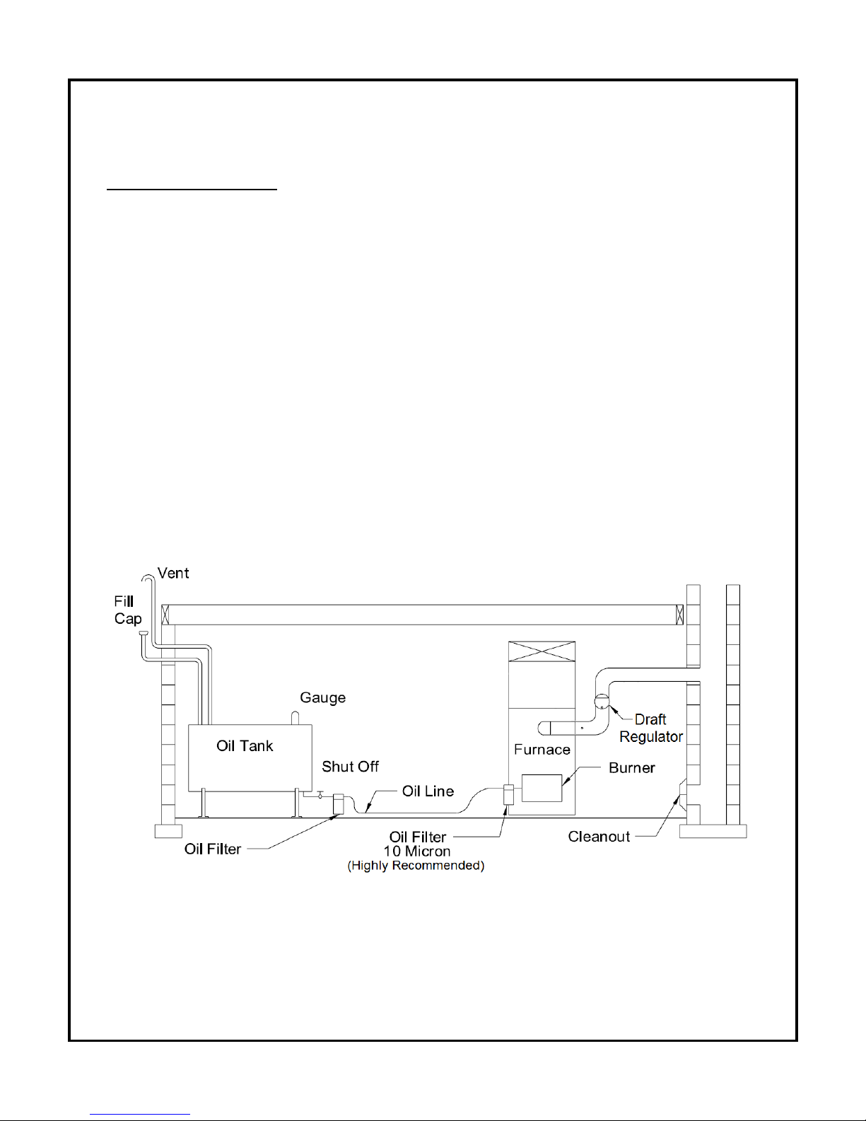
OIL TANK & PIPING
Tank installation must conform to local requirements.
Install according to the applicable code such as CSA B139 and NFPA 31. Minimize the
number of connections in suction line and make all connections as tight as possible. Use a
pipe joint compound suitable for oil on all pipe threads. To reduce possibility of air leaks,
tighten stem packing gland nut on any valves installed in the suction line. Also, be sure the oil
filter is tight, as filter gaskets often shrink. Check for kinks in the oil lines as well as for
possible air pockets and for loose connections. Two filters as shown below are recommended.
Optional tank gauge protectors and outlet protectors are available at your local dealer.
ONE PIPE SYSTEM Where the tank is above the burner and when the oil flows by
gravity to the oil pump, a single-stage fuel unit with a single oil line
to the pump may be used.
TWO PIPES SYSTEM When a single line is unsuitable, use a double line system or see
your dealer for special oil line fittings. Install by-pass plug on burner
fuel unit as specified in the burner manual.
Oil Tank and Piping
7
PLACEMENT & VENTING
Furnace installation shall conform to the required installation code for oil-fired equipment (USA:
NFPA 31, Canada: CSA B139).
FLOOR SUPPORT COMBUSTIBLE – If required, support furnace on five (5) concrete
blocks. Make sure the center of the furnace base is supported.
Approved for installation on combustible floors in the upflow position and
downflow position (with the optional sub-base). Not approved for
installation on combustible floor in horizontal applications. For horizontal
applications, use railing type support (not supplied) to keep the furnace
in position. Make sure that all clearances are respected.
CHIMNEY/VENT Connect the furnace to a chimney/vent system of size and condition
required by the NFPA 31 (USA) or CSA B139 (Canada) code. Furnace
is approved for factory built chimney type “L” vents. Breech is certified
for 5” vent pipe. Keep vent/flue pipe as short as possible with a
minimum upward slope of ¼’’ per foot. Vent/flue pipes MUST NOT pass
through a ceiling. Maximum flue gas temperature is 575°F.
CONDENSATION If you have condensation in your chimney, make sure that the
chimney size is according to the tables in CSA B139 / NFPA 31.
The temperature at the entrance of the chimney can be increased
by insulating the flue-pipe between the furnace and the chimney
base. If this is not sufficient, consider cutting or removing some
flue baffles in the furnace. BE AWARE THAT REMOVING BAFFLES
REDUCES THE UNIT EFFICIENCY AND A MODIFIED UNIT IS NO
LONGER ENERGY STAR APPROVED.
COMBUSTION &
Install openings and ductwork to the furnace room providing fresh
VENTILATION AIR outside combustion and circulation air for cooling the furnace casing, as
installation code requires (USA NFPA 31, Canada CSA B139). If
installed in a closed room, provide two free air ventilation openings of at
least 8” x 12” (96 sq. in.) free flow area near ceiling and floor. Oil burners
must have sufficient air to allow vent systems to operate properly.
DRAFT Use approved draft control supplied for 5” pipe. Set specified draft
minimum pressure of -0.01” wc.
ELECTRICAL Wire according to the National Electrical Code (Canadian Electrical
Code in Canada) or local codes. Use a separately fused #12 electrical
line directly from the service panel to the furnace junction box. Install a
manual shut-off switch at the door or stairway to furnace room so
furnace can be shut off remotely.
CLEARANCES Before placing unit, review installation clearances as shown on furnace
operating decal or section PRODUCT INFORMATIONS.
LOCATION Install the furnace close to chimney and central to ductwork.
8
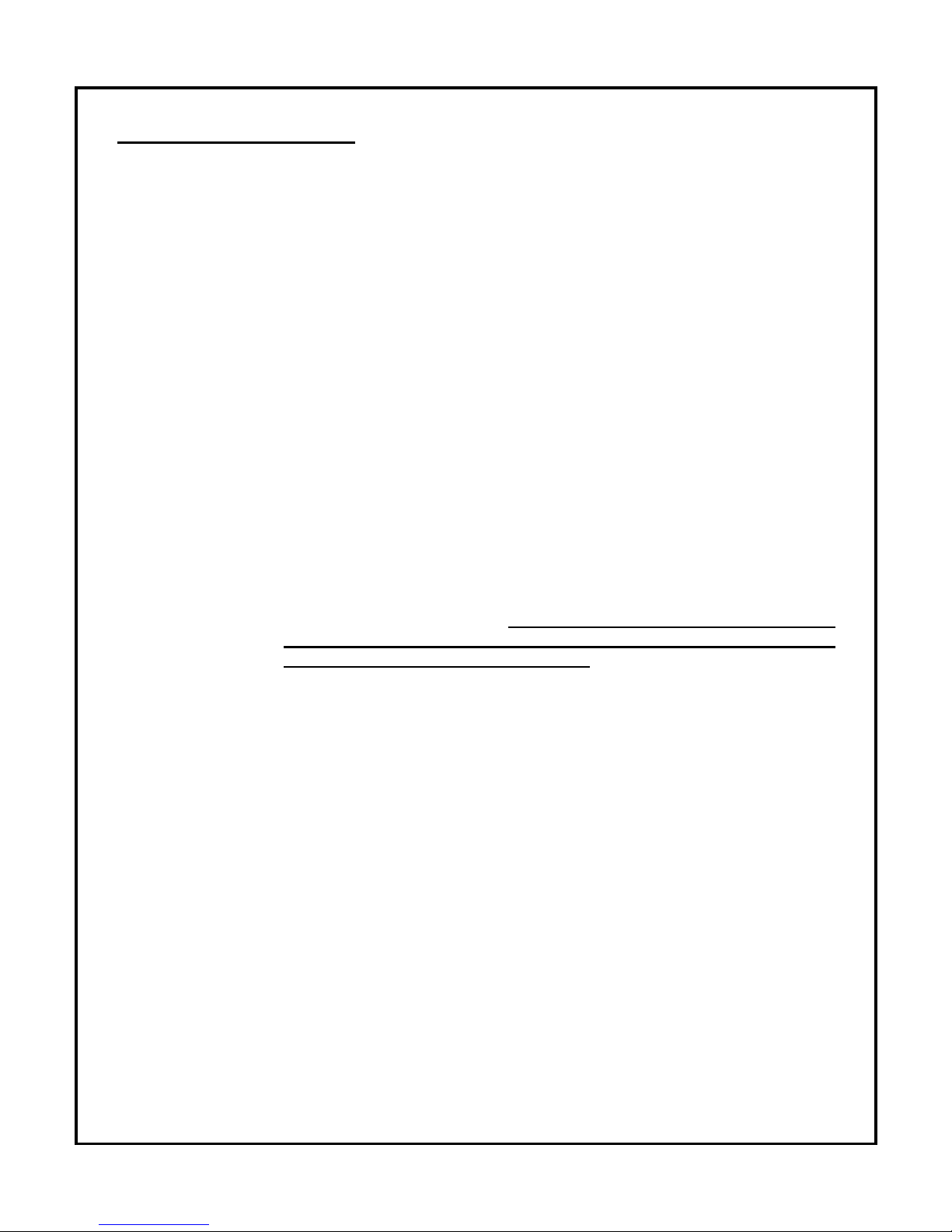
MULTI-POSITION CONFIGURATIONS
UPFLOW INSTALLATION DOWNFLOW INSTALLATION
The return air opening can be located
on left side or on the right side of the
unit. After installing the filter rack
supplied with the unit we recommend
installing the blower door before
handling the unit.
HORIZONTAL INSTALLATION
When the unit is installed in the horizontal configuration on a combustible floor with a choice of
right or left air outlet, the clearance of (2’’) from combustible material must be taken into
consideration.
The burner must always be installed facing upwards regardless of the
configuration installation.
For complete clearance information to combustibles, see PRODUCT
INFORMATION, page 3.
WARM AIR
AIR RETURN
WARM AIR
AIR RETURN
WARM AIR
AIR RETURN
Filter
Filter
Downflow
Sub-base
Filter
When the unit is installed in downflow
configuration on a combustible floor, the
clearance from combustible material must be
respected. The downflow sub-base
CAB-A0-0045-00 (for KHM-100) or
CAB-A0-0046-00 (for KHM-200) can be used
to ensure these clearances.
9
4.0 ACCESSORY INSTALLATION
BLOCKED VENT SWITCH (BVSO) FOR CANADIAN APPLICATION ONLY
Oil-fired appliances installed in Canada require a blocked vent switch system when installed on
a chimney. A safety switch is included with the furnace to perform this function. It is the
installer’s responsibility to install the switch in accordance with the instructions provided. Not
applicable for Direct Vent systems. Field Controls Model: WMO-1 (Manual Reset)
Switch Operation
Blocked vent switches are flue gas safety devices for detecting spillage of flue gases due to a
blocked flue or inadequate draft. After detecting a problem, the switch de-energizes the
system’s burner control.
NEVER reset the switch unless the cause of the blockage has been corrected.
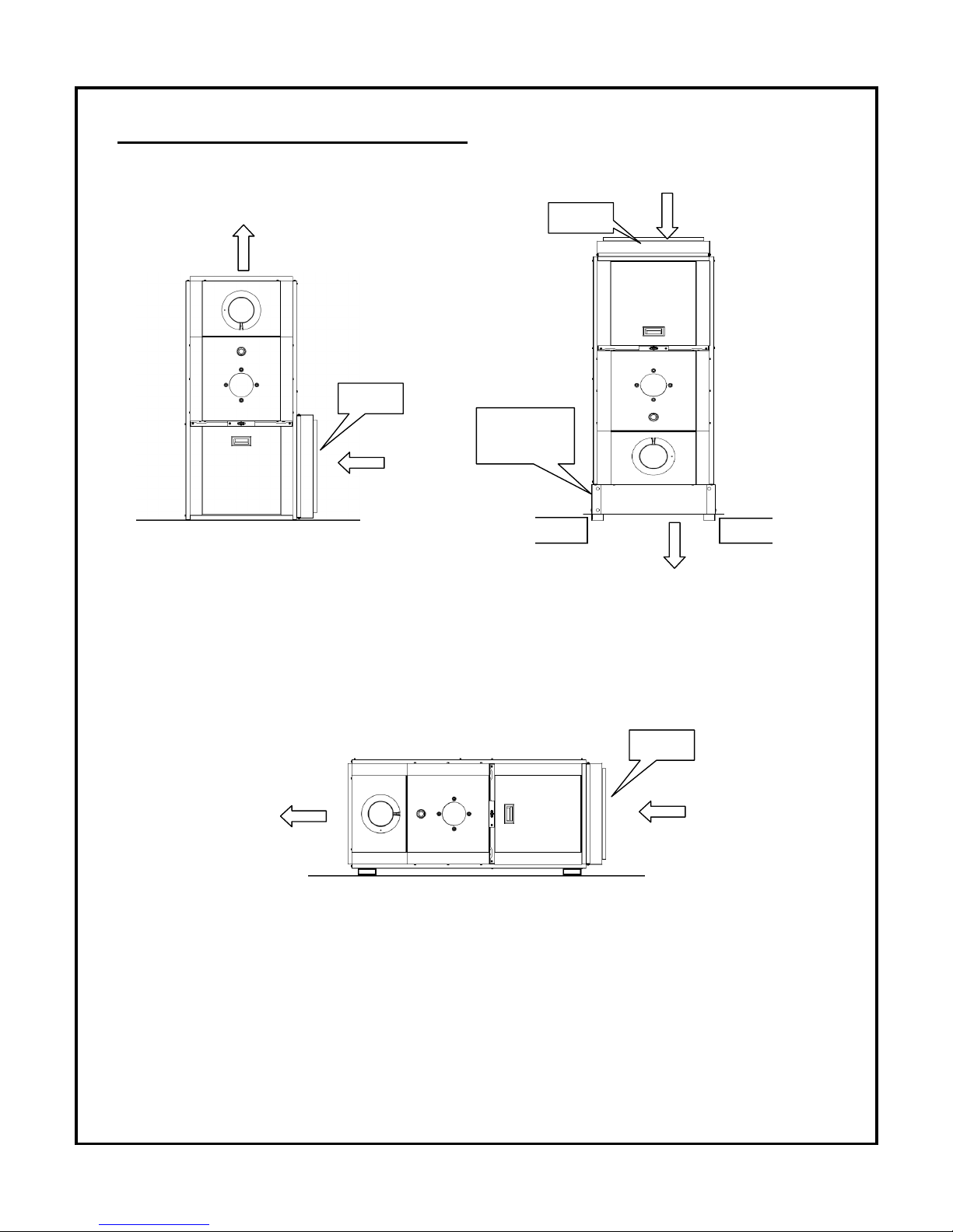
Installation (Figure 1)
1) Drill a 5/8” hole in to the flue vent pipe near the appliance breech connection.
2) This hole must be before the draft regulator, vertically or horizontally.
3) Remove one of the securing nuts from the threaded tube of the safety switch.
4) Tighten the other securing nut onto the pipe as far as possible.
5) Insert the threaded tube end into the pierced hole of the flue vent pipe.
6) Install the securing nut on the safety switch tube, which protrudes into the flue vent pipe.
Tighten the nut securely.
Figure 1-
Illustration from the instruction
Figure 2- BVSO wiring diagram
manual of Field Controls
Wiring Instructions (BVSO)
Caution: Disconnect the electrical power when wiring the unit.
Wire the blocked vent switch in accordance with The National Electrical Code and applicable
local codes. Wire the safety switch (BVSO) in series with the thermostat and the fan timer
relay control (Figure 2).
10
System Test Procedure (BVSO)
1) With the power re-established, block the chimney or vent pipe downstream of the switch.
2) Adjust the thermostat to call for heat.
3) Once the heating system has started the blocked vent switch should shut down the burner
within 10 minutes or sooner.
4) Once the system has cooled, the blocked vent switch can manually be reset.
5) This procedure should be tested a second time.
6) After testing the blocked vent switch the chimney should be cleared of obstruction and the
heating system should be tested over a long run cycle.
If the block vent switch shuts down the system, check to ensure there is enough draft in the
chimney and venting pipes.
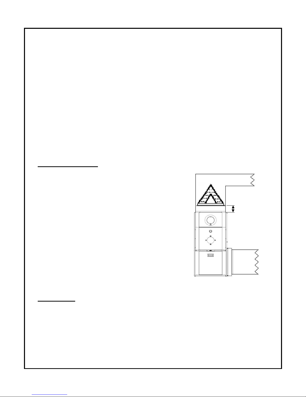
AIR CONDITIONING
An air conditioning coil may be installed on the supply side
only. Coils installed on the return side will cause
condensation on the heat exchanger; this will shorten the heat
exchanger life and may cause products of combustion to enter
the house. Wire as per wiring label and diagram. Height of
the coil above the unit supply shall be at least 4” (102
mm).
See A/C coil Manufacturers Requirements.
To check the AC coil total air flow resistance,
see procedure at page 34.
HUMIDIFIER
If a humidifier is installed ensure that no water can drip or run from it into the furnace. This
would cause deterioration and void the furnace warranty.
4 inch
minimum
 Loading...