

Page 1
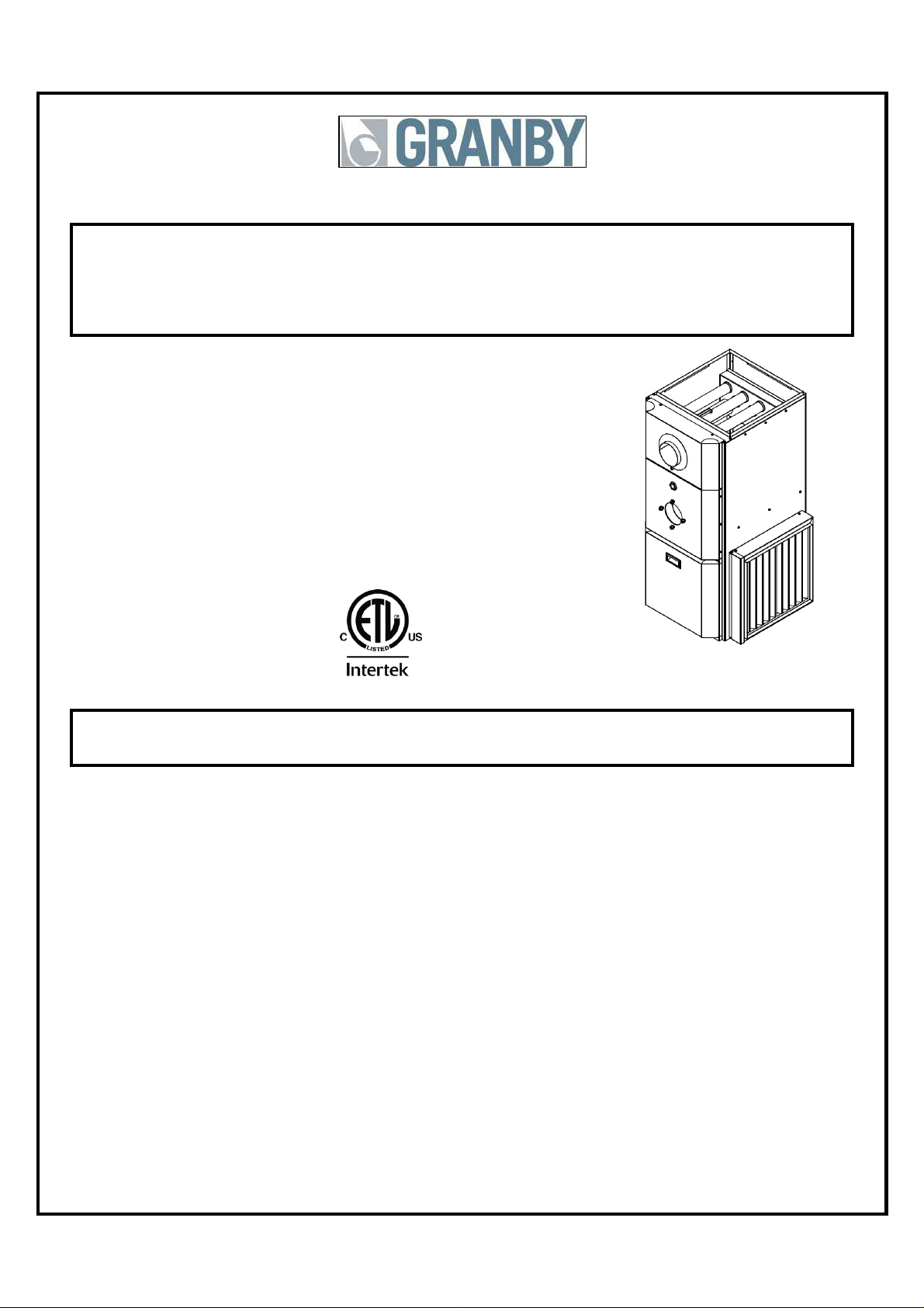
Installation, Operation and
Service Manual
KHM
85% + EFFICIENCY
OIL FIRED HI-BOY FURNACE
KHM-1 / 090
KHM-2 / 140
INSTALLATIONS MUST MEET ALL LOCAL AND FEDERAL
SERIES
CODES THAT MAY DIFFER FROM THIS MANUAL
KHM-1 / 090 Illustration
Please read the manual in its entirety before beginning installation.
This manual must be kept with the furnace for future reference.
GRANBY FURNACES INC.
PO Box 637
12118 Hwy 209
Parrsboro Nova Scotia Canada
B0M 1S0
902-254-2543
www.granbyindustries.com
11-09-2012 G2012-E2 Rev. C
Page 2

TABLE OF
CONTENTS
1.0 IMPORTANT SAFETY ADVICE 2
2.0 PRODUCT INFORMATION
3.0 FURNACE INSTALLATION
4.0 ACCESSORY INSTALLATION
5.0 BURNER INSTALLATION AND SPECIFICATIONS 13
5.1 ASSEMBLY & INSTALLATION OF BURNER 13
5.2 SET BURNER FOR EFFICIENT OPERATION 14
5.3 TECHNICAL INFORMATION 16
6.0 FURNACE OPERATION AND SETTINGS 17
6.1 BLOWER SETTING 17
6.2 FAN TIMER CONTROL BOARD (ST9103 A 1028) 18
6.3 ST9103 A 1028 CONTROL BOARD SEQUENCE 19
6.4 SERVICING – FAN TIMER (ST9103 A 1028) 20
7.0 SERVICE 22
8.0 ELECTRICAL / WIRING DIAGRAMS 25
RIELLO WIRING DIAGRAM 25
BECKETT WIRING DIAGRAM 26
9.0 EXPLODED PARTS VIEW 28
KHM-1 / 90 28
KHM-2 / 140 30
10. START-UP TEST RESULTS 32
3
6
9
1
Page 3
1.0 IMPORTANT SAFETY ADVICE
Please read and understand this manual before installing, operating or servicing the
furnace. To ensure you have a clear understanding of the operating procedures of the
appliance please take the time to read the IMPORTANT SAFETY ADVICE section of this
manual.
WARNINGS
NEVER burn garbage or paper in the unit.
NEVER store combustible material around it.
DO NOT attempt to start burner when excess oil has accumulated, when unit is full of vapour
or when heat exchanger is very hot.
DO NOT use gasoline, crankcase drainings or any oil containing gasoline.
CAUTION
DO NOT START THE BURNER UNTIL ALL FITTINGS, COVERS AND DOORS ARE IN
PLACE. DO NOT TAMPER WITH THE FURNACE OR CONTROLS, CALL A QUALIFIED
BURNER TECHNICIAN. DO NOT STORE OR USE GASOLINE OR OTHER FLAMMABLE
VAPOURS AND LIQUIDS IN THE VICINITY OF THIS UNIT OR ANY OTHER APPLIANCE.
DANGER
Do not use this furnace as a construction heater. Use of this furnace as a construction
heater exposes it to abnormal conditions, contaminated combustion air and lack of air
filtering. Failure to follow this warning can lead to premature furnace failure which
could result in a fire hazard and/or bodily harm and/or materials damages.
IMPORTANT
This manual contains instructional and operational
information for the KHM OIL-FIRED FURNACE. Read
the instructions thoroughly before installing furnace or
starting the burner. Consult local authorities about your
local FIRE SAFETY REGULATIONS. All installations
must be in accordance with local state or provincial
codes. Improper installation will result in voiding of
warranty.
2
Page 4

2.0 PRODUCT INFORMATION
CLEARANCE (minimum) TO COMBUSTIBLES
UPFLOW POSITION
Top & Sides of Supply Plenum 1” (25 mm)
Front (Maintenance) 24” (610 mm)
Rear 0” (0 mm)
First Side 0” (0 mm)
Other Side 0” (0 mm)
Flue Pipe 9” (229 mm)
Floor Combustible
DOWNFLOW POSITION
Top 2” (51 mm)
Bottom and Sides - Plenum 1” (25 mm)
Rear 0” (0 mm)
First Side 0” (0 mm)
Other Side 0” (0 mm)
Front (Maintenance) 24” (610 mm)
Flue Pipe 9” (229 mm)
Floor (with Down flow base) Combustible
HORIZONTAL POSITION
Top 2” (51 mm)
Bottom and Sides - Plenum 1” (25 mm)
Rear 1” (25 mm)
First Side 1” (25 mm)
Other Side 1” (25 mm)
Front (Maintenance) 24” (610 mm)
Flue Pipe 9” (229 mm)
Floor 2” (51 mm)
DRAFT PRESSURE
Breech draft pressure -0.01” wc minimum
AIR/BLOWER DATA
External static – Non A/C 0.2” wc
External static – A/C 0.5” wc
Maximum cooling 3.0 tons… KHM-1 / 090
5.0 tons… KHM-2 /140
Maximum air temperature rise See page 16 and 33
High Limit, max design outlet temp 185°F
Thermostat anticipator 0.2 amps
MOTOR/BLOWER
KHM-1 / 090: 1/2 hp 4 Speed / G10-8 DD or 1/2 hp ECM / G10-8
KHM-2 / 140: 3/4 hp 4 Speed / GT12-10DD or 3/4 hp ECM / GT12-10
3
Page 5
FAN/HIGH LIMIT CONTROL
Honeywell ST9103 Fan Center & Thermo-Disk (7” stem)
DIMENSIONS (KHM-1 / 090)
Depth 26” (660 mm)
Height 46 1/4” (1175 mm)
Width 21 7/16” (545 mm)
DIMENSIONS (KHM-2 / 140)
Depth 30” (762 mm)
Height 49 7/8” (1267 mm)
Width 21 7/16” (545 mm)
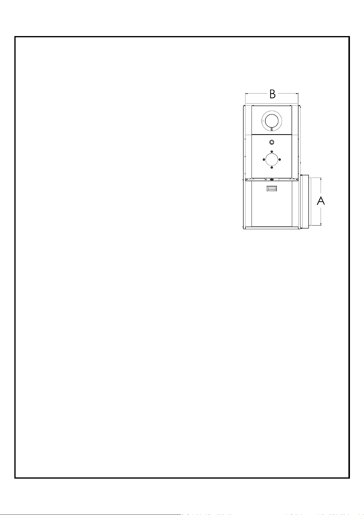
PLENUM DIMENSIONS (KHM-1 / 090)
Cold air return (A) 18” x 18” (457 x 457 mm)
Hot air supply (B) 20” x 20” (508 x 508 mm)
PLENUM DIMENSIONS (KHM-2 / 140)
Cold air return (A) 23” x 18” (584 x 457 mm)
Hot air supply (B) 24” x 20” (610 x 508 mm)
AIR FILTERS
KHM-1 / 090 20” x 20” x 2” non-pleated UL approved
KHM-2 / 140 25” x 20” x 2” non-pleated UL approved
A/C COIL LOCATION
Minimum height above the heat exchanger 6” (152 mm)
See A/C Coil Manufactures Requirements
SMOKE-PIPE CONNECTION
5” Chimney or direct vent DVS Granby kit
CLEANOUTS
Front Cover & Burner Opening
THERMOSTAT
Any thermostat
FUEL
Not heavier than No. 2 furnace oil.
ELECTRICAL – 120 Volts, 60 Hz
Canada Less than 12 amps.
USA 13.3 amps, circuit protection 20 amps.
4
Page 6
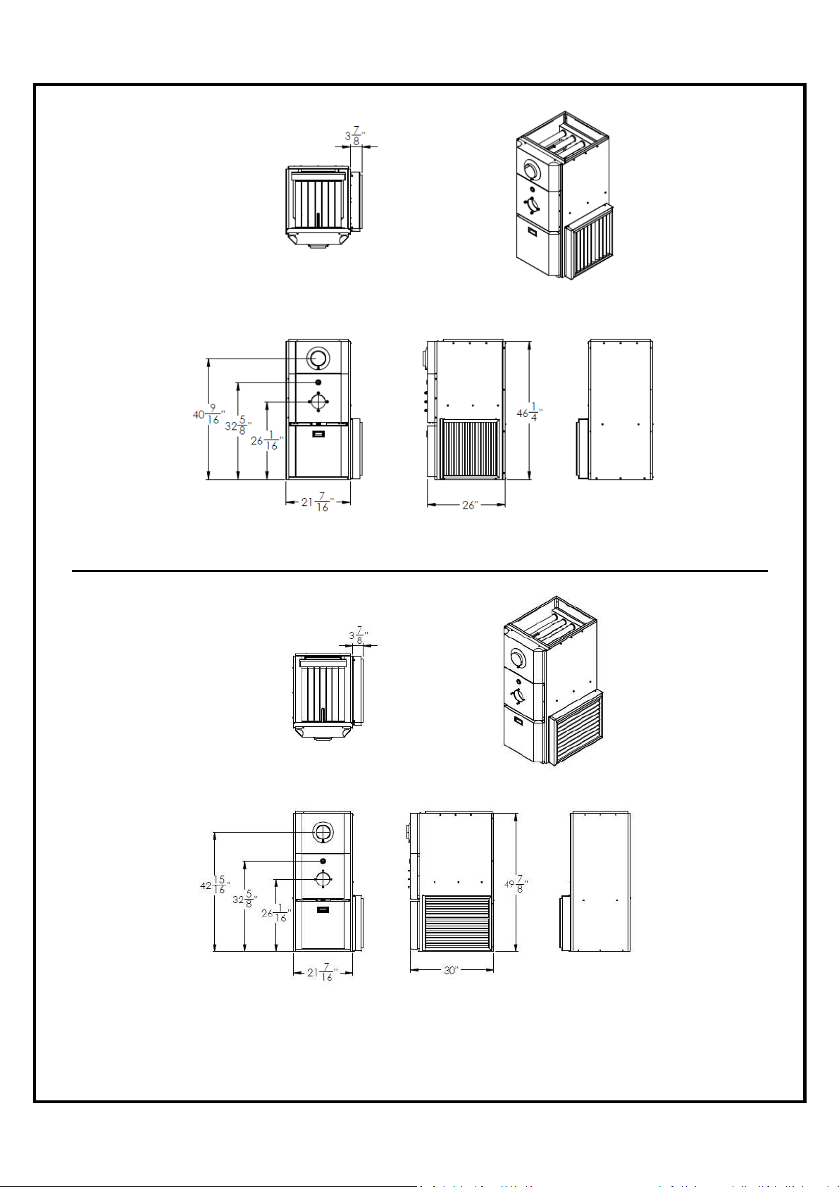
KHM-1 / 090 - DIMENSIONS
Dimensions are in inches
KHM-2 / 140 - DIMENSIONS
Dimensions are in inches
5
Page 7
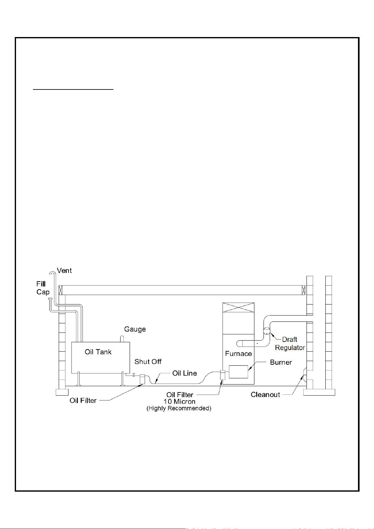
3.0 FURNACE INSTALLATION
OIL TANK & PIPING
Tank installation must conform to local requirements.
Install according to the applicable code such as CSA B139 and NFPA 31. Minimize the
number of connections in suction line and make all connections as tight as possible. Use a
pipe joint compound suitable for oil on all pipe threads. To reduce possibility of air leaks,
tighten stem packing gland nut on any valves installed in the suction line. Also, be sure the oil
filter is tight, as filter gaskets often shrink. Check for kinks in the oil lines as well as for
possible air pockets and for loose connections. Two filters as shown below are recommended.
Optional tank gauge protectors and outlet protectors are available at your local dealer.
ONE PIPE SYSTEM Where the tank is above the burner and when the oil flows by
TWO PIPES SYSTEM When a single line is unsuitable, use a double line system or see
gravity to the oil pump, a single-stage fuel unit with a single oil line
to the pump may be used.
your dealer for special oil line fittings. Install by-pass plug on burner
fuel unit as specified in the burner manual.
Oil Tank and Piping
6
Page 8
PLACEMENT & VENTING
Furnace installation shall conform to the required installation code for oil-fired equipment (USA:
NFPA 31, Canada: CSA B139).
FLOOR SUPPORT COMBUSTIBLE – If required, support furnace on five (5) concrete
blocks. Make sure the center of the furnace base is supported.
Approved for installation on combustible floors in the upflow position and
downflow position (with the optional sub-base). Not approved for
installation on combustible floor in horizontal applications. For horizontal
applications, use railing type support (not supplied) to keep the furnace
in position. Make sure that all clearances are respected.
CHIMNEY/VENT Connect the furnace to a chimney/vent system of size and condition
required by the NFPA 31 (USA) or CSA B139 (Canada) code. Furnace
is approved for factory built chimney type “L” vents. Breech is certified
for 5” vent pipe. Keep vent/flue pipe as short as possible with a
minimum upward slope of ¼’’ per foot. Vent/flue pipes MUST NOT pass
through a ceiling. Maximum flue gas temperature is 575°F.
CONDENSATION If you have condensation in your chimney, make sure that the
chimney size is according to the tables in CSA B139 / NFPA 31.
The temperature at the entrance of the chimney can be increased
by insulating the flue-pipe between the furnace and the chimney
base. If this is not sufficient, consider cutting or removing some
flue baffles in the furnace. BE AWARE THAT REMOVING BAFFLES
REDUCES THE UNIT EFFICIENCY AND A MODIFIED UNIT IS NO
LONGER ENERGY STAR APPROVED.
COMBUSTION &
Install openings and ductwork to the furnace room providing fresh
VENTILATION AIR outside combustion and circulation air for cooling the furnace casing, as
installation code requires (USA NFPA 31, Canada CSA B139). If
installed in a closed room, provide two free air ventilation openings of at
least 8” x 12” (96 sq. in.) free flow area near ceiling and floor. Oil burners
must have sufficient air to allow vent systems to operate properly.
DRAFT Use approved draft control supplied for 5” pipe. Set specified draft
minimum pressure of -0.01” wc.
ELECTRICAL Wire according to the National Electrical Code (Canadian Electrical
Code in Canada) or local codes. Use a separately fused #12 electrical
line directly from the service panel to the furnace junction box. Install a
manual shut-off switch at the door or stairway to furnace room so
furnace can be shut off remotely.
CLEARANCES Before placing unit, review installation clearances as shown on furnace
operating decal or section PRODUCT INFORMATIONS.
LOCATION Install the furnace close to chimney and central to ductwork.
7
Page 9
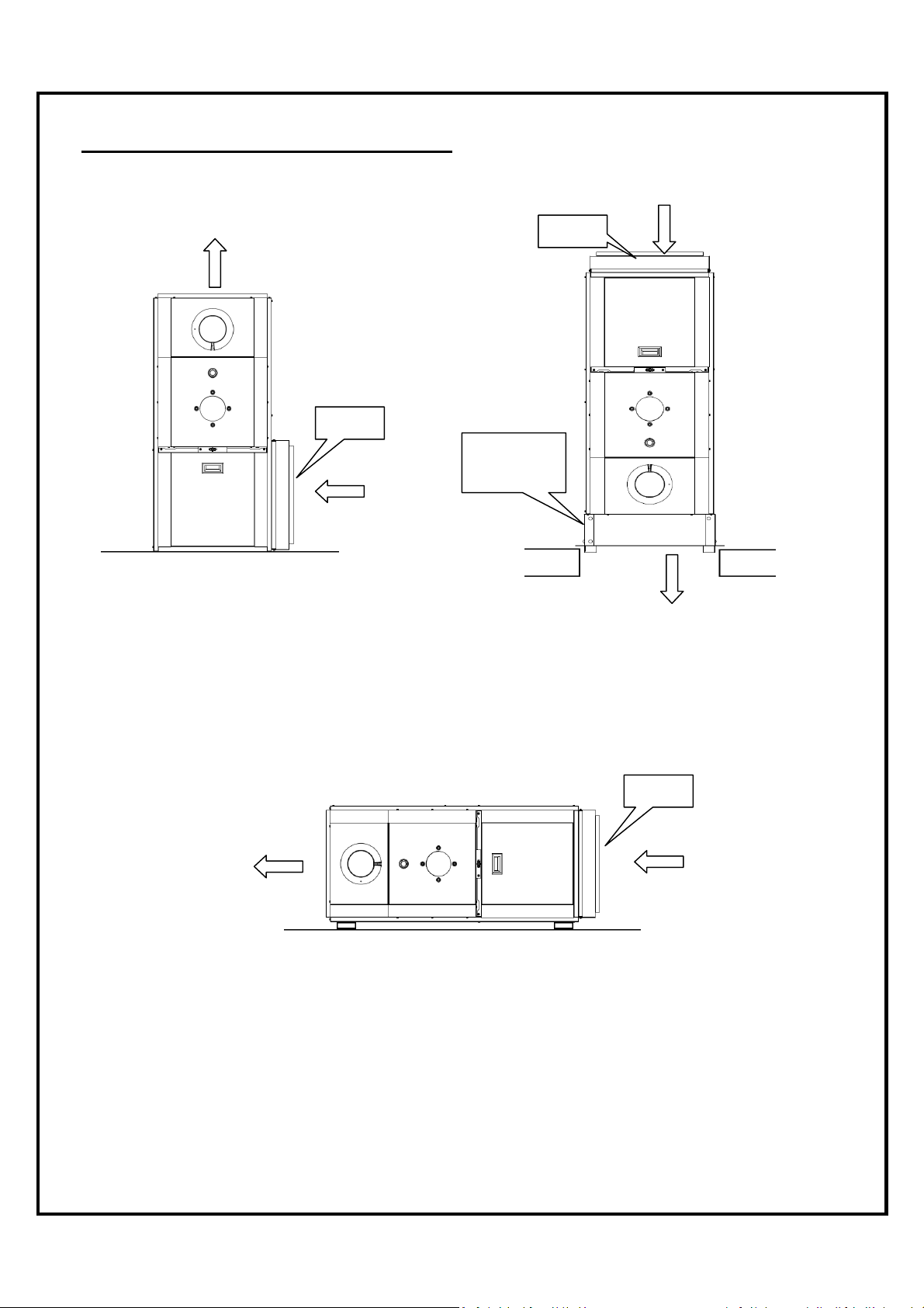
WARM AIR
WARM AIR
Filter
Filter
Filter
used to ensure these clearances.
MULTI-POSITION CONFIGURATIONS
UPFLOW INSTALLATION DOWNFLOW INSTALLATION
AIR RETURN
The return air opening can be located
on left side or on the right side of the
unit. After installing the filter rack
supplied with the unit we recommend
installing the blower door before
handling the unit.
HORIZONTAL INSTALLATION
Downflow
Sub-base
WARM AIR
When the unit is installed in downflow
configuration on a combustible floor, the
clearance from combustible material must be
respected. The downflow sub-base
CAB-A0-0045-00 (for KHM-1/090) or
CAB-A0-0046-00 (for KHM-2/140) can be
AIR RETURN
When the unit is installed in the horizontal configuration on a combustible floor with a choice of
right or left air outlet, the clearance of (2’’) from combustible material must be taken into
consideration.
The burner must always be installed facing upwards regardless of the
For complete clearance information to combustibles, see PRODUCT
configuration installation.
INFORMATION, page 3.
AIR RETURN
8
Page 10
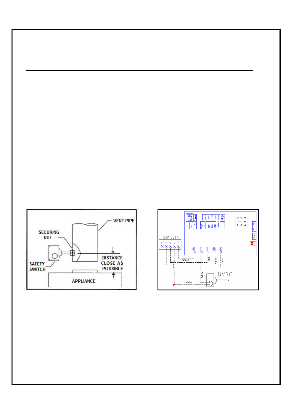
4.0 ACCESSORY INSTALLATION
BLOCKED VENT SWITCH (BVSO) FOR CANADIAN APPLICATION ONLY
Oil-fired appliances installed in Canada require a blocked vent switch system when installed on
a chimney. A safety switch is included with the furnace to perform this function. It is the
installer’s responsibility to install the switch in accordance with the instructions provided. Not
applicable for Direct Vent systems. Field Controls Model: WMO-1 (Manual Reset)
Switch Operation
Blocked vent switches are flue gas safety devices for detecting spillage of flue gases due to a
blocked flue or inadequate draft. After detecting a problem, the switch de-energizes the
system’s burner control.
NEVER reset the switch unless the cause of the blockage has been corrected.
Installation (Figure 1)
1) Drill a 5/8” hole in to the flue vent pipe near the appliance breech connection.
2) This hole must be before the draft regulator, vertically or horizontally.
3) Remove one of the securing nuts from the threaded tube of the safety switch.
4) Tighten the other securing nut onto the pipe as far as possible.
5) Insert the threaded tube end into the pierced hole of the flue vent pipe.
6) Install the securing nut on the safety switch tube, which protrudes into the flue vent pipe.
Tighten the nut securely.
Figure 1-
Illustration from the instruction
Figure 2- BVSO wiring diagram
manual of Field Controls
Wiring Instructions (BVSO)
Caution: Disconnect the electrical power when wiring the unit.
Wire the blocked vent switch in accordance with The National Electrical Code and applicable
local codes. Wire the safety switch (BVSO) in series with the thermostat and the fan timer
relay control (Figure 2).
9
Page 11
System Test Procedure (BVSO)
1) With the power re-established, block the chimney or vent pipe downstream of the switch.
2) Adjust the thermostat to call for heat.
3) Once the heating system has started the blocked vent switch should shut down the burner
within 10 minutes or sooner.
4) Once the system has cooled, the blocked vent switch can manually be reset.
5) This procedure should be tested a second time.
6) After testing the blocked vent switch the chimney should be cleared of obstruction and the
heating system should be tested over a long run cycle.
If the block vent switch shuts down the system, check to ensure there is enough draft in the
chimney and venting pipes.
AIR CONDITIONING
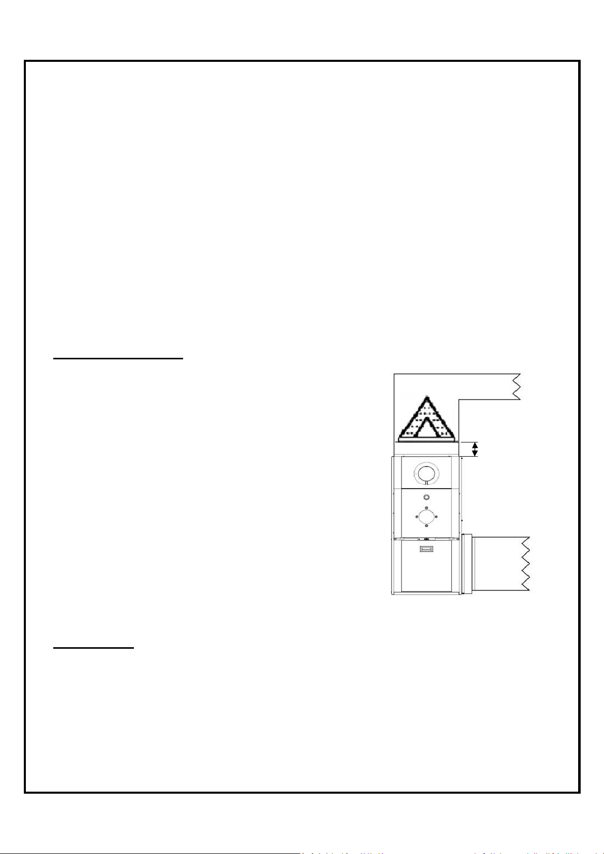
An air conditioning coil may be installed on the supply side
only. Coils installed on the return side will cause
condensation on the heat exchanger; this will shorten the heat
exchanger life and may cause products of combustion to enter
the house. Wire as per wiring label and diagram. Height of
the coil above the unit supply shall be at least 4” (102
mm).
4 inch
minimum
See A/C coil Manufacturers Requirements.
To check the AC coil total air flow resistance,
see procedure at page 33.
HUMIDIFIER
If a humidifier is installed ensure that no water can drip or run from it into the furnace. This
would cause deterioration and void the furnace warranty.
10
Page 12
rack
Spacer
holder
door
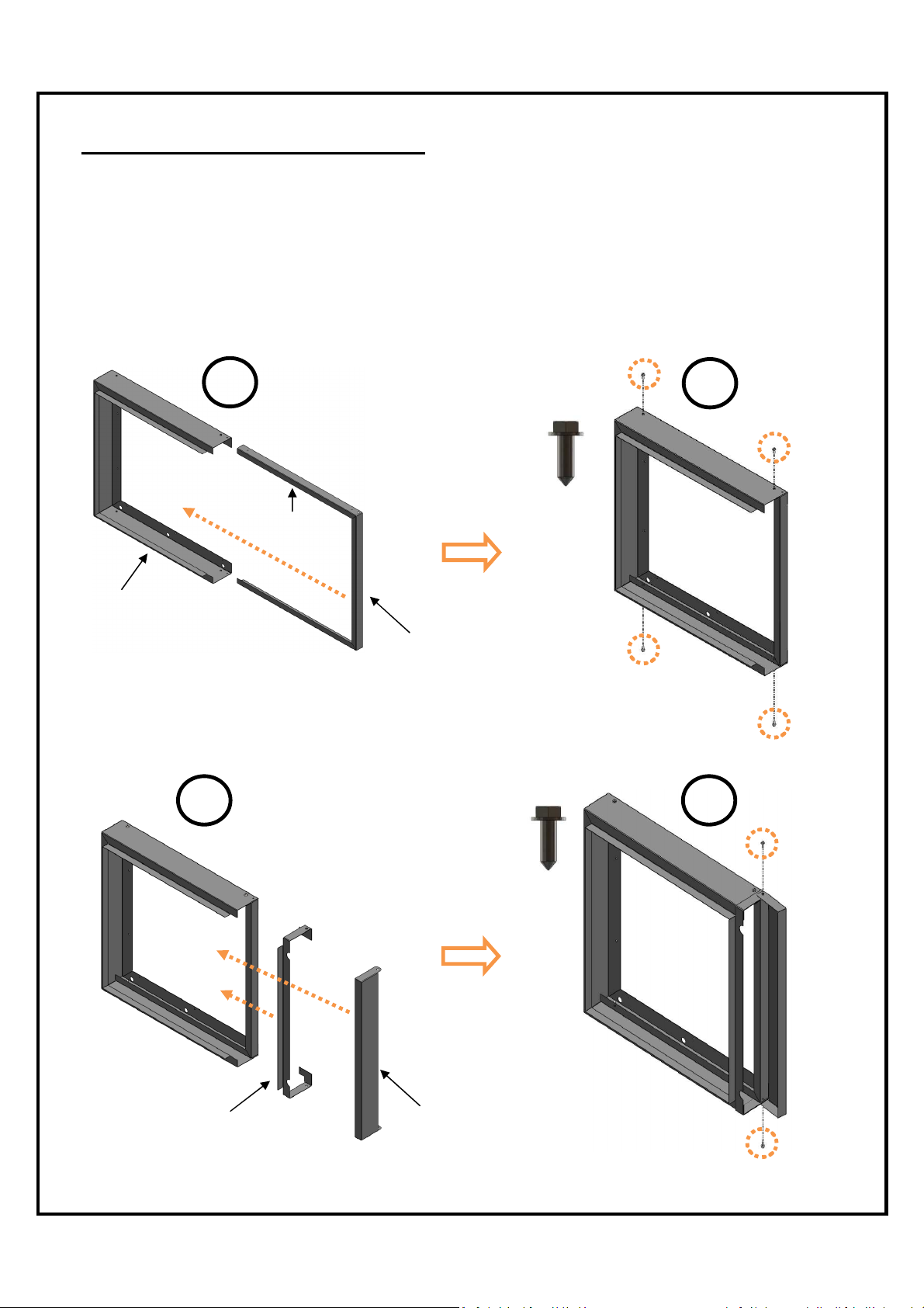
AIR FILTER RACK INSTALLATION
The air filter rack is shipped uninstalled inside the furnace. This way the owner can install it in
the position that he wants. There are 3 possible locations to install the air filter rack which are:
bottom left side, bottom right side and under the furnace. Follow the instructions below to
install the air filter support properly.
Step 1: Slide air filter spacer inside the outside filter rack.
Step 2: Screw in the 4 screws to hold these two parts together.
1
2
4 X
Bend must be
facing out
Outside filter
Air filter
Step 3: Slide filter holder door and filter door.
Step 4: Use the 2 remaining screws to maintain the filter door in place.
3
2 X
4
Door
Filter
11
Page 13
7
5
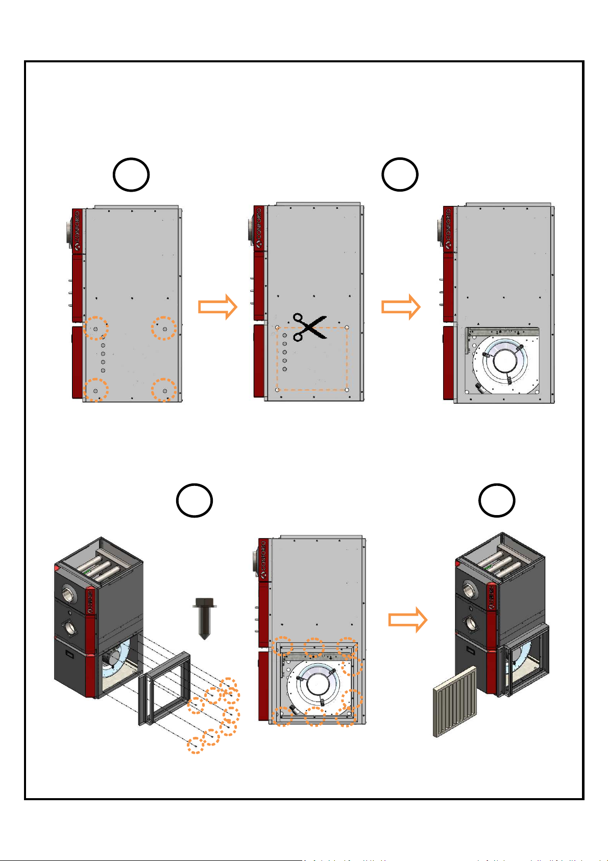
Step 5: Remove the 4 knockouts on the panel (left side, right side or base panel) where you
want to install the air filter
Step 6: Cut the panel between the 4 knockouts.
6
Step 7: Using 8 screws ,install the air filter rack on the furnace.
Step 8: Slide the air filter inside the air filter rack
8 X
8
12
Page 14
5.0 BURNER INSTALLATION AND SPECIFICATIONS
5.1 ASSEMBLY & INSTALLATION OF BURNER
ASSEMBLE Check burner model is correct for furnace rating required. Assemble as
per burner manufacturer’s instructions.
SELECT NOZZLE Select oil input, nozzle and burner configuration as shown on furnace
operating decal.
INSTALL NOZZLE Install selected nozzle, check for clean seating and tighten in nozzle
adaptor.
ELECTRODES See burner manufacturer’s instructions for correct setting.
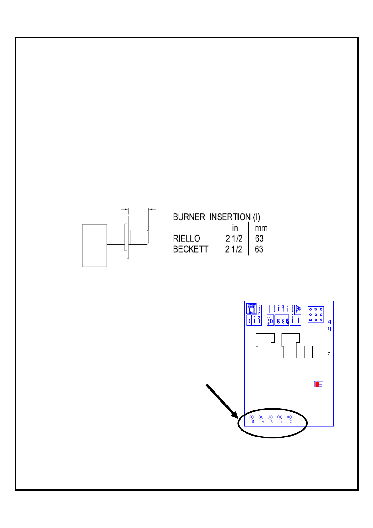
INSERTION See figure below.
LENGTH
.
PUMP BY-PASS For one pipe system factory setting (no
PLUG plug).
WIRING Refer to wiring diagram for correct
burner connections (see page 25 or 26).
THERMOSTAT Connect the thermostat wires to the fan
timer control board (ST9103).
13
Page 15
5.2 SET BURNER FOR EFFICIENT OPERATION
BURNER SETTINGS Use burner settings in the table on page 16 or operating decal as a
guide to set burner, particularly for nozzle change. Those settings
are only starting points for the adjustments and are not meant as
final settings.
On Beckett AFG burner, make sure the correct retention head and
static disk are installed on the burner for the desired firing rate. The
head is held in place by two (2) screws at the end of the burner blast
tube. In the burner model in the table of page 16, the head is always
after the AFG designation and the static disk after the head. For
example, the AFG L2 3 3/8 means an AFG chassis burner with a L2
head and a static disk of 3 3/8.
PUMP PRESSURE Refer to the table on page 16 or operating decal.
AIR SETTING Use air settings on page 16 as a guide to set air adjustment. Those
settings are only starting points for the adjustments and are not
meant as final settings.
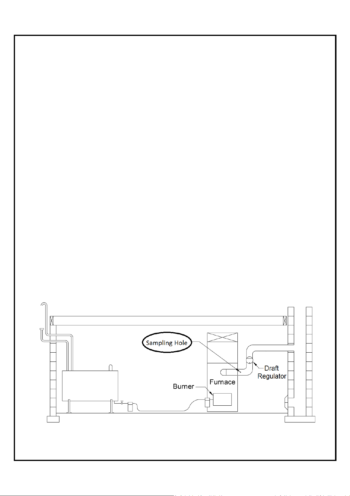
DRAFT REGULATOR The draft regulator should be installed at least three (3) flue pipe
diameters from breeching or elbow of the furnace.
SAMPLING HOLE On smoke/vent pipe, drill a 3/8” round opening. The hole should be at
least two (2) flue pipe diameter from breeching or elbow of the furnace.
14
Page 16
DRAFT PRESSURE Using an accurate draft meter; adjust the draft control to obtain - 0.01”
wc minimum draft pressure at the breech sampling hole. The draft
regulator’s adjustments should be made after furnace has been
running under heating mode for at least five (5) minutes minimum.
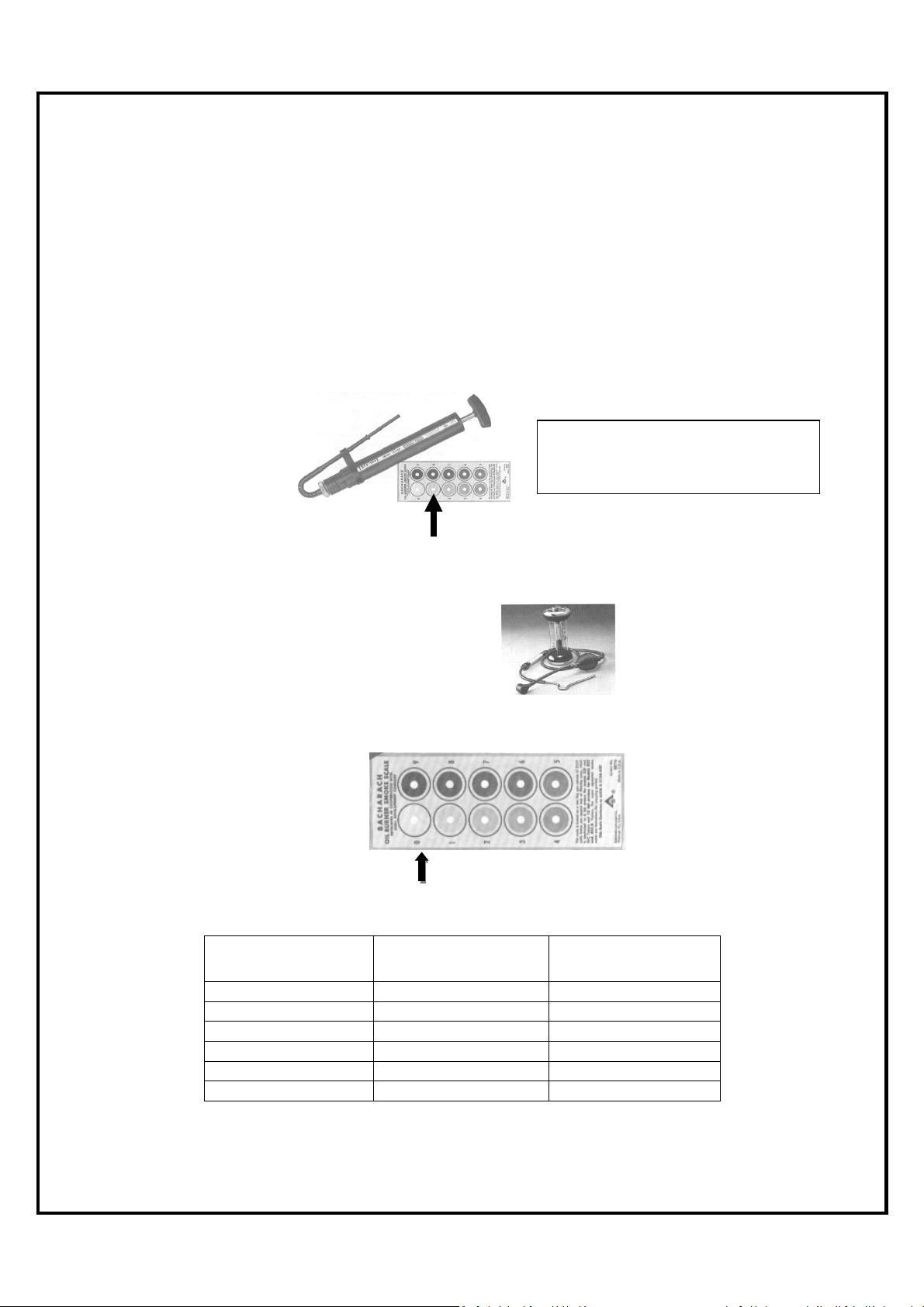
COMBUSTION TEST All your tests must be done with the burner cover on (Riello)
COMBUSTION After 10 minutes of normal operation, take a smoke test and adjust
SETTING/ the burner to obtain a reading of “1” on the smoke scale. Take a CO2
EFFICIENCY test and note the result.
To reach the maximum smoke test
value, a 10 full slow steady pump
action is required.
Open the air band adjustment on the burner to reduce your CO2
lecture by 1%.
To reach the maximum
CO2 test value, a 18 full
slow steady pump action is
required.
You now have a perfect “slight trace” of smoke.
Relation between % of CO2 and O
2
CO
(%) O
2
13.5 2.6 15.0
13.0 3.3 20.0
12.5 4.0 25.0
12.0 4.6 30.0
11.5 5.3 35.0
11.0 6.0 40.0
(%) Excess Air (%)
2
15
Page 17
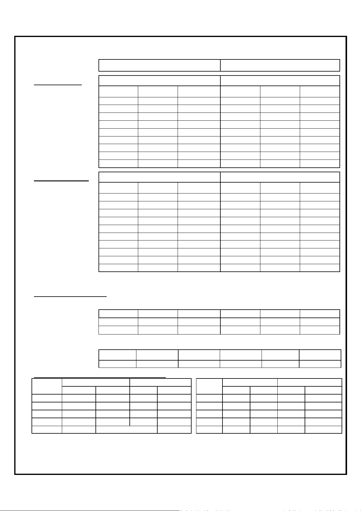
5.3 TECHNICAL INFORMATION
Riello Burner
Ene
rgy Star Approved
03
03
03
05
05
05
CO
2
(%)
LO
875
850 1150
1050
LO 775 750 1060
1010
KHM Series
KHM-1 / 090 KHM-2 / 140
F3 F5
Unit Model
Firing Rate (USGPH)
Input (BTU/h)
Output (BTU/h)
Nozzle
Pump Pressure (psi)
Turbulator Setting
Air Gate Adjustment
AFUE (%)
KHM-E1-*067-
03
0.55 0.65 0.75 0.90 1.05 1.15
77,000 91,000 105,000 126,000 147,000 161,000
67,000 79,000 91,000 109,000 126,000 139,000
0.40 70A 0.60 70W 0.65 70W 0.75 80W 0.85 70W 1.00 70W
190 145 145 145 165 145
0 0 0 0 1 2
1.75 2 2.35 2 2.25 2.25
YES YES YES YES YES YES
86.50 86.80 86.30 87.50 86.60 86.90
KHM-E1-*079-
03
KHM-E1-*091-
03
KHM-E3-*109-
05
KHM-E3-*127-
05
KHM-E3-*139-
05
Beckett Burner AFG L2 3-3/8 AFG F3 2-3/4
Unit Model
KHM-G2-*066-
Firing Rate (USGPH) 0.55 0.65 0.75 0.85 1.00 1.10
Input (BTU/h) 77,000 91,000 105,000 119,000 140,000 154,000
Output (BTU/h) 66,000 78,000 90,000 102,000 119,000 132,000
Nozzle 0.50 60W 0.60 60W 0.65 60W 0.75 70B 0.85 70B 1.00 70B
Low Firing Rate Baffle YES YES YES YES YES YES
Pump Pressure (psi) 145 145 145 145 145 145
Air Band (Gross) 1 1 1 1 2 2
Air Shutter (Fine) 4 6,5 8 7 6 10
Energy Star Approved YES YES YES YES YES YES
AFUE (%)
86.80 86.60 86.00 86.70 86.50 86.40
12.5 13.5 13.7 12.5 13.5 13.5
General Information
PSC motor info
Temperature Rise (°F) 40 – 70 40 – 70 50 – 80 40 – 70 40 – 70 50 – 05
Blower Speed
Blower Speed
Energy Star ECM motor (0.2’’ wc to 0.5’’ wc static pressure)
Temperature Rise (°F) 50-80 55-85 60-85 52-85 55-85 55-85
Blower Speed M-LOW M-LOW MEDIUM M-LOW MEDIUM M-HIGH
(0.2’’ wc)
(0.5” wc)
M-LOW M-HIGH M-HIGH M-LOW M-HIGH M-HIGH
M-HIGH M-HIGH HIGH M-HIGH HIGH HIGH
KHM-G2-*078-
KHM-G2-*090-
KLHMG2-*102-
KHM-G2-*119-
KHM-G2-*132-
Static Pressure at 0.2'' WC / 0.5'' WC
Blower PSC 1/2 hp PSC 3/4 hp
Speed 0.2" wc 0.5" wc 0.2" wc 0.5" wc
MHI 1250 1170 1940 1875
MED --- --- --- --MLO 1100 1075 1710 1650
HI 1375 1275 2120 2030
(*) In the Unit Model number, is specific information of the product for administration only
Blower ECM 1/2 hp ECM 3/4 hp
Speed 0.2" wc 0.5" wc 0.2" wc 0.5" wc
HI 1300 1230 2000 1910
MHI 1225 1160 1900 1835
MED 1140 1050 1690 1660
MLO 1025 980 1610 1575
16
Page 18
6.0 FURNACE OPERATION AND SETTINGS
SHUTTING FURNACE DOWN
POWER OFF Turn off main power breaker or disconnect.
FUEL OFF Shut off manual fuel supply valve.
Always keep manual fuel supply valve shut off if the burner is shut down for an extended
period of time.
RESTARTING FURNACE
Follow this procedure before restarting a unit that has been shut down for an extended period
of time.
INSPECTION Have the furnace/system serviced and inspected by a qualified technician.
FUEL Turn on fuel supply and check that there are no leaks.
POWER Turn on power and check that the furnace starts and operates as usual.
OPERATION If the furnace/system fails to operate or operates in an unusual manner, call
your service technician. If the burner fails to operate at any time, call a
qualified burner technician.
6.1 BLOWER SETTING
Ensure power is off when adjusting blower setting. For heating, use the blower speeds
shown on the furnace specifications to give a temperature rise according to tables on page 16.
The Lo blower speed can be used for air circulation when neither heating nor cooling are
required. Set blower speeds to match the installation requirements.
THERMOSTAT ANTICIPATOR SETTING
Adjust to thermostat manufacturer’s instruction.
FAN & LIMIT CONTROL
Limit 185°F (Factory set)
Fan On 45 seconds after burner stats
Fan Off Adjustable on fan control board (see page18)
17
Page 19
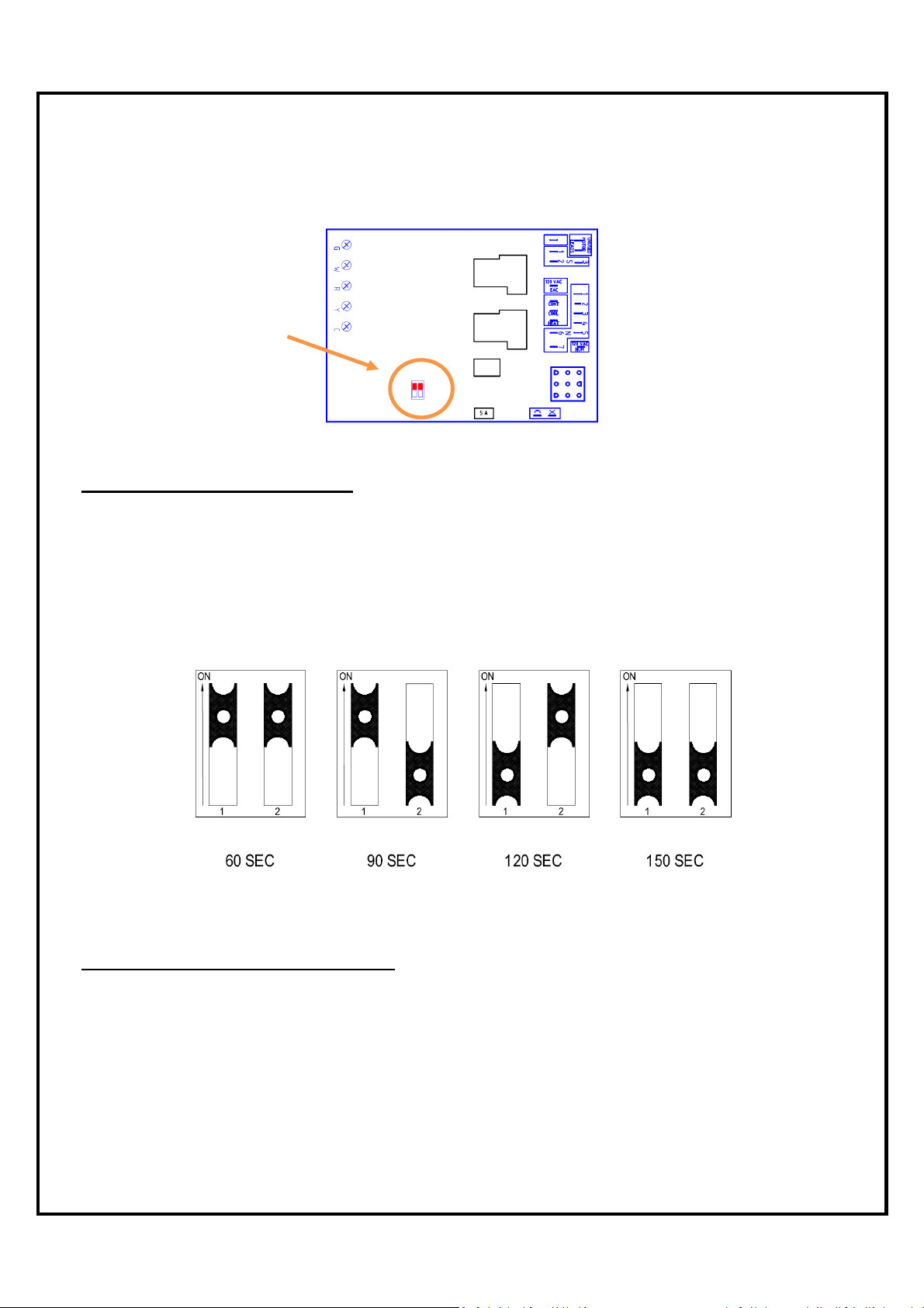
6.2 FAN TIMER CONTROL BOARD (ST9103A 1028)
o “FAN OFF” Dip Switches adjustment
Dip Switches
COMFORT ADJUSTMENTS
o Outlet air consistently too warm or too cold - change the blower motor speed to give the
specified air temperature rise.
o Outlet air gets too warm and burner shuts down - increase air by changing the blower
motor speed to give the specified temperature rise.
o Outlet air is too cold or too warm at the end of the heating cycle after the burner has turned
off - adjust the “FAN OFF” dip switch on electronic fan center. Refer to the next figure.
“FAN OFF” Dip Switch
OFF CYCLE AIR CIRCULATION
LOW SPEED All KHM models have the low speed switch for optional constant air
circulation during the furnace off cycle.
“FAN ON” When “FAN ON” is selected on the thermostat, the blower will run constantly
at the blower speed selected on the heating terminal. This is the equivalent of
jumping terminals R and G on the ST9103 board.
18
Page 20
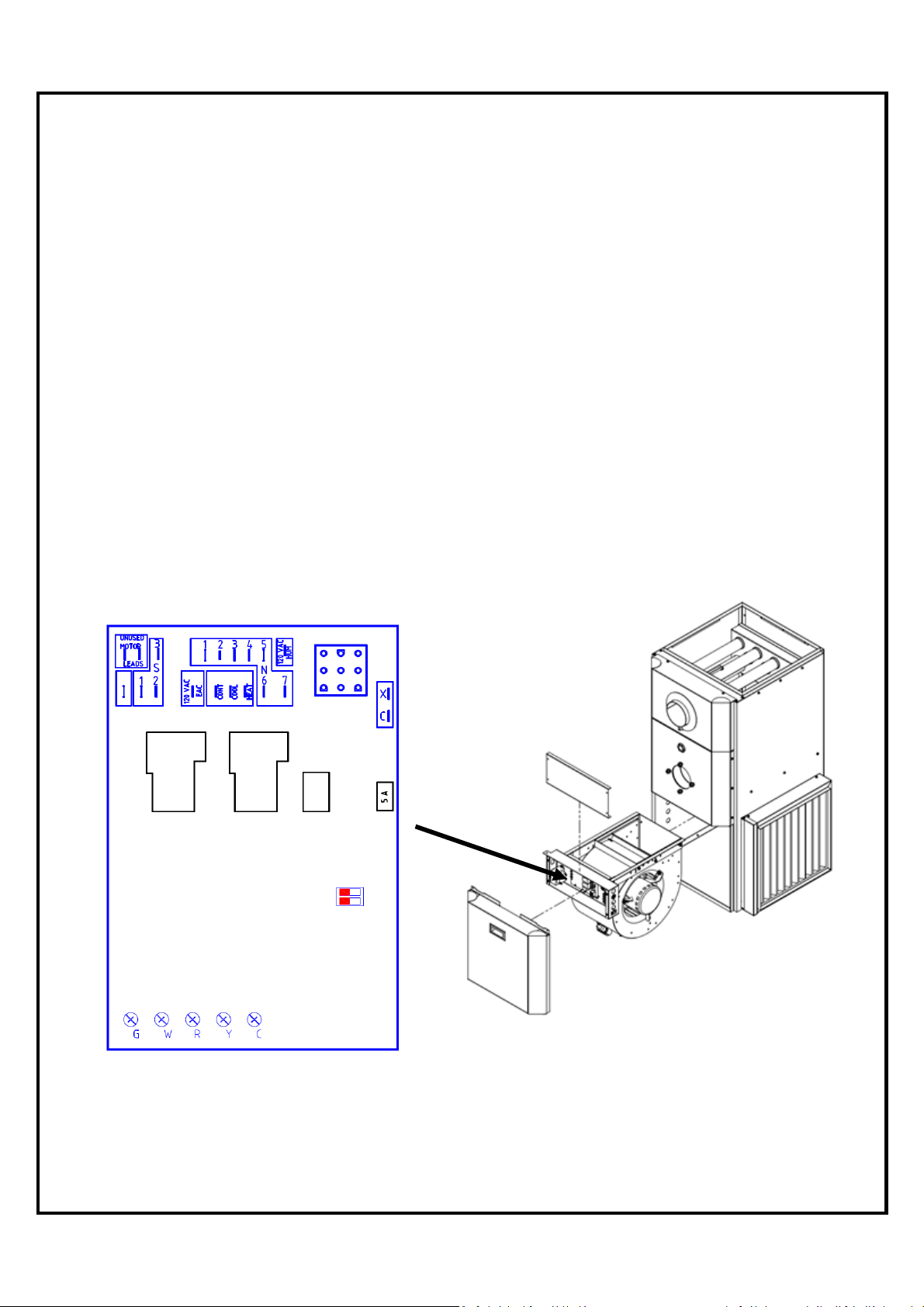
6.3 ST9103A 1028 CONTROL BOARD SEQUENCE
ST9103 Heating Sequence
1) Thermostat calls for Heat.
2) Burner starts
3) Blower starts after 45 seconds
4) Burner shuts down after call for heat is satisfied
5) Blower stops according to adjusted (FAN OFF) Dip switch selection
ST9103 Cooling Sequence
1) Thermostat calls for cooling
2) Blower starts immediately
3) Cooling unit starts
4) Blower stops immediately after cooling demand is satisfied
5) Cooling unit stops
Honeywell ST9103A 1028 Electronic Board
19
Page 21
Step
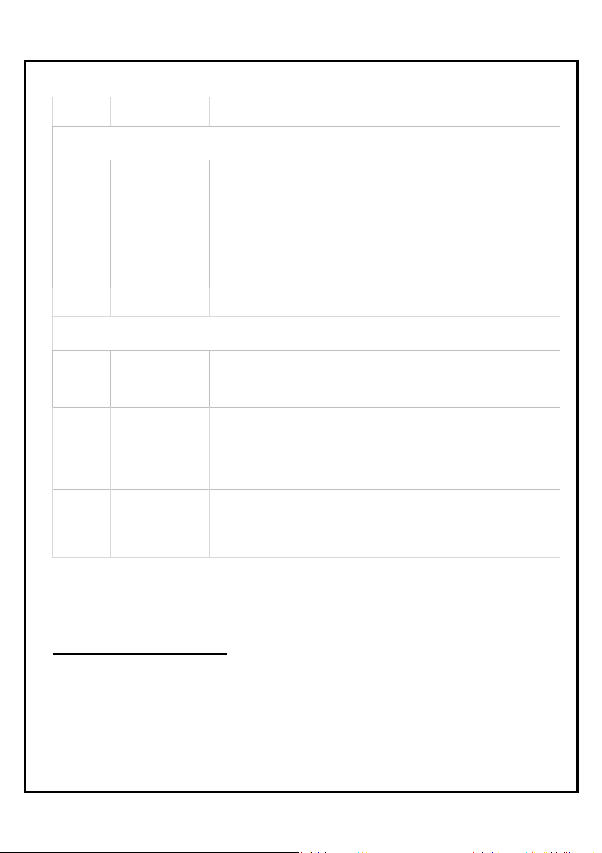
Possible Cause
Check
-
out procedure
Corrective action
on electronic fan control
Check breaker main power switch
electronic fan control.
Check for bad connection
Change Transformer
Yes
- Move to next step
Yes
- Move to next step
Warning: Make sure the quick connect cable is fully inserted on the board
Yes
- Move to step # 5
Failure on the limit control circuit
Temperature too high
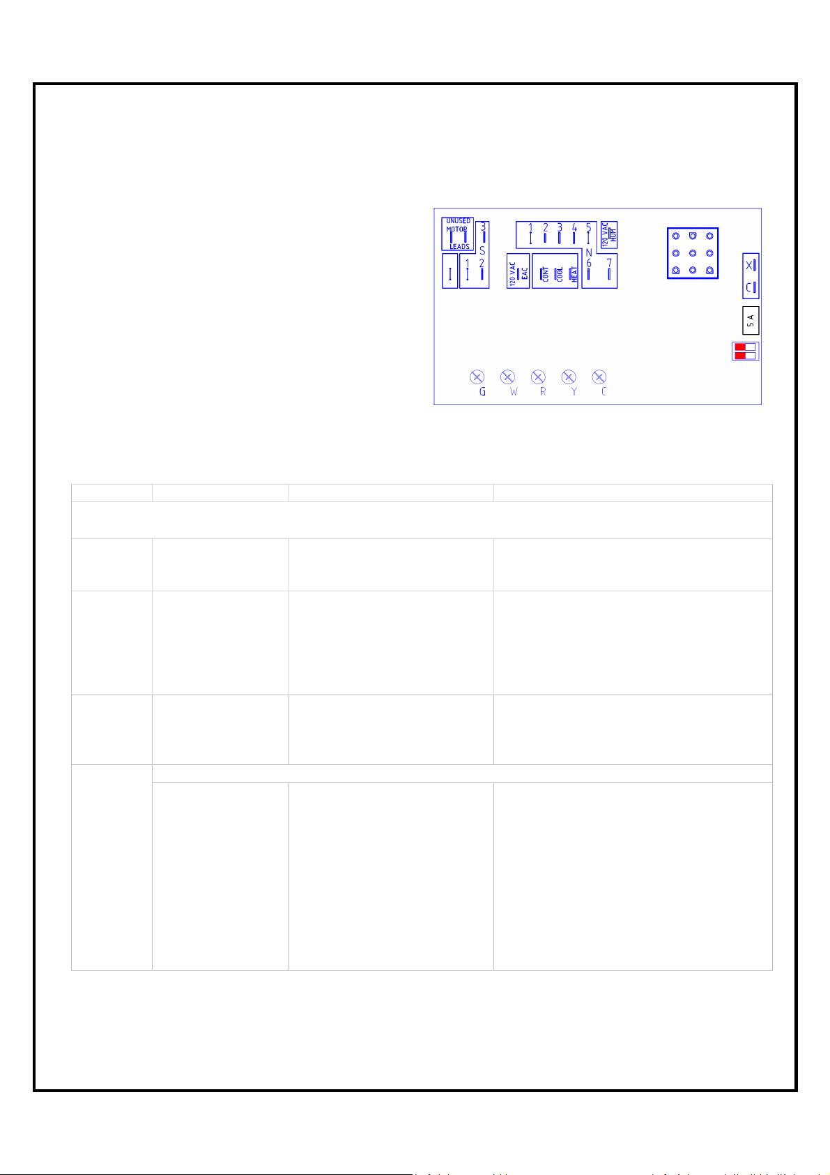
6.4 SERVICING - FAN TIMER ST9103A 1028
Trouble shooting the electronic board ST 9103
Before trouble shooting
the board,
check for the 5 amp. fuse
For accurate trouble shooting, follow
step by step the Trouble Shooting Chart.
1 Incoming supply
2 Transformer
3
4
Electronic Fan
control
Limit Control
No Heat
Check for 120 Volts
between terminal S2 and 3
Check for 120 Volts between
terminal S3 and 4 on
Check for 24 Volts between
terminal X and C on
electronic fan control
Check for 24 Volts between
R and C
Check for 24 Volts between
terminal W and C
Check for 120 Volts on each
terminal of the two limits
Check for 120 Volts coming
from the main plug-in of the
electronic fan control to the
limit control
Check for 120 Volts coming
out of the limit control
Yes - Move to next step
No -
Yes - Move to next step
No -
Yes - Move to next step
No -
No - Change the electronic board
No - Check thermostat and wiring
Yes - Move to step # 5
No - Move to next step
Yes - Move to next step
No - Change the electronic fan control
No -
.
. Bad limit control
20
Page 22
Yes
- Move to next s
tep
Blower
Step Possible Cause
5 A
5 B
Riello burner
application
Beckett Burner
application
Check-out procedure Corrective action
No Heat
Check for 120 Volts on the
black wire, contact (COM)
on the Riello burner relay
kit.
Check if oil primary control
is on reset
Check for continuity
between the two wires
yellow and violet on the
Riello burner relay kit
Check for 120 Volts on the
contact (No) of the Riello
burner relay kit
Check for 120 volts on the
orange wire coming to the
burner (L)
Check for 120 Volts on the
black wire terminal strip (mid
terminal)
Check if oil primary control
is on Reset
Check for continuity
between the two wires black
and gray (TT) on primary
control
Yes - Move to next step
No - Back to step # 4 or check for bad
connection
Yes - Press reset button
No - Move to the next step
Yes - Move to next step
No - Change the electronic fan control
Yes - Move to next step
No - Change the Riello burner relay kit
Yes - Failure on the burner
No - Change the electronic fan control
No - Back to step # 4 or check bad
connection
Yes - Press reset button
No - Move to the next step
Yes - Move to next step
No - Change the electronic fan control
6
.
Low speed
Check if the
constant low
speed switch is
ON
Check for 120 Volts coming
from the electronic fan
control to the primary control
(black wire)
Check for 120 Volts coming
from the primary control
(orange wire) to the
transformer, motor and the
electronic board
Check for 120 Volts at the
''CONT'' terminal on the
electronic fan control
Check for 120 Volts on both
side of the constant low
speed switch
Yes - Move to next step
No - Change the electronic board
Yes - Failure on the burner
No - Change the primary control
Yes - Move to next step
No - Change the electronic fan control
Yes - Check ''LOW'' speed on the
blower motor
No - Change the switch
21
Page 23
Compressor ON
Humidifier failure
Step Possible Cause Check-out procedure Corrective action
No Cooling
7
Step Possible Cause Check-out procedure Corrective action
Blower .
High speed
Check for 24 Volts between
G and C on electronic fan
control
Check for 120 Volts at the
''COOL'' terminal of the
electronic fan control
Yes - Move to next step
No - Check thermostat and wiring; if it's
OK, then change the electronic fan
control
Yes - Check ''COOL'' speed on the
blower motor
No - Change the electronic fan control
Electronic air filter and Humidifier
Check for 24 volts between
8 Condensing unit
9 Electronic air filter
terminal Y and C on the
electronic fan control
Check for 120 Volts on
terminal ''EAC'' of the
electronic fan control
(thermostat must call a Heat,
Cool or Fan ON demand
Yes -
No - Check thermostat and wiring
Yes - Electronic filter failure
No - Change the electronic fan control
Check for 120 Volts on
10 Humidifier
terminal ''HUM'' of the
electronic fan control (burner
must be energized)
Yes -
No - Change the electronic fan control
7.0 SERVICE
REGULAR MAINTENANCE
Check complete operation at least once a year. In Canada see B139, (Maintenance), in
United States see NFPA 31, for recommended servicing procedure. Clean flue pipes on a
regular basis. Replace flue pipes if there is any sign of corrosion or other problems. Gaskets
should be checked and may have to be replaced.
22
Page 24
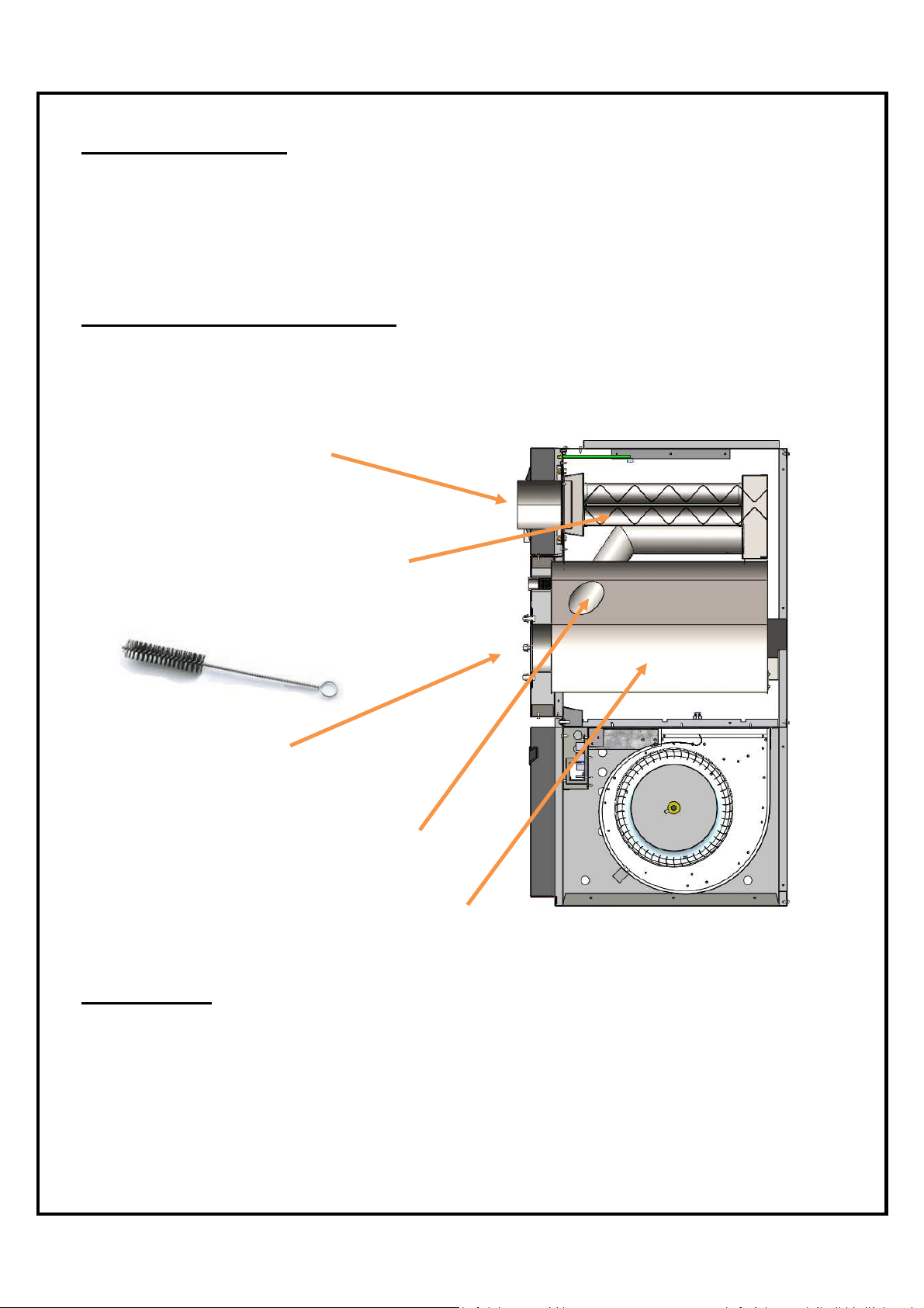
Step 3:
Remove the burner
Step
2
:
Step
5
:
Step
4
:
Step
1
:
CHANGING NOZZLE
It is recommended that the nozzle be replaced once a year. If a new nozzle of a different size
is installed, change the blower speed according to section BURNER INSTALLATION AND
SPECIFICATIONS (see table at page 14) or operating decal as required
CLEANING HEAT EXCHANGER
Heat exchanger must be inspected every heating season. Refer to instructions and pictures
below.
Remove the breech plate
Remove the baffles and clean
the round tubes if needed (use a
2’’ diameter brush)
Clean the transitions tubes if needed
Clean the combustion chamber if needed
AIR FILTERS
To maintain furnace performance and safety, replace dirty filters as required or at least once
every heating season or as required. Use new approved disposable filters of the same size
and type. Dirty, clogged or wrong sized filters will impair the furnace performance and may
cause the furnace to shut down or overheat
23
Page 25
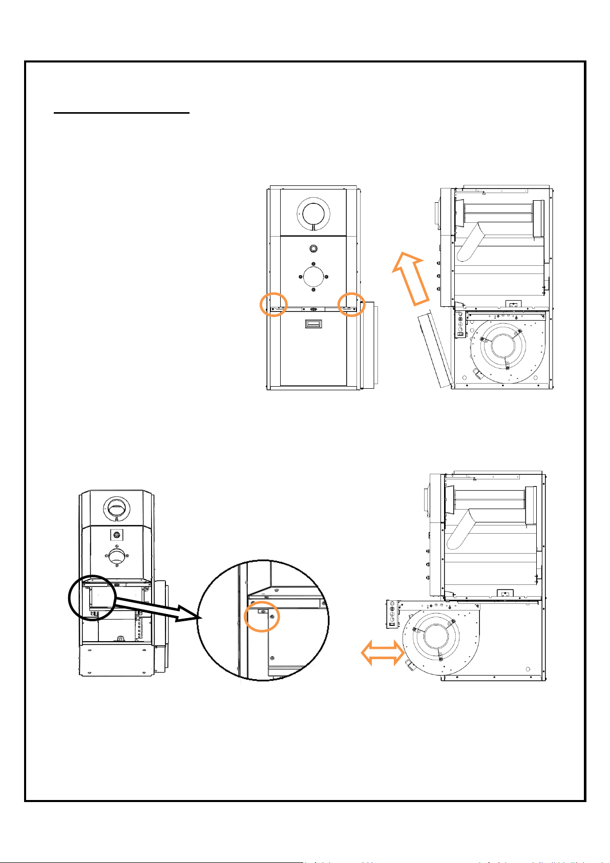
BLOWER REMOVAL
This furnace has a blower sealing system, which is designed to be tight and rattle free. Refer
to the instructions and pictures below.
1) Shut off oil and power to furnace.
2) Remove the two (2) screws
securing the blower door (Figure
1).
3) Open blower compartment
(Figure 2).
4) Disconnect the wiring to the
blower motor.
5) Remove the screw securing the
blower side to the separating
panel (Figure 3).
6) Slide the blower toward you and
get the blower out of the furnace
(Figure 4).
Figure 1 Figure 2
Figure 3 Figure 4
24
Page 26
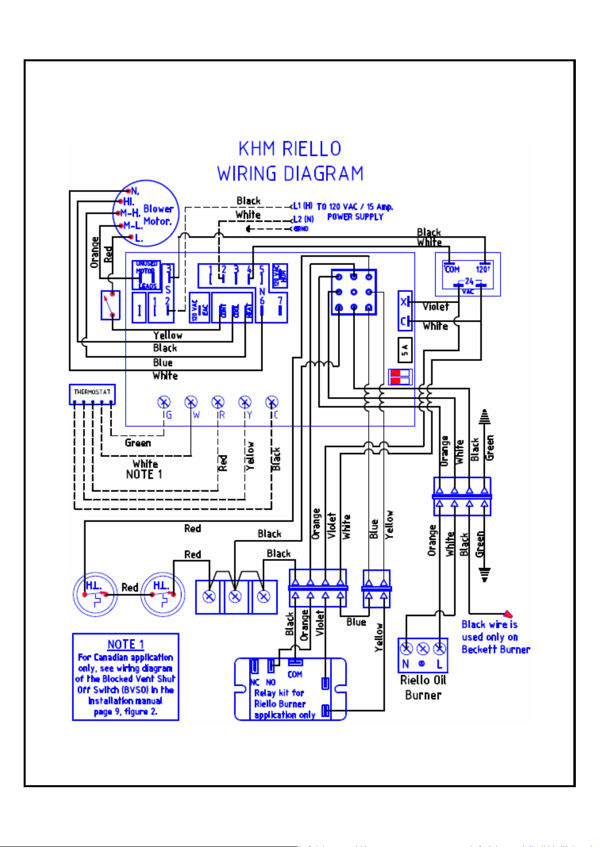
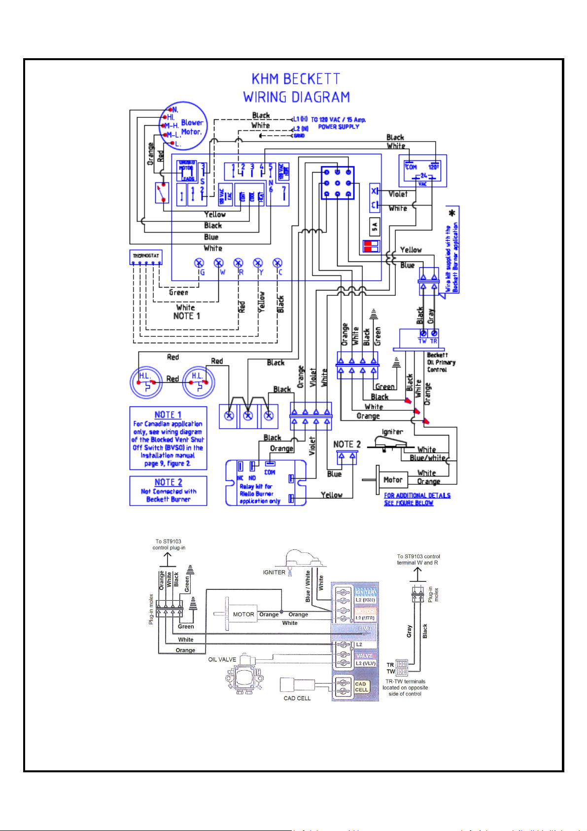
8.0 ELECTRICAL / WIRING DIAGRAMS
25
Page 27
*
Transforming the electric box for a Beckett burner application, see page 27
GeniSys control schematic with the ST9103 Board
26
Page 28
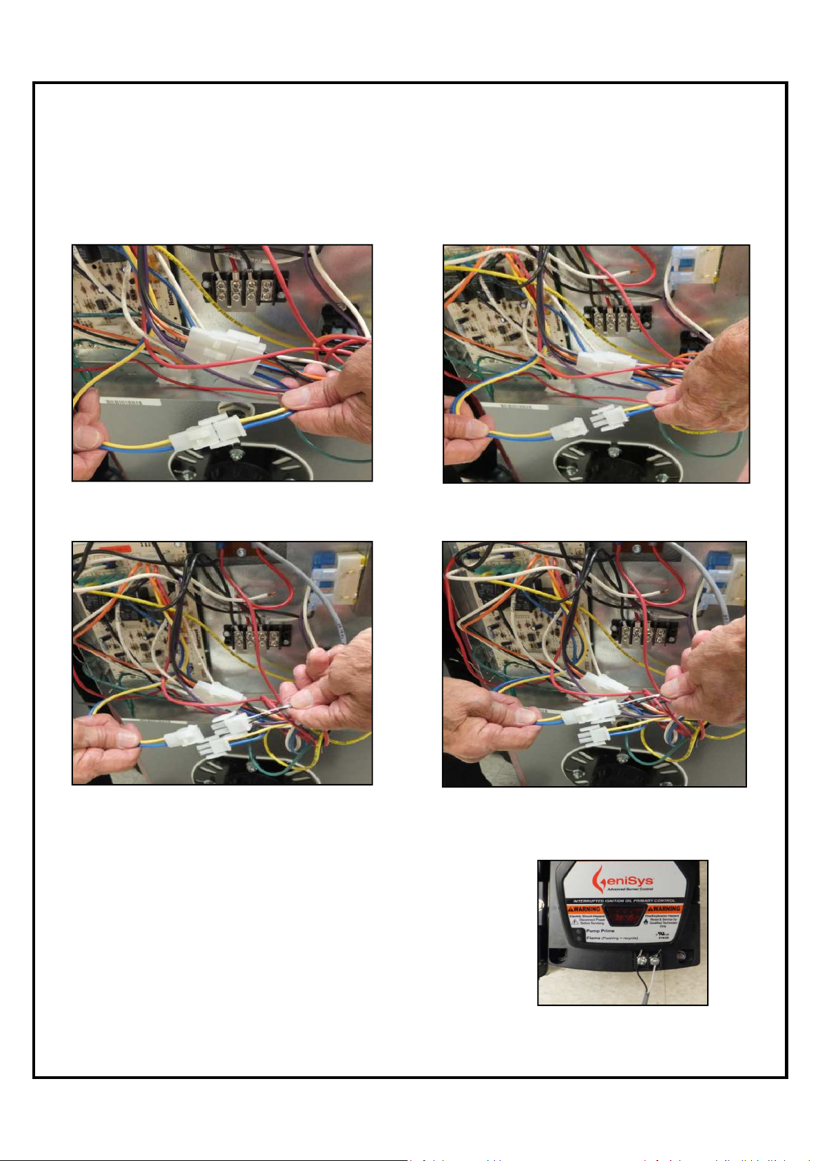
Electric box with a Beckett burner application
Transforming the factory assembly Riello electric box
STEP 1 : Locate and disconnect the 2-pin Molex connector.
STEP 2 : Connect the 2-pin connector to the 2-pin harness
provided in the Beckett burner box.
STEP 3 : Connect the 2 wires (black and
grey) of the 2-pin harness to the TW and
TR connection on the GeniSys primary
control
to a Beckett electric box
27
Page 29
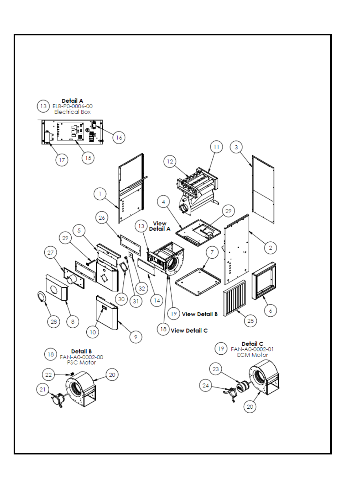
9.0 EXPLODED PARTS VIEW
KHM-1 / 090 – Exploded Parts View
28
Page 30
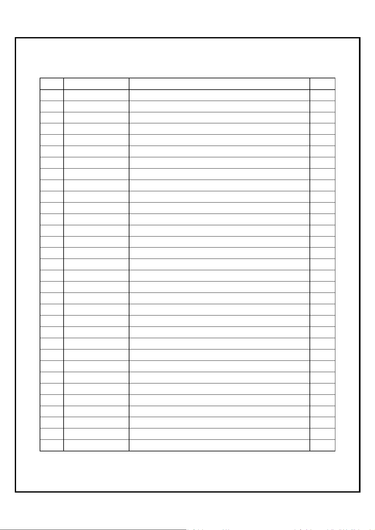
KHM-1 / 090 – Part List
ITEM PART NUMBER
1 CAB-A0-0019-00 Left Panel Assembly 1
2 CAB-A0-0020-00 Right Panel Assembly 1
3 CAB-A0-0018-00 Rear Panel Assembly 1
4 CAB-A0-0016-00 Blower Panel Assembly 1
5 CAB-A0-0021-00 Front Panel Assembly 1
6 CAB-A0-0022-00 20’’ x 20’’ Filter Holder Assembly 1
7 CAB-P0-0045-00 Base Panel 1
8 CAB-P0-0052-00 Front Door Panel 1
9 CAB-P0-0051-00 Blower Door Panel 1
10 3HN-00-PULL-00 Handle Flush Pocket Pull 1
11 HEX-A0-0009-00 Heat Exchanger Assembly 1
12 HEX-P0-0064-00 Pipe Baffle Hi-Boy 7
13 ELB-A0-0006-00 Electrical Box Assembly - Hi-Boy Model 1
DESCRIPTION QTY
14 ELB-P0-0014-00 Cover Electric Box - Hi-Boy Model 1
15 4CB-00-FAN0-00 ST9103A1028 Electronic Board 1
16 4RY-00-24V0-00 Relay AE04001 24VAC Form C SPDT 24V 1
17 4TF-00-40VA-00 Transformer HTC-01A0BB01 40 VA 1
18 FAN-A0-0002-00 Fan Motor Assembly KLR-090 PSC Motor 1
19 FAN-A0-0002-01 Fan Motor Assembly KLR-090 ECM Motor 1
20 3BU-10-08DD-00 Blower 10'' x 8'' Direct Drive (G10-8DD) 1
21 3BM-50-4SDD-01 Motor Blower 1/2 HP Direct Drive 4SP EMERSON 1
22 4CA-00-705M-00 Capacitor 7.5 µF 370VAC 70C 60 Hz 1
23 3BM-50-ECM0-02 Motor Blower 1/2 HP ECM Ecotech EMERSON 1
24 1SB-00-BUMR-00 Bracket Motor Mounting Direct Drive Blower 1
25 3AF-02-2020-01 Filter Air 20" x 20" x 2" Non-Pleated (Strata Type) 1
26 INS-P0-0015-00 Low-Boy Rear Insulation 2
27 HEX-A0-0013-00 Front Collector Assembly 1
28 CAB-P0-0121-00 Front Flue Collar 1
29 4SD-00-0185-00 Control Limit Snap Disc (185°) Au to Reset (L185-40F)
2
30 INS-P0-0017-00 Burner's Flange Insulation 1
31 3SG-0P-1030-5A Glass Sight Clear 1" NPT Hex With THD Seal 1
32 INS-P0-0018-00 Sight Glass Insulation 1
29
Page 31
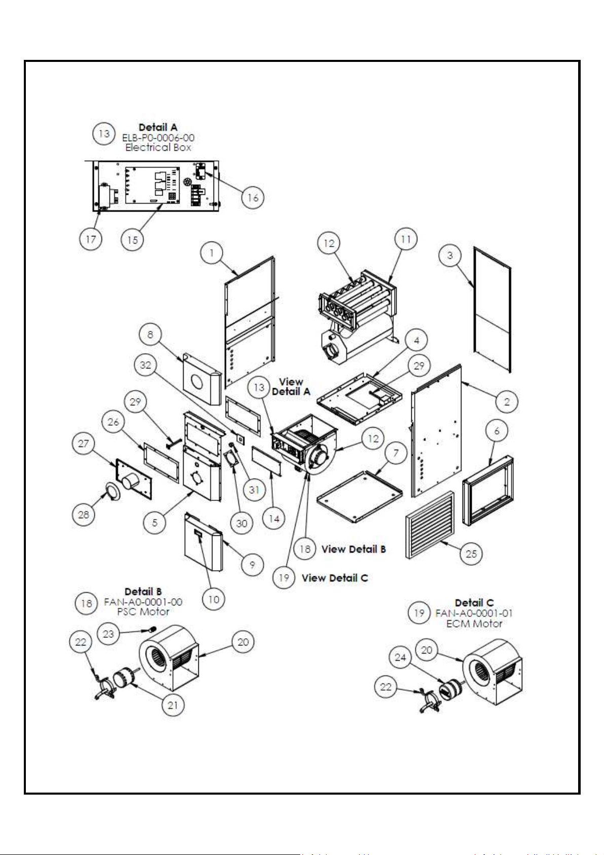
KHM-2 / 140 – Exploded Parts View
30
Page 32
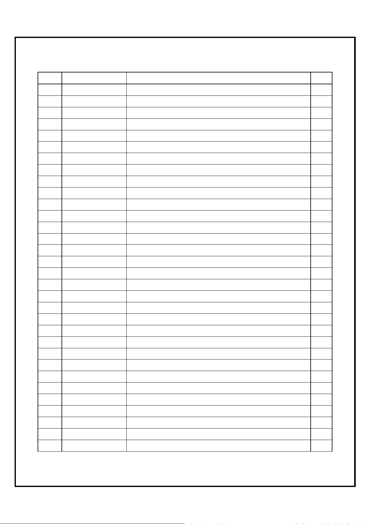
KHM-2 / 140 – Part List
ITEM PART NUMBER
1 CAB-A0-0027-00 Left Panel Assembly 1
2 CAB-A0-0028-00 Right Panel Assembly 1
3 CAB-A0-0026-00 Rear Panel Assembly 1
4 CAB-A0-0024-00 Blower Panel Assembly 1
5 CAB-A0-0029-00 Front Panel Assembly 1
6 CAB-A0-0030-00 20’’ x 25’’ Filter Holder Assembly 1
7 CAB-P0-0061-00 Base Panel 1
8 CAB-P0-0065-00 Front Door Panel 1
9 CAB-P0-0051-00 Blower Door Panel 1
10 3HN-00-PULL-00 Handle Flush Pocket Pull 1
11 HEX-A0-0011-00 Heat Exchanger Assembly 1
12 HEX-P0-0064-00 Pipe Baffle Hi-Boy 11
13 ELB-A0-0006-00 Electrical Box Assembly - Hi-Boy Model 1
14 ELB-P0-0014-00 Cover Electric Box - Hi-Boy Model 1
15 4CB-00-FAN0-00 ST9103A1028 Electronic Board 1
DESCRIPTION QTY
16 4RY-00-24V0-00 Relay AE04001 24VAC Form C SPDT 24V 1
17 4TF-00-40VA-00 Transformer HTC-01A0BB01 40 VA 1
18 FAN-A0-0001-00 Fan Motor Assembly KHM-140 PSC Motor 1
19 FAN-A0-0001-01 Fan Motor Assembly KHM-140 ECM Motor 1
20 3BU-12-00DD-00 Blower 12'' Direct Drive (GT12-10DD) 1
21 3BM-75-4SDD-01 Motor Blower 3/4 HP Direct Drive 4SP EMERSON 1
22 1SB-00-BUMR-00 Bracket Motor Mounting Direct Drive Blower 1
23 4CA-00-156M-2B Capacitor 15 µF 370VAC 70C 60 Hz 1
24 3BM-75-4SDD-02 Motor Blower 3/4 HP ECM Ecotech EMERSON 1
25 3AF-02-2025-01 Filter Air 20" x 25" x 2" Non-Pleated (Strata Type) 1
26 INS-P0-0020-00 Hi-Boy Front Insulation 2
27 HEX-A0-0010-00 Front Collector Assembly 1
28 CAB-P0-0121-00 Front Flue Collar 1
29 4SD-00-0185-00 Control Limit Snap Disc (185°) Au to Reset (L185-40F) 2
30 INS-P0-0017-00 Burner's Flange Insulation 1
31 3SG-0P-1030-5A Glass Sight Clear 1" NPT Hex With THD Seal 1
32 INS-P0-0018-00 Sight Glass Insulation 1
31
Page 33
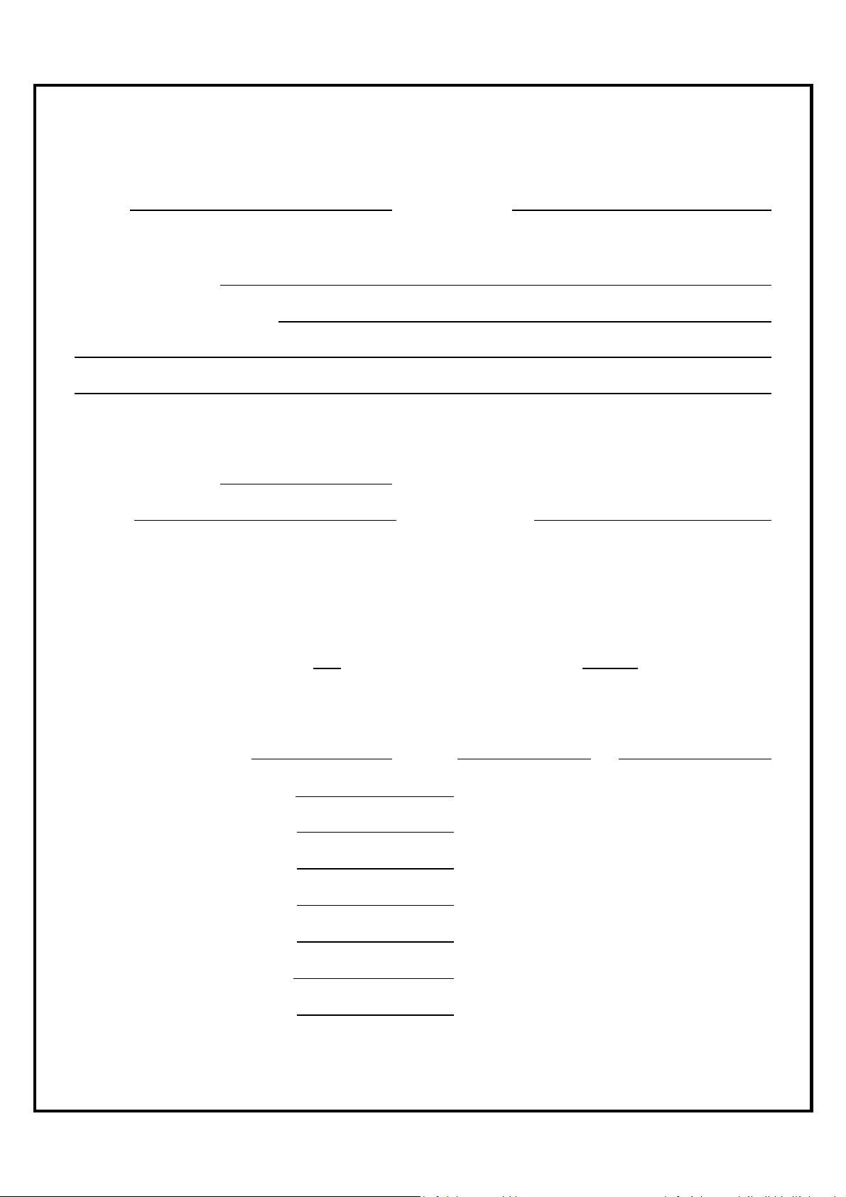
10. START-UP TEST RESULTS
Model: Serial Number:
Unit configuration: Upflow____ Downflow_____ Horizontal left_____ Horizontal right_____
Date of installation:
Installer (name & address):
START-UP TEST RESULTS
Size of unit (Btu/h):
Nozzle: Oil Pressure (psi):
Chimney____________ Direct vent system (DVS) ____________
Burner adjustments:
RIELLO F3___ RIELLO F5___ BECKETT AFG L2___ BECKETT AFG F3____
Turbulator: ______ Air band: ______
Air Gate: ________ Air shutter______
Smoke result: #0 TRACE #1
Combustion Results:
CO2 %
Chimney draft: “ W.C.
Ambient temperature: °F
Gross flue temperature: °F
Temperature rise: °F (see page 33)
External total static pressure: “ W.C. (see page 33)
A/C Coil total resistance: “ W.C. (see page 33)
32
Page 34
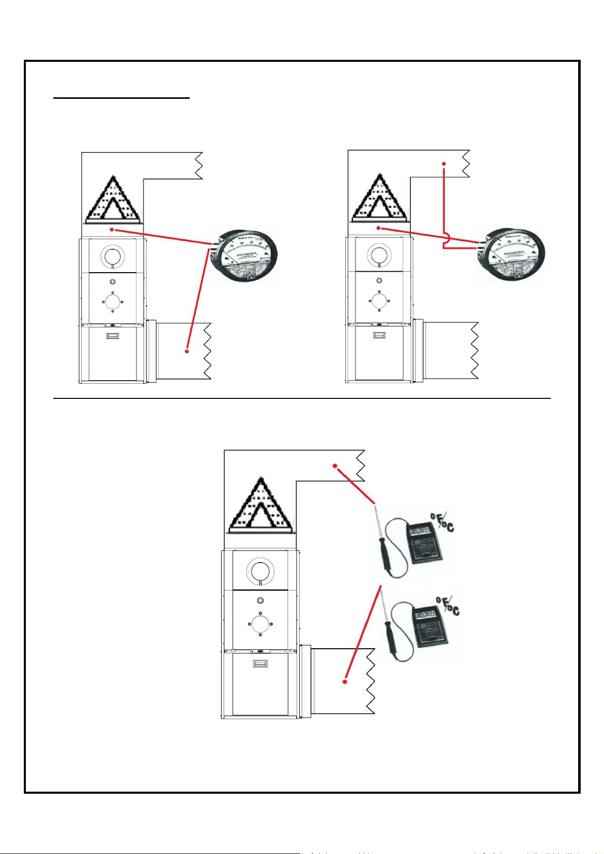
Ps
Pc
Ps
TEST PROCEDURES
External Total Static Pressure Reading A/C Coil Total Resistance Reading
Supply Pressure (Ps) + Return Pressure (Pr)
Coil Pressure (Pc) - Supply Pressure (Ps)
Pr
Temperature Rise Reading ***
Supply Temp. (Ts) - Return Temp. (Tr)
*** Probe must not be in direct sight of heat exchanger.
Ts
Tr
33
Page 35
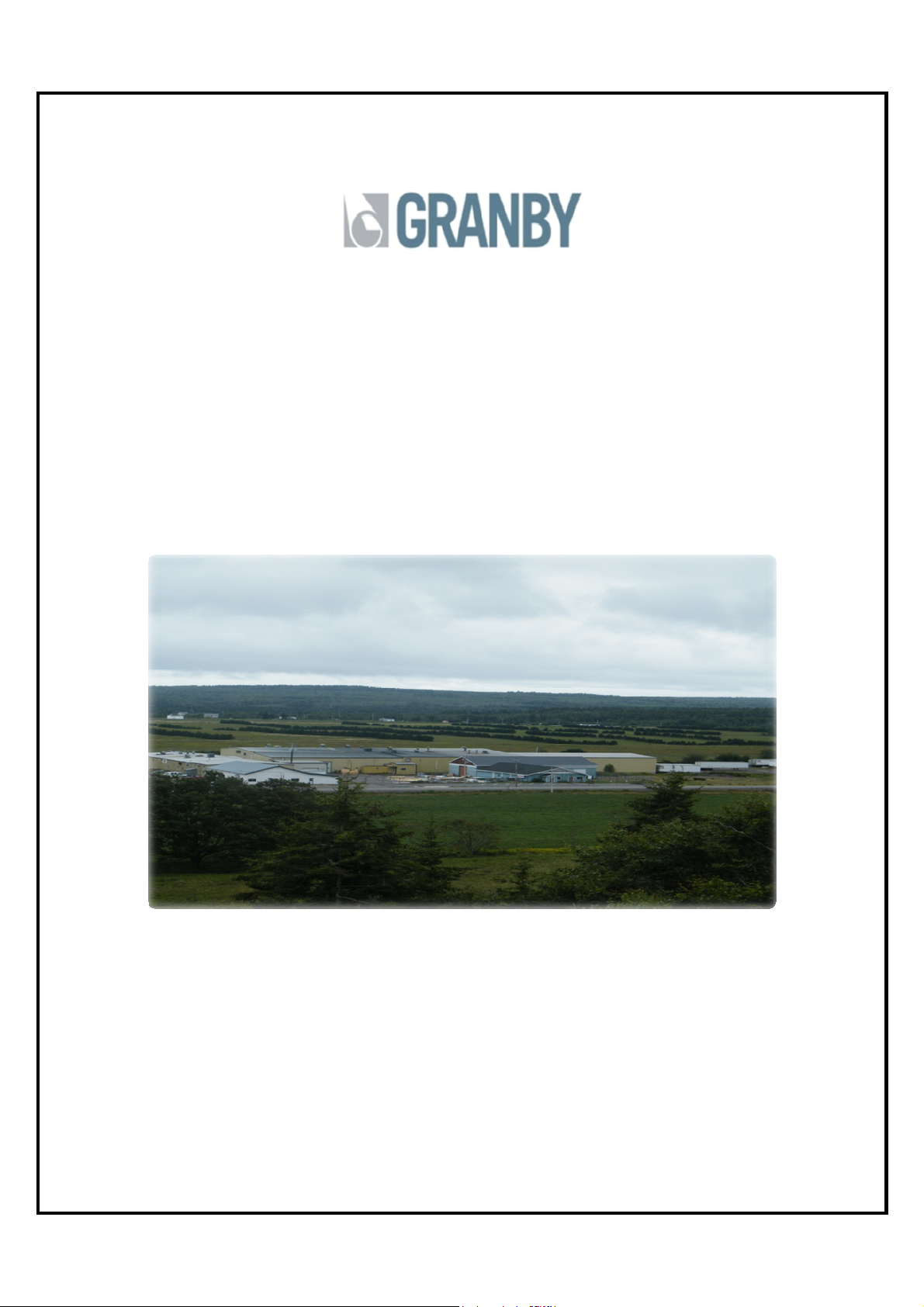
Granby Furnaces Inc. manufactures a full line of oil-fired furnaces
in its 70,000 square feet facility. Granby products are sold across
Canada and the United States through a distribution network.
Our team of engineers, designers and technicians continually
research and develop products to go beyond the demanding
specifications of today’s certifications.
Thank you
Thank you for choosing Granby
Thank you Thank you
for choosing Granby....
for choosing Granbyfor choosing Granby
34
 Loading...