

Granby KHM-100 GAS, KHM SERIES, KHM-200 GAS Installation, Operation And Service Manual
Installation, Operation and
Service Manual
KHM SERIES
80% + EFFICIENCY
GAS FIRED CATEGORY I HI-BOY FURNACE
KHM-100 GAS
KHM-200 GAS
KHM-100 Illustration
INSTALLATIONS MUST MEET ALL LOCAL AND FEDERAL
CODES THAT MAY DIFFER FROM THIS MANUAL
Please read the manual in its entirety before beginning installation.
This manual must be kept with the furnace for future reference.
GRANBY FURNACES INC.
PO Box 637
12118 Hwy 209
Parrsboro Nova Scotia Canada
B0M 1S0
902-254-2543
www.granbyindustries.com
04-07-2015 G2014-E2G-Rev.B

1
TABLE OF CONTENTS
KHM
Gas
1.0 IMPORTANT SAFETY ADVICE 3
2.0 PRODUCT INFORMATION 5
3.0
FURNACE INSTALLATION 8
4.0 ACCESSORY INSTALLATION 15
5.0 BURNER INSTALLATION AND SPECIFICATIONS 19
5.1 ASSEMBLY & INSTALLATION OF BURNER 19
5.2 GAS-FIRED FURNACE LIGHTING INSTRUCTIONS 20
5.2 TECHNICAL INFORMATION 21
6.0 FURNACE OPERATION AND SETTINGS 22
6.1 BLOWER SETTING 22
6.2 FAN TIMER CONTROL BOARD (ST9103 A 1028) 23
6.3 ST9103 A 1028 CONTROL BOARD SEQUENCE 24
6.4 SERVICING – FAN TIMER (ST9103 A 1028) 25
7.0
SERVICE 27
7.1 BURNER CLEANING NOTES 30
8.0 ELECTRICAL / WIRING DIAGRAMS 31
9.0 EXPLODED PARTS VIEW 32
KHM-100 32
KHM-200 34
10. START-UP TEST RESULTS 36
2
NOTE: THE BURNER INSTRUCTION MANUAL AND THE
B
URNER USER’S INFORMATION MANUAL ARE
CONSIDERED PART OF THIS MANUAL AND THEIR
INSTRUCTIONS MUST BE FOLLOWED EXCEPT WHEN
SPECIFICALLY MENTIONNED IN THIS MANUAL.
WARNING: If the information in this
manual is not followed exactly, a fire or
explosion may result, causing property
damage, personal injury or death.
- D
o not store or use gasoline or other
flammable vapors or liquid in the vicinity of
this or any other appliance.
- WHAT TO DO IF YOU SMELL GAS
o Do not try to light the appliance,
o Do not touch any electrical switch; do not
use any phone in your building,
o Immediately call your gas supplier from an
outside phone. Follow the gas supplier’s
instructions,
o If you cannot reach your gas supplier, call
the fire department.
- I
nstallation and service must be performed
by a qualified installer, service agency or
the gas supplier.
3
1.0 IMPORTANT SAFETY ADVICE
Please read and understand this manual before installing, operating or servicing the
furnace. To ensure you have a clear understanding of the operating procedures of the
appliance please take the time to read the IMPORTANT SAFETY ADVICE section of this
manual.
• Use only with Natural gas or Propane gas. Refer to the furnace rating plate.
• Install this furnace only in a location and position as specified in Section 3 of
these instructions.
• Provide adequate combustion and ventilation air to the furnace space as
specified in Section 3 of these instructions.
WARNING
FIRE OR EXPLOSION HAZARD
Never test for gas leaks with an open flame. Use a commercially available soap
solution made specifically for the detection of leaks to check all connections, as
specified in Section 5 of these instructions.
• Always install furnace to operate within the furnace’s intended temperature-rise
range with a duct system that has an external static pressure within the allowable
range, as specified in Section 5 of these instructions. See furnace rating plate.
• When a furnace is installed so that supply ducts carry air circulated by the
furnace to areas outside the space containing the furnace, the return air shall also
be handled by duct(s) sealed to the furnace casing and terminating outside the
space containing the furnace.
• This gas-fired furnace is not intended for installation in a residential garage.
• This furnace is not factory approved for installation at altitude higher than 2000
feet.
• Excessive exposure to contaminated combustion air will result in safety and
performance related problems.
o Sample List of Contaminants to be Avoided
The recommended source of combustion air is to use the outdoor air
supply. However, the use of indoor air in most applications is
acceptable except as follows:
• 1. If the furnace is installed in a confined space it is
recommended that the necessary combustion air come from
the outdoors by way of attic, crawl space, air duct, or direct
opening.
• 2. If outdoor combustion air is used, there must be no
exposure to the installations or substances listed in “3” below.
4
• 3. The following types of installation may require
OUTDOOR AIR for combustion, due to chemical
exposures:
o - Commercial buildings
o - Buildings with indoor pools
o - Furnaces installed in laundry rooms
o - Furnaces installed in hobby or craft rooms
o - Furnaces installed near chemical storage areas
o Exposure to the following substances in the
combustion air supply may also require OUTDOOR
AIR for combustion:
- Permanent wave solutions
- Chlorinated waxes and cleaners
- Chlorine based swimming pool chemicals
- Water softening chemicals
- De-icing salts or chemicals
- Carbon tetrachloride
- Halogen type refrigerants
- Cleaning solvents (such as
perchloroethylene)
- Printing inks, paint removers, varnishes, etc.
- Hydrochloric acid
- Cements and glues
- Antistatic fabric softeners for clothes dryers
- Masonry acid washing materials
WARNINGS
NEVER b
urn garbage or paper in the unit.
NEVER store combustible material around it.
CAUTION
DO NOT START THE BURNER UNTIL ALL FITTINGS, COVERS AND DOORS ARE IN
PLACE. DO NOT TAMPER WITH THE FURNACE OR CONTROLS, CALL A QUALIFIED
BURNER TECHNICIAN. DO NOT STORE OR USE GASOLINE OR OTHER FLAMMABLE
VAPOURS AND LIQUIDS IN THE VICINITY OF THIS UNIT OR ANY OTHER APPLIANCE.
DANGER
Do not use this furnace as a construction heater. Use of this furnace as a construction
heater exposes it to abnormal conditions, contaminated combustion air and lack of air
filtering. Failure to follow this warning can lead to premature furnace failure which
could result in a fire hazard and/or bodily harm and/or materials damages.
5
IMPORTANT
This manual contains instructional and operational information
for the KHM GAS FIRED FURNACE. Read the instructions
thoroughly before installing furnace or starting the burner.
Consult local authorities about your local FIRE SAFETY
REGULATIONS. All installations must be in accordance with
local state or provincial codes. Improper installation will result
in voiding of warranty.
THE INSTALLATION OF YOUR GAS-FIRED FURNACE MUST CONFORM TO
T
HE REQUIREMENT OF THE AUTHORITY HAVING JURISDICTION OR IN
THE ABSENCE OF SUCH REQUIREMENTS, TO THE NATIONAL FUEL GAS
CODE ANDSI Z223.1/NFPA 54 AND/OR NATIONAL GAS AND PROPANE
INSTALLATION CODE CAN/CSA B149.1.
2.0 PRODUCT INFORMATION
CLEARANCE (minimum) TO COMBUSTIBLES (Operation and Service Clearances)
Top & Sides of Supply Plenum 1” (25 mm)
Front (Maintenance) 24” (610 mm)
Rear 0” (0 mm)
First Side 0” (0 mm)
Other Side 0” (0 mm)
Flue Pipe 9” (229 mm)
Floor Combustible
Furnaces for indoor installation on combustible flooring shall not be installed directly
on carpeting, tile or other combustible material other than wood flooring.
DRAFT PRESSURE
B
reech draft pressure -0.01” wc minimum
AIR/BLOWER DATA
Maximum External static – Non A/C 0.5” wc
Maximum External static – A/C 0.5” wc
Maximum cooling 3.0 tons… KHM-100
5.0 tons… KHM-200
Maximum air temperature rise 75 Degrees F
High Limit, max design outlet temp 185°F
Thermostat anticipator 0.2 amps
6
MOTOR/BLOWER
KHM-100: 1/2 hp 4 Speed / G10-8 DD or 1/2 hp ECM / G10-8
KHM-200: 3/4 hp 4 Speed / GT12-10DD or 3/4 hp ECM / GT12-10
FAN/HIGH LIMIT CONTROL
Honeywell ST9103 Fan Center & Thermo-Disk (7” stem)
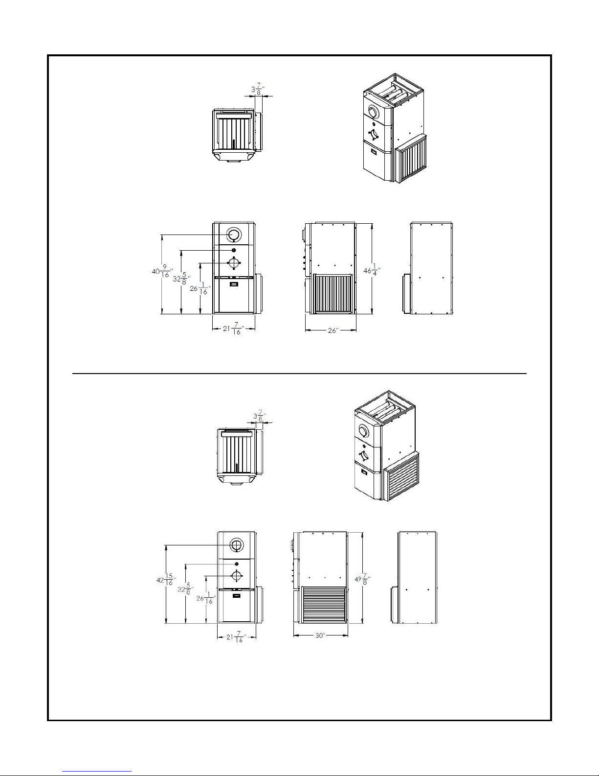
DIMENSIONS (KHM-100)
Depth 26” (660 mm)
Height 46 1/4” (1175 mm)
Width 21 7/16” (545 mm)
DIMENSIONS (KHM-200)
D
epth 30” (762 mm)
Height 49 7/8” (1267 mm)
Width 21 7/16” (545 mm)
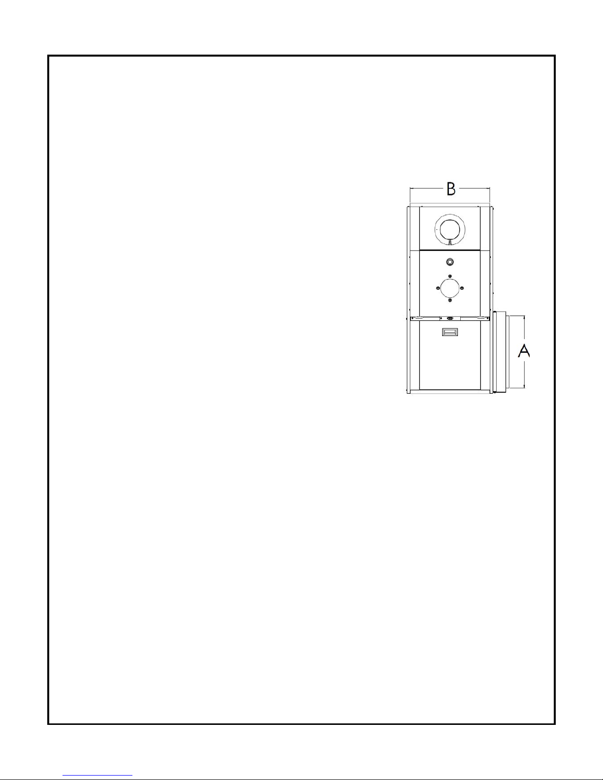
PLENUM DIMENSIONS (KHM-100)
Cold air return (A) 18” x 18” (457 x 457 mm)
Hot air supply (B) 20” x 20” (508 x 508 mm)
PLENUM DIMENSIONS (KHM-200)
Cold air return (A) 23” x 18” (584 x 457 mm)
Hot air supply (B) 24” x 20” (610 x 508 mm)
AIR FILTERS
KHM-100 20” x 20” x 2” Pleated UL approved
KHM-2 00 25” x 20” x 2” Pleated UL approved
A/C COIL LOCATION
Mi
nimum height above the heat exchanger 4” (152 mm)
See A/C Coil Manufactures Requirements
SMOKE-PIPE CONNECTION
5” Chimney
CLEANOUTS
Front Cover & Burner Opening
THERMOSTAT
Any thermostat
FUEL
Natural Gas or Propane Gas
ELECTRICAL – CANADA:120 Volts, 60 Hz. Less than 12 amps, circuit protection 15 amps.
USA: 13.3 amps, circuit protection 20 amps.
7
KHM-100 - DIMENSIONS
Dimensions are in inches
KHM-200 - DIMENSIONS
Dimensions are in inches

8
3.0 FURNACE INSTALLATION
GAS PIPING
Gas piping must conform to local requirements.
Install according to the applicable code such as NATIONAL FUEL GAS CODE ANDSI
Z223.1/NFPA 54 AND/OR NATIONAL GAS AND PROPANE INSTALLATION CODE
CAN/CSA B149.1.
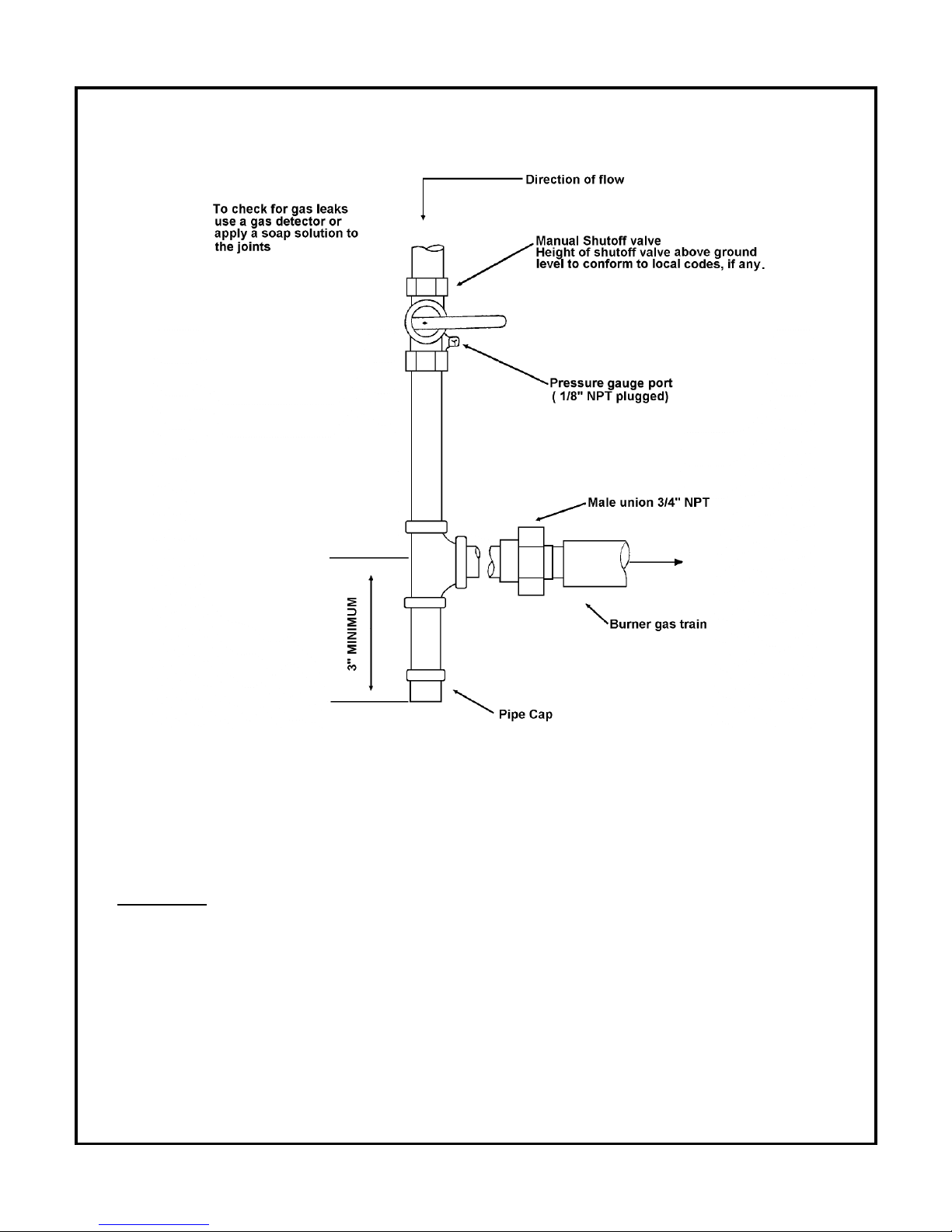
The gas piping must be installed between the gas meter and the combination gas valve
(located upstream of the Riello gas burner on the furnace. The gas valve has a knob acting as
a shut-off valve to stop gas flow. It is recommended to install a manual shut-off valve upstream
of the gas valve to facilitate service of the gas valve. The gas valve also has pressure tapping
for inlet pressure as well as outlet pressure. The outlet pressure of the gas valve is also
referred as manifold pressure in this manual.
If local codes allow the use of a flexible gas appliance connector, always use a new
listed connector. Do not use a connector which has previously serviced another gas
appliance
WARNING:
• Connect from the gas supply to the burner combination gas valve inlet using new, clean
black iron pipe and malleable iron fittings only. Do not use copper, brass, cast iron or
galvanized pipe or fittings.
• Provide support for gas piping. Do not rest weight of piping on burner gas valve.
• Apply pipe dope sparingly at all joints. Use only pipe dope listed for use with propane
gas. Do not use pipe sealing tape. In doubt consult CSA B149.1 or NFPA 54 or the
authorities having jurisdiction.
• Do not hold gas valve with a pipe wrench. Use crescent wrench or other smooth jawed
device. Do not over-tighten.
• Failure to comply with above could result in severe personal injury, death or
substantial property damage.
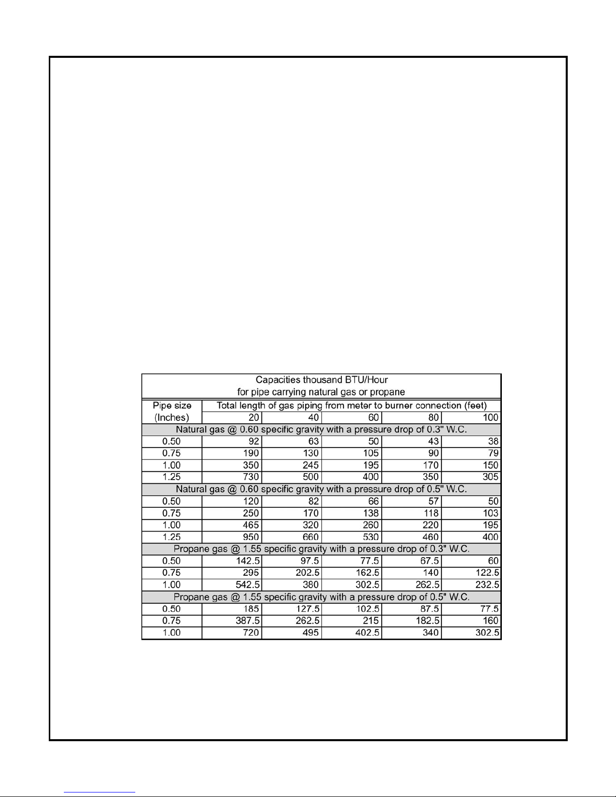
1. If possible, install a new gas line directly from the gas meter. If you are using an existing
gas line, verify it is clean and in good condition and verify it is large enough to handle the
load of all connected appliances. See the table below for guidance on pipe sizes.
2. When branching from a common gas line, do not tap from the bottom or horizontal sections,
only from the side or top.
3. Install a main manual shutoff valve, sediment trap and ground joint union near the burner
combination gas valve connection as shown below.
9
GAS SUPPLY PRESSURE
•
Maximum supply pressure: 13 inches W.C.
• Minimum supply pressure: 7” inches W.C.
WARNING:
• Do not expose the combination gas valve to gas pressures in excess of 14” W.C. The
valve has a safety mechanism that interrupt the flow of gas over 14” W.C. In any event
higher pressure could damage the valve seat, resulting in potentially hazardous
conditions. When pressure testing at higher pressures, disconnect burner from gas line
before testing.
10
• If the gas supply pressure can exceed 14 inches of water column at any time, you must
i
nstall a lockup type gas pressure regulator in the gas supply piping, ahead of the main
manual gas valve on the burner.
• The furnace and its gas connections must be leak tested before placing the boiler in
operation.
• Enough combustion air should be provided to the gas-fired furnace in accordance with
the section “Air for combustion and ventilation” of the National Fuel Gas Code ANSI
Z223.1/NFPA 54 or clause 8,2, 8,3 or 8.4 of Natural gas and Propane installation code
CAN/CSA B149.1, or applicable provisions of the local building codes.
TEST AND PURGE GAS LINE
1. Read warning above.
2. Pressure test and purge the line. Pressure testing should be done by the gas supplier or
utility, following all applicable codes.
11
PLACEMENT & VENTING
THE INSTALLATION OF YOUR GAS-FIRED FURNACE MUST CONFORM TO
THE REQUIREMENT OF THE AUTHORITY HAVING JURISDICTION OR IN
THE ABSENCE OF SUCH REQUIREMENTS, TO THE NATIONAL FUEL GAS
CODE ANDSI Z223.1/NFPA 54 AND/OR NATIONAL GAS AND PROPANE
INSTALLATION CODE CAN/CSA B149.1.
FLOOR SUPPORT COMBUSTIBLE – If required, support furnace on five (5) concrete
blocks. Make sure the center of the furnace base is supported.
Approved for installation on combustible floors. Make sure that all
clearances are respected.
CHIMNEY/VENT
Breech is certified for 5” vent pipe. Keep vent/flue pipe as short as
possible with a minimum upward slope of ¼’’ per foot. Vent/flue pipes
MUST NOT pass through a ceiling. Maximum flue gas temperature is
480°F.
ADDITIONAL CHIMNEY INFORMATIONS
WARNING
CARBON MONOXIDE POISONING HAZARD
Failure to follow the steps outlined below for each appliance connected to the venting
system being placed into operation could result in carbon monoxide poisoning or
death.
When an existing furnace is removed from a common venting system, the common venting
system is likely to be too large for proper venting of the appliances connected to it. At the time
of removal of the existing furnace, the following steps shall be followed with EACH appliance
remaining connected to the common venting system, while the other appliances remaining
connected to the common venting system are not in operation:
1. Seal any unused openings in the venting system.
2. Visually inspect the venting system for proper size and horizontal pitch and determine
there is no blockage or restriction, leakage, corrosion and other deficiencies which could
cause an unsafe operation.
3. Insofar as is practical, close all building doors and windows and all doors between the
space in which the appliances remaining connected to the common venting system are
located and other spaces of the building. Turn on clothes dryer and any appliance not
connected to the common venting system. Turn on any exhaust fans, such as range
hoods and bathroom exhausts, so they will operate at maximum speed. Do not operate
a summer exhaust fan. Close fireplace dampers.
 Loading...