

Granby KHE-00-G023-03, KHE-00-G015-03, KHE-00-G018-03, KHE-00-G020-03, KHE-00-G027-05 Installation, Operation And Service Manual
...
Installation, Operation and Service
Manual
Conforto
Electric
Furnace
HE 10 TO 27kW
K
INSTALLATIONS MUST MEET ALL LOCAL AND FEDERAL CODES THAT MAY
DIFFER FROM THIS MANUAL
Please read the complete manual before beginning installation. This
manual must be kept with the furnace for future reference. For
maintenance or question, please refer to your installer – contractor directly.
02-13-2018 G2018-A1 Rev. A

TABLE OF CONTENTS
1.0 IMPORTANT SAFETY ADVICE 3
2.0 PRODUCT INFORMATION 3
3.0 INSTALLATION 4
4.0 HIGH VOLTAGE CONNECTIONS 6
5.0 PANEL DISPLAY, SWITCHES AND CUICUIT BREAKER 7
6.0 TECHNICAL INFORMATION 10
7.0 HEATING OUTPUT RATES BY STAGES 11
8.0 COMMISIONING CHECKLIST 11
9.0 KHE SERIES ELECTRICAL FURNACE 12
10. WIRING DIAGRAM – PSC & ECOTECH RESCUE MOTORS 13
11 EXPLODED VIEW KHE 14
2
1.0 IMPORTANT SAFETY ADVICE
Please read and understand this manual before installing, operating or servicing the
furnace. To ensure you have a clear understanding of the operation of the unit please take the
time to read the IMPORTANT SAFETY ADVICE section of this manual.
WARNING – BASIC SAFETY WARNINGS
KNOW the location of the emergency disconnect switch for the unit.
EXAMINE the package before installation to ensure it did not get damaged during shipping.
ENSURE that the unit is connected to a properly sized duct system before controller is powered.
Failure to do so will result in damage to the heating elements, voiding the warranty.
WARNING – BEST PRACTICES FOR OPTIMAL OPERATION
DO NOT ATEMPT DO INSTALL YOURSELF OR MAKE ANY REPAIRS IF YOU ARE NOT A
QUALIFIED TECHNICIAN, CALL A QUALIFIED HEATING TECHNICIAN.
DANGER
Do not use this furnace as a construction heater. Use
heater exposes it to abnormal conditions, contaminated circulating air and air filtering.
Failure to follow this warning can lead to premature furnace failure which could result in
a fire hazard and/or bodily harm and/or material damage and will void its manufacturer’s
warranty.
of this furnace as a construction
IMPORTANT
This manual is intended to inform the installer of installation, operation and maintenance
procedures for trouble free operation of the Conforto KHE electric furnace. It is essential that
the service technician carefully reads this manual to fully understand the furnace and its
installation, operation and maintenance procedures before servicing the furnace or the heating
system as operating procedures may vary depending on furnaces manufacturers. The Conforto
KHE electric furnace is designed and manufactured with quality components for maximum life
expectancy, durability and requires minimum maintenance and service. To insure a satisfactory
installation, it is imperative that the instructions in this manual be followed carefully before
operating the heating system. Failure to do so may result in breach of warranty.
2.0 PRODUCT INFORMATION
The Conforto KHE warm air electric furnace is a multi-po
installation in the up flow, down flow or horizontal
with a central heat-pump or central cooling system.
sitional design allowing for an
fl
ow positions. This appliance may be used
3

INSTALLATION OVERVIEW
Install this appliance in accordance with these instructions and all national and local
building/safety codes and requirements.
Only connect this furnace to a duct system with a maximum
pressures in excess will result in reduced air flow and potential elevated discharge air
temperatures during heating cycles and reduced discharge air temperatures during cooling
cycles.
Do not operate this furnace without both supply and retu
place or with less than 0.20” W.C, external static pressure.
INSPECTION
As soon as you receive this unit un package and inspe
damage has resulted during the shipping process.
static pressure of 0.60” W.C. Static
rn air ducts installed with air filters in
ct it thoroughly to ensure that no
3.0 INSTALLATION
General
These furnaces must be properly installed in compliance
standard codes. This appliance requires 240Vac single phase, 60Hz voltage.
The supply power lead shall enter the control enclosure of the furnace through the knockout
provided on the right-hand side of the furnace. This will ensure the required separation between
the low voltage and high voltage leads.
Knockouts are provided for 115Vac and 24Vac connectio
cleaners on both sides of the furnace.
Always ensure that the installation protects all electric
Attention must be given to the placement of A/C coils and drains.
fl
A non-combustible base is needed for counter
Adequate access must be provided at the front of this furnace for service.
ow installations on combustibles floors.
with all national and local safety
ns for humidifiers and electronic air
al components from exposure to water.
ATTENTION: the front of the appliance must always remain accessible to allow maintenance
and service.
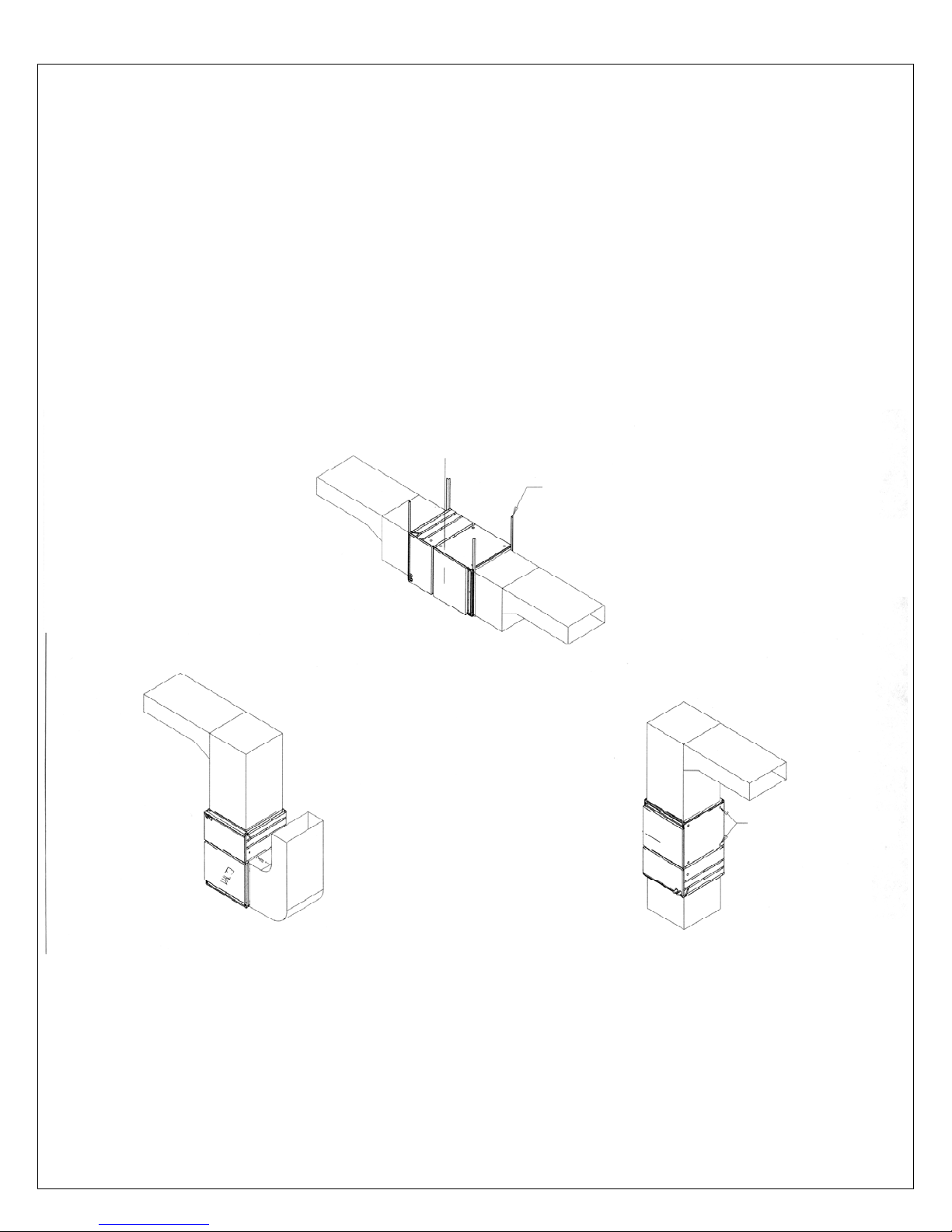
For horizontal installations, it is recommended to use s
rods supporting the unit from the bottom. Refer to Figure 1.
teel angle support brackets with threaded
4
Due to the hazardous nature of electrical and mechanical requirements only trained and
materials
.
Return air knock out.
qualified personnel should install and service heating and cooling equipment.
WARNING
It is important to check airflow and make sure that the furnace does not operate above
the temperature rise specified in the specifications, Section 6. This is particularly
important if a cooling or heat pump coil has been installed. High limit thermal protectors
should never engage during normal operation of the furnace. The high limit protectors
are designed to engage during the improper functioning of the blower or when the air
has not been kept clean.
Fig 1
Horizontal Installation
Note : Return air opening must be cut out
to knockouts provided. Minimum return air
opening size, 18’’ X 18’’
Caution : Return air openings shall not be
installed in back panel.
Supply air plenum must be constructed of
suitable materials and sized by installing
contractor so as to be of sufficient strength
to support furnace and accessory fittings
and materials.
Minimum 1’’ x 1’’ x 1/8’’ angle
Note : Field selected suspension
materials must be sized by the installing
contractor and be of sufficient strength to
support air handler weight of 100 lbs and
connected accessory fittings and
fi
lter
Upflow Installation
Counterflow Installation
electing a location
S
This furnace shall be centrally located in relation to
the outlet registers. All ductwork shall be
suitably sized with external static pressure in mind to ensure adequate air distribution.
These furnaces are suited for vertical up flow, down flow an
d horizontal installations. This furnace
shall not be installed on its front or back. To install this unit on its front or back would result in
inadequate access for servicing. Always ensure that when suspending this furnace that suitable
structural support is available and provides adequate access to the control and fan
compartments for service.
5
 Loading...