

Page 1
Installation, Operation and
Service Manual
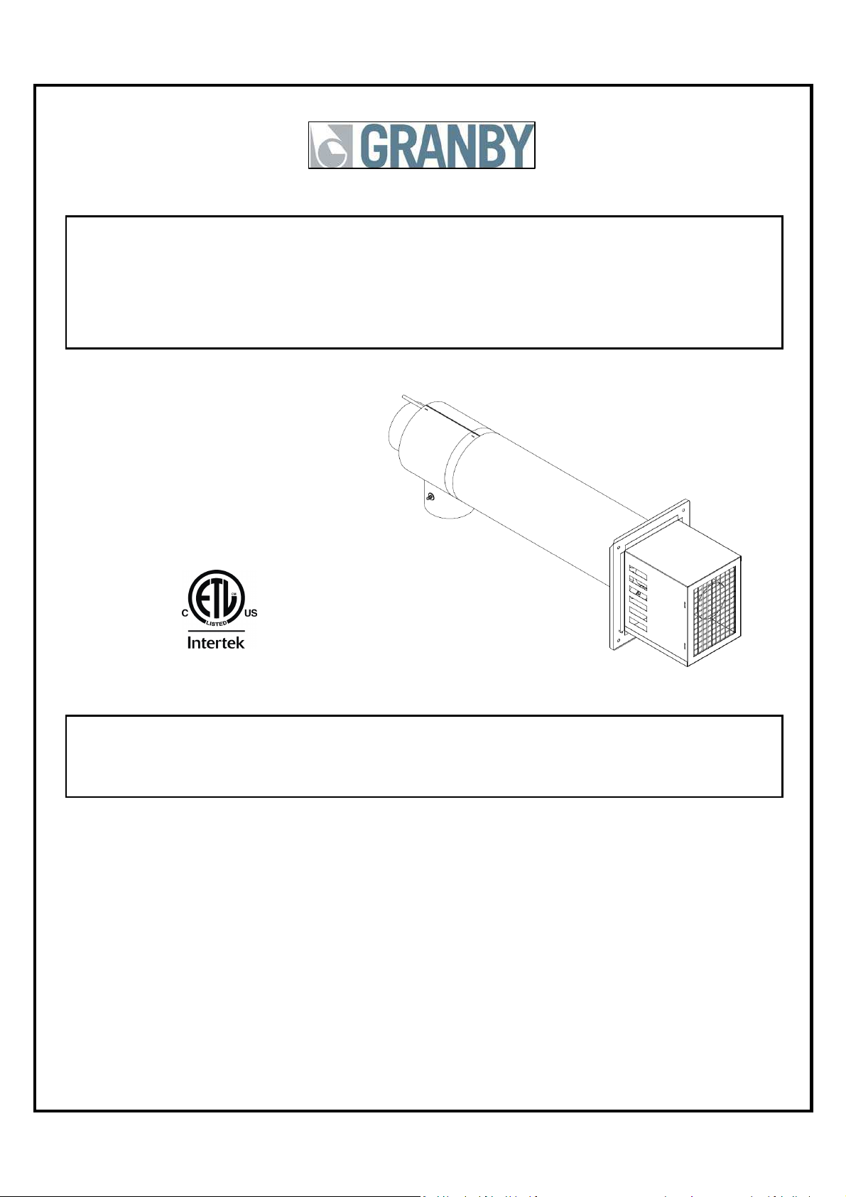
Direct Vent
CO-AXIAL DIRECT
VENT SYSTEM
Please read the manual in its entirety before beginning installation.
This manual must be kept with the direct vent system for future
GRANBY FURNACES INC.
PO Box 637
12118 Hwy 209
Parrsboro Nova Scotia Canada
B0M 1S0
902-254-2543
www.granbyindustries.com
DVS-100
INSTALLATIONS MUST MEET ALL LOCAL AND FEDERAL
CODES THAT MAY DIFFER FROM THIS MANUAL
reference.
10-25-2012
G2012-E4 Rev. C
Page 2

TABLE OF CONTENTS
1.0 IMPORTANT SAFETY ADVICE
2
2.0 APPROVED APPLIANCE
3.0 INSTALLATION REQUIREMENTS
4.0 CO-AXIAL VENT INSTALLATION PROCEDURE
5.0 INSTALLATION CONSIDERATIONS
6.0 DIRECT VENT RECOMMENDATIONS
7.0 TERMINAL INSTALLATION
8.0 FLUE PIPE ADAPTER INSTALLATION
9.0 FLUE PIPE CONNECTION
9.1 CONNECTION TO APPLIANCE 12
9.2 CONNECTION TO TERMINAL 12
10.0 COMBUSTION AIR PIPE INSTALLATION
3
3
5
5
6
6
9
12
13
11.0 PRESSURE SAFETY SWITCH INSTALLATION
12.0 PRESSURE SWITCH WIRING CONNECTION
12.1 KLR, KLF & KHM CONNECTION 15
13
15
12.2 CAST IRON BOILER B*C CONNECTION 15
13.0 HEATING UNIT BURNER SPECIFICATIONS
14.0 START-UP INFORMATION
16
18
14.1 START-UP PROCEDURE 18
14.2 COMBUSTION TEST 18
15.0 EXPLODED PARTS VIEW
19
1
Page 3
1.0 IMPORTANT SAFETY ADVICE
Please read and understand this manual before installing, operating or servicing the
DVS-100 direct vent system. To ensure you have a clear understanding of the operating
procedures of the DVS-100 direct vent system please take the time to read the IMPORTANT
SAFETY ADVICE section of this manual.
WARNINGS
NEVER store combustible material around it.
DO NOT attempt to start burner when excess oil has accumulated, or when unit is full of
vapors.
CAUTION
DO NOT START THE BURNER UNTIL ALL DVS DIRECT VENT SYSTEM PARTS,
ADAPTERS AND SILICONE SEALANT ARE IN PLACE. DO NOT TAMPER WITH THE
APPLIANCE OR CONTROLS, CALL A QUALIFIED BURNER TECHNICIAN.
IMPORTANT
This manual contains instructional and operational information for the DVS-100 direct vent
system. Read the instructions thoroughly before installing the DVS-100 direct vent . Consult
local authorities about your local FIRE SAFETY REGULATIONS. All installations must be in
accordance with local state or provincial codes. Improper installation will result in voiding of
warranty.
Please make sure that the DVS-100 sticker found in the installation, operation and
service manual is affixed on the furnace before/after the installation of the equipment to
certify installation of the DVS-100 with the appliance. If the sticker is already in place on
the heating appliance, please ignore this note.
2
Page 4
2.0 APPROVED APPLIANCE
The DVS-100 direct vent system is approved with the following heating equipment
manufactured by Granby Furnaces inc.:
• Warm air furnace KLR (small and large models) with input ranging from 0.55
USGPH to 1.15 USGPH.
• Warm air furnace KLF with input ranging from 0.75 USGPH to 1.10 USGPH.
• Warm air furnace KHM (small and large models) with input ranging from 0.55
USGPH to 1.15 USGPH.
• Cast Iron boiler model B*C with input ranging from 0.70 USGPH to 1.25 USGPH
The only approved burners for the DVS-100 system are Riello BF3 and BF5 burners.
BF3 burner: KLR-1 / 090 (up to 0.75 USGPH), KHM-1 / 090 (up to 0.75 USGPH) and the B*C
cast iron boiler 3 sections only.
BF5 burner: KLR-2 / 140 (up to 1.15 USGPH), KLF-140 (up to1.10 USGPH), KHM-2 / 140 (up
to 1.15 USGPH), Cast Iron boiler B*C (4 and 5 sections).
All burners are to be installed with nozzles and pump pressures as specified in this
manual and on the units rating plates specific to direct vent systems.
3.0 INSTALLATION REQUIREMENTS
The vent and combustion air intake must be installed in accordance to CSA B139/NFPA31 or
the appliance local codes. We do not recommend enclosing flexible vent pipe, nor having the
flexible vent pipe pass through interior walls, floors or ceilings. If the pipe passes through
walls, floors or ceilings the methods detailed in CSA B139/NFPA31 must be followed.
3
Page 5
WALL TERMINAL INSTALLATION REQUIREMENTS
In CANADA
Refer to the CSA B139 Code for the placement of the vent termination
In UNITED STATES
Refer to the NFPA31 Code for the placement of the vent termination
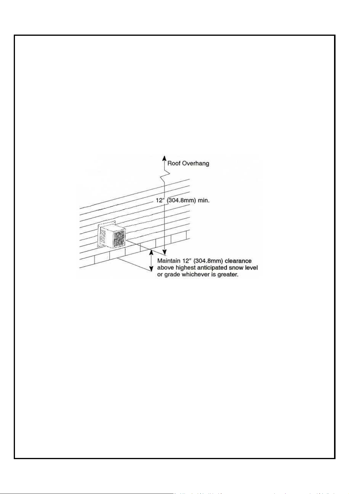
Direct vent terminal wall clearance
Outlet termination clearance above grade and roof overhang
VENT TERMINATION WARNING
It is the responsibility of the homeowner to ensure that the area
around the vent terminal and air intake is free of snow, ice and
debris. The vent terminal should be checked during heavy
snowstorms to ensure proper operation.
4
Page 6
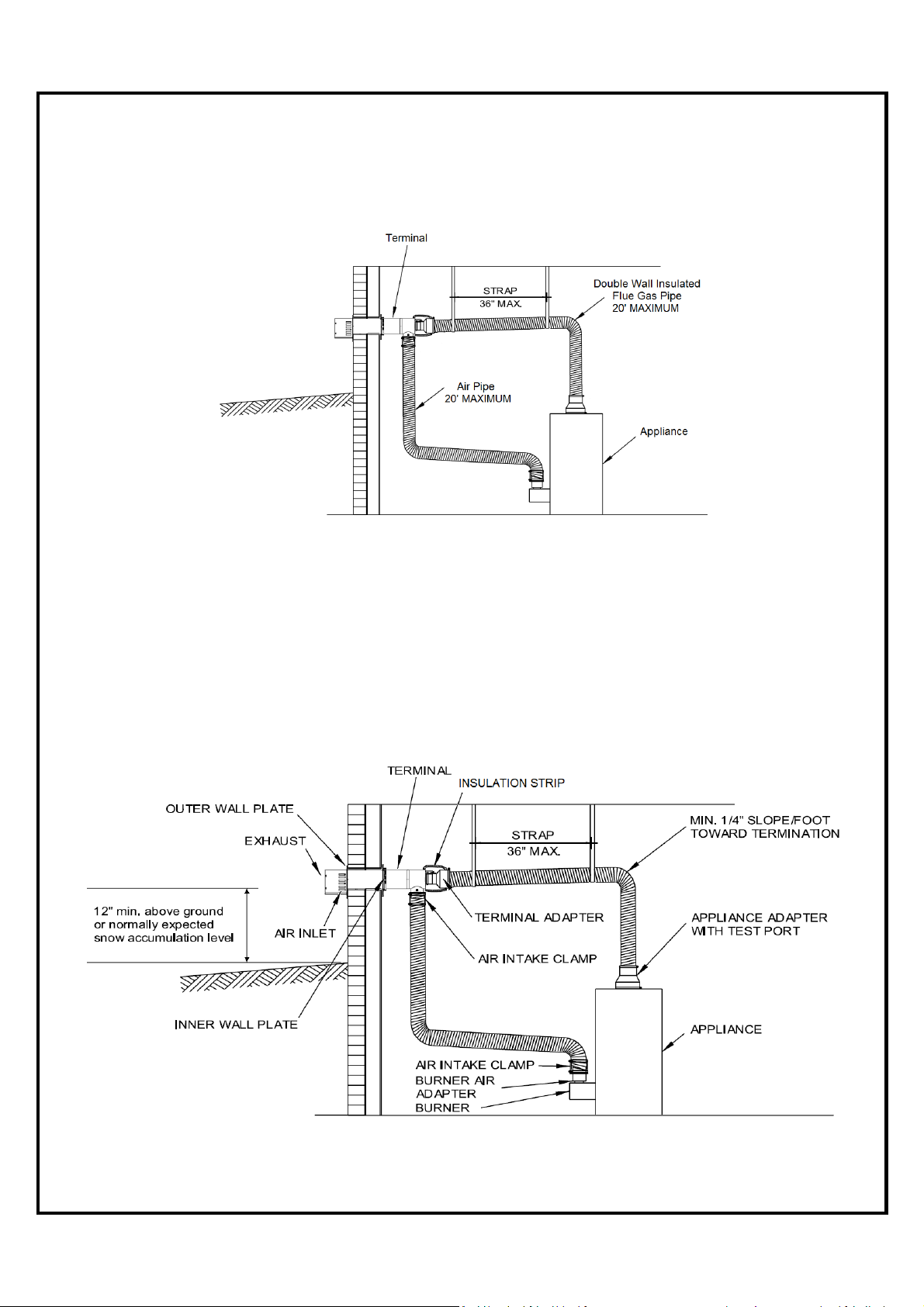
4.0 CO-AXIAL VENT INSTALLATION PROCEDURE
Only approved venting components shall be used. The maximum length of flue gas vent pipe
and air pipe is 20’ (6 m). The vent pipe must be in one continuous piece with no joints.
5.0 INSTALLATION CONSIDERATIONS
1. Place metal strapping every 36” to support vent pipe and prevent it from sagging.
2. Minimum wall thickness is 6’’ and maximum is 14’’.
3. This system is not designed for common venting. Use for a single appliance only.
4. Utilize the appliance adapter test port for combustion testing.
5. Follow national codes for the installation of DVS-100 equipment:
in USA – NFPA31, in Canada – CSA B139 and local regulations.
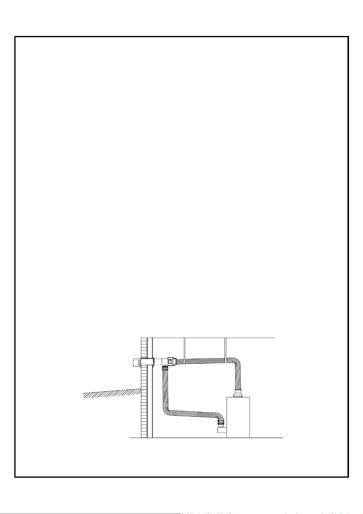
Direct vent system installation
5
Page 7
Wall
Terminal
Outer Wall
6.0
DIRECT VENT RECOMMENDATIONS
The following Direct Vent recommendations are based on data from the field and laboratory
testing.
a) The minimum inside bend radius for the vent is 12”.
b) The appliance must be located within the heated space.
c) The combustion air supply must not be insulated for the last 48” before the burner.
d) A combustion air damper kit is recommended for areas of extreme cold (-30OC).
e) Interior oil tanks are recommended.
f) The oil filter must never be placed outdoors.
g) The vent should be as short as possible with minimum bends.
h) The vent terminal should not be placed on the building exterior side facing high
prevailing winds.
i) In extremely cold climates, ice may have to be removed from the terminal on a regular
basis.
j) Natural wood and stucco exterior building finishes may be affected by exhaust gases.
7.0 TERMINAL INSTALLATION
Make sure you have all necessary components
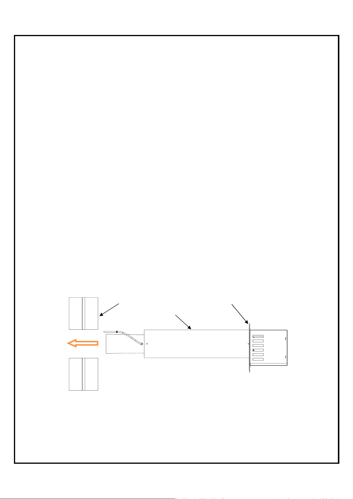
1. Determine the terminal location.
2. Cut a 6 1/4“ round hole through the wall (slightly larger than the O.D. of the terminal).
3. Remove the terminal air adapter from the termination.
4. From the outside of the building, insert the outer section through the hole until rests
against the wall. See figure 1.
Figure 1 – Terminal installation (Step 1 to 4)
6
Page 8
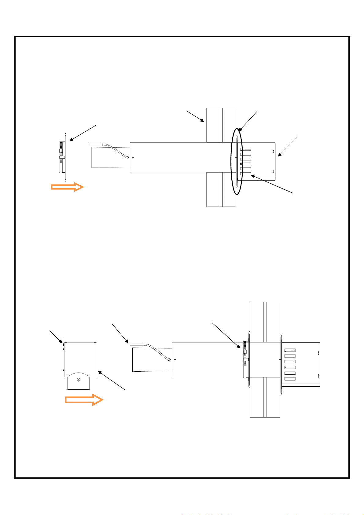
5. Seal with a weatherproof sealant around the edge of the outer wall plate to prevent
water from getting inside (figure 2). It is recommended that a 24” x 24” patio block be
placed under the vent terminal in areas where vegetation may grow up around the
terminal.
6. From the inside of the building, slide the inner wall plate over the outer section and
secure using four (4) screws. See figure 2.
Inner Wall Plate
Wall
Figure 2 – Terminal installation (Step 5-6)
Seal with
silicone
Exhaust
Air Intake
7. Tighten the collar around the terminal. (Figure 3)
8. Slide the terminal air adapter on the interior portion of the termination. Pay attention to
align the pressure tube inside the grommet mount on the terminal air adapter. See
figure 3.
Grommet
Pressure tube
Gear Clamp
Terminal Air Adapter
Figure 3 – Terminal installation (Step 7-8)
7
Page 9
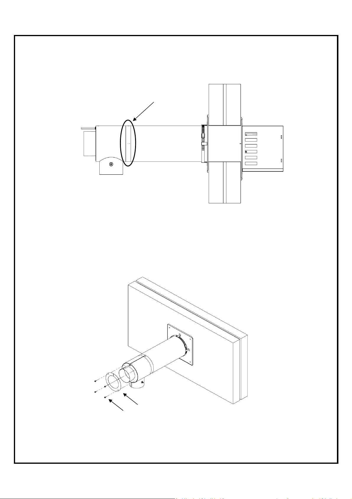
9. Seal with aluminum duct tape the joint between the terminal air adapter and the other
fixe tube of the terminal. See figure 4.
Seal with tape
Figure 4 – Terminal installation (Step 9)
10. Fixe the end cap plate to the end of the interior terminal using four (4) screws to secure
the inner pipe of the terminal.
End Cap Plate
Screw (4)
Figure 5 – Terminal installation (Step 10)
8
Page 10
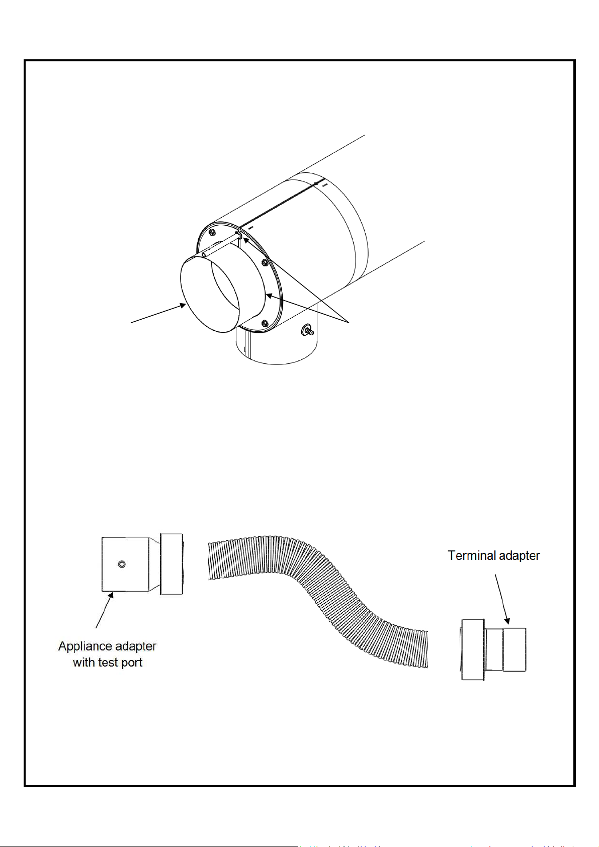
11. Seal with high temperature silicone (red) the gap between the end cap plate and the
inner tube. Also, seal around the grommet and the pressure tube.
Inner tube
Seal with silicone
high-temperature
Figure 6 – Terminal installation (Step 11)
8.0 FLUE PIPE ADAPTER INSTALLATION
9
Page 11
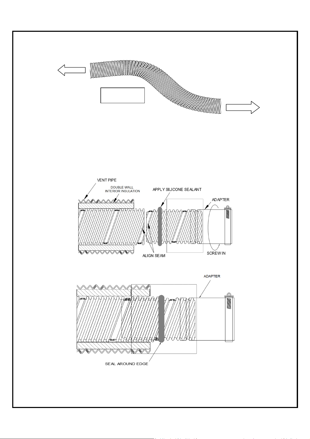
1. Pull the corrugated inner tube out of the vent pipe for easy access to insert the adapter.
Vent pipe
2. Apply silicone around the corrugated end of both appliance and terminal adapters.
3. Align the flat seams at the end of both corrugated tubes and insert the adapter into the
vent tube. Screw the adapter into the vent pipe with a counter clockwise motion. The
adapter should be fully inserted into the inner vent tube until it’s tight. The seams of the
tubes must be aligned for easy insertion. If the adapter does not completely screw into
the vent pipe, unscrew it and try again as per Step #3. Note that this is a multi-start left
hand thread: with one thread twice the width of the others. Therefore, care must be
taken to ensure that the correct threads are engaged before tightening in a counter
clockwise direction.
Figure 7 – Joint Assembly ( before insertion)
Figure 8 – Joint Assembly (insertion)
10
Page 12
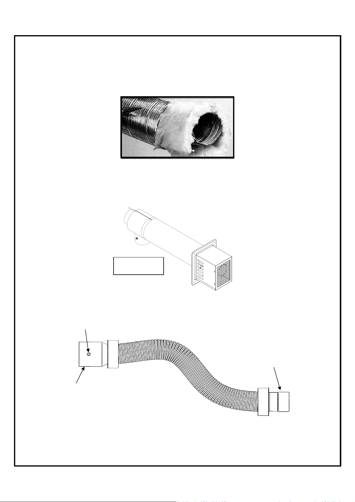
Terminal
4. If the vent area requires cutting to length, a fine-toothed hacksaw can be used. Remove
any burrs and flare out the end of the inner vent tube for easy installation of the adapter.
Ensure that there is enough length to form large radius bends no smaller than 12”
(0.3 m) in radius.
5. The vent must have 9” of clearance to combustibles within 36” of the appliance breech.
The remaining section of the vent to the terminal can have a minimum of 1” of clearance
to combustibles. The terminal is rated for 0 clearance to combustibles.
Terminal
Flexible double wall insulated flue gas pipe ready to be installed
Test port
Appliance
adapter with test
Figure 9 – Flexible flue gas pipe
11
Page 13
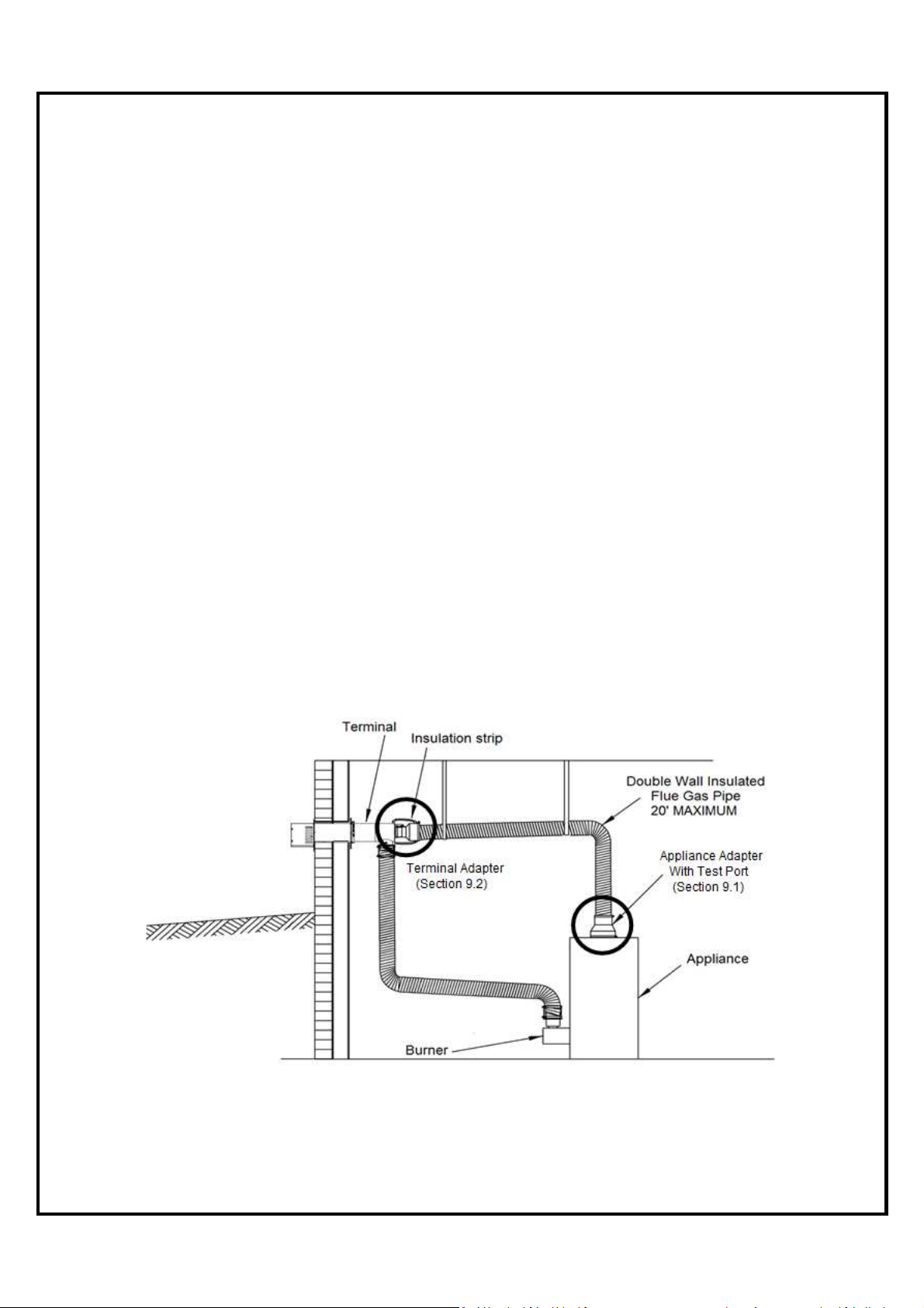
9.0 FLUE PIPE CONNECTION
9.1 CONNECTION TO APPLIANCE
1. Apply sealant around the appliance flue collar.
2. An approved appliance elbow may be used.
3. Slide the appliance adapter over the appliance flue collar.
4. Tighten the gear clamp of the appliance adapter around the flue collar (do not over
tighten).
A 5” appliance elbow is available to accommodate tight flex pipe connections to the appliance
where a 90 degree turn is required at the breech connection.
9.2 CONNECTION TO TERMINAL
1. Apply sealant around the termination pipe.
2. Slide the terminal adapter over the terminal flue collar.
3. Tighten the gear clamp of the termination adapter around the termination pipe (do not
over tighten).
4. Install the insulation strip over the terminal adapter connection. Using aluminum duct
tape, seal, each end of the insulation strip to the air adapter tee and the insulated flex
pipe.
A 4” terminal elbow is available to accommodate tight flex pipe connections to the terminal
where a 90 degree turn is required at the termination.
Figure 10 - Connection to appliance and terminal
12
Page 14
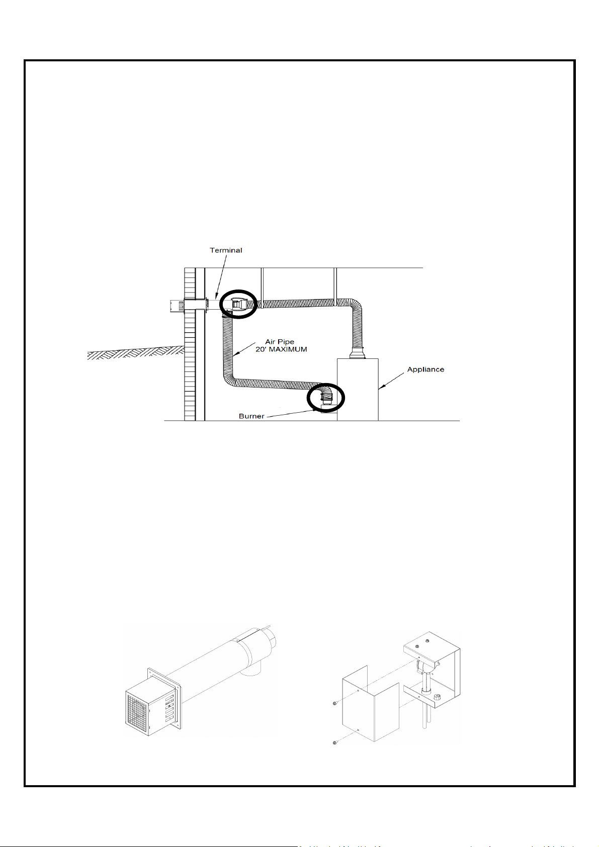
10.0 COMBUSTION AIR PIPE INSTALLATION
1. Use 4” diameter vent pipe ( not included in the DVS-100 kit ) for combustion air.
(The direct vent system requires additional parts. The combustion air pipe must
be approved, Schedule PVC 40, PVC-SWV, SDR-21, SDR-26, Septic Sewer Pipe,
ABS plastic pipe and aluminum pipe). Choice of material is up to the installer’s
discretion.
2. Run from the vent terminal to the burner.
3. A reducer will be required at the burner.
4. Seal all joints with sealant and / or aluminum duct tape.
Figure 11 – Combustion air pipe
11.0 PRESSURE SAFETY SWITCH INSTALLATION
Oil-fired appliances installed with a direct vent system requires a pressure safety switch. A
safety switch is included with the direct vent kit. It is the installer’s responsibility to install the
pressure switch in accordance with the instruction provided.
The pressure switch will automatically shut down the burner if vent is blocked for any reason.
Once the blockage is removed, the burner will automatically restart.
Pressure switch box must be installed in the vertical position on the inside wall near the
terminal
.
Pressure switch
Terminal
13
Page 15
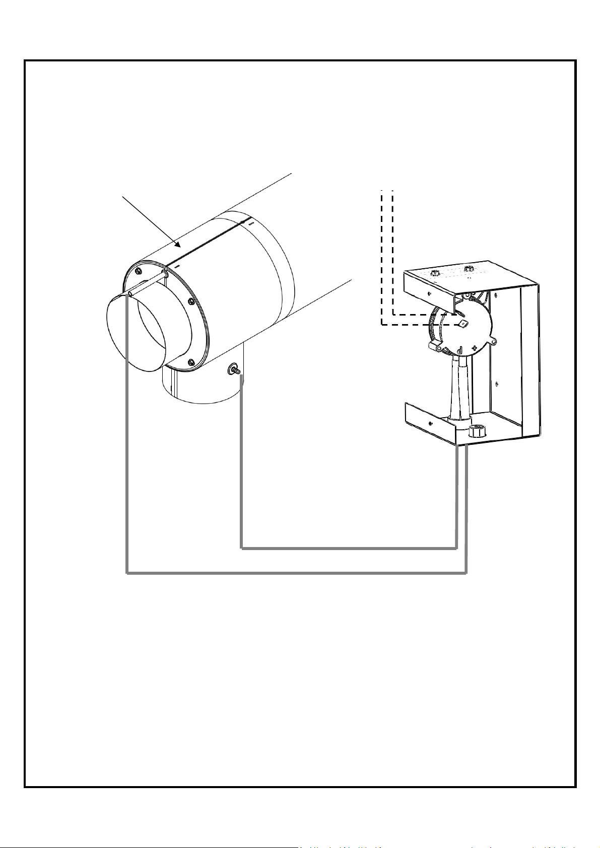
+ P
- V
Flue outlet
Air intake port
Terminal a
ir
Pressure (+)
adapter tee
port
Pressure switch connection to terminal
The pressure switch must be wired in series
with the thermostat and the control of the
appliance. For more information, see page 15
Vacuum ( - )
Port (- V) of the pressure switch
must be connected to the air intake
port on the terminal air adapter tee
Port (
must be connected to the flue
outlet terminal air adapter tee
Vacuum
) of the pressure switch
Pressure
+ P
Note:
Check flue and combustion air pipes for any leaks
PIPES CHECK
14
Page 16
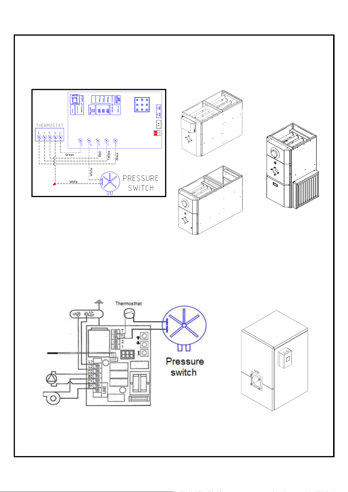
12.0 PRESSURE SWITCH WIRING CONNECTION
12.1
KLR, KLF and KHM WIRING CONNECTION
Honeywell ST9103
(Fan timer control)
KLR
KLF
KHM
12.2
B*C WIRING CONNECTION
Honeywell L7248 Aquastat
CAST IRON BOILER B*C CONNECTION
15
Page 17
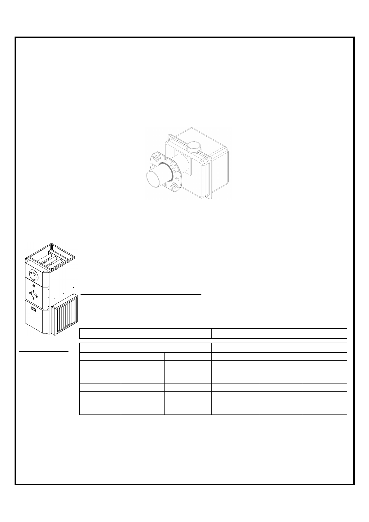
KHM
-
1 /
090
KHM
-
2 /
140
Riello Burner
BF3 BF5
Air Gate Adjustment
13.0 HEATING UNIT BURNER SPECIFICATIONS
1. Mount the burner to the heating unit using all four (4) mounting stubs. This will secure
the burner to the heating unit providing an even seal around the burner gasket
2. The wires leading from the burner housing must be sealed with the wire seal provided.
Riello BF sealed burner
KHM Series specifications
Unit Model
Firing Rate (USGPH) 0.55 0.65 0.75 0.90 1.05 1.15
Input (BTU/h) 77,000 91,000 105,000 126,000 147,000 161,000
Output (BTU/h) 67,000 79,000 91,000 109,000 126,000 139,000
Nozzle 0.40 70A 0.60 70W 0.65 70W 0.75 80W 0.85 70W 1.00 70W
Pump Pressure (psi) 190 145 145 145 165 145
Turbulator Setting 0 0 0 0 1 2
KHM-E1-*067-03 KHM-E1-*079-03 KHM-E1-*091-03 KHM-E3-*109-05 KHM-E3-*127-05 KHM-E3-*139-05
1.75 2 2.35 2 2.25 2.25
16
Page 18
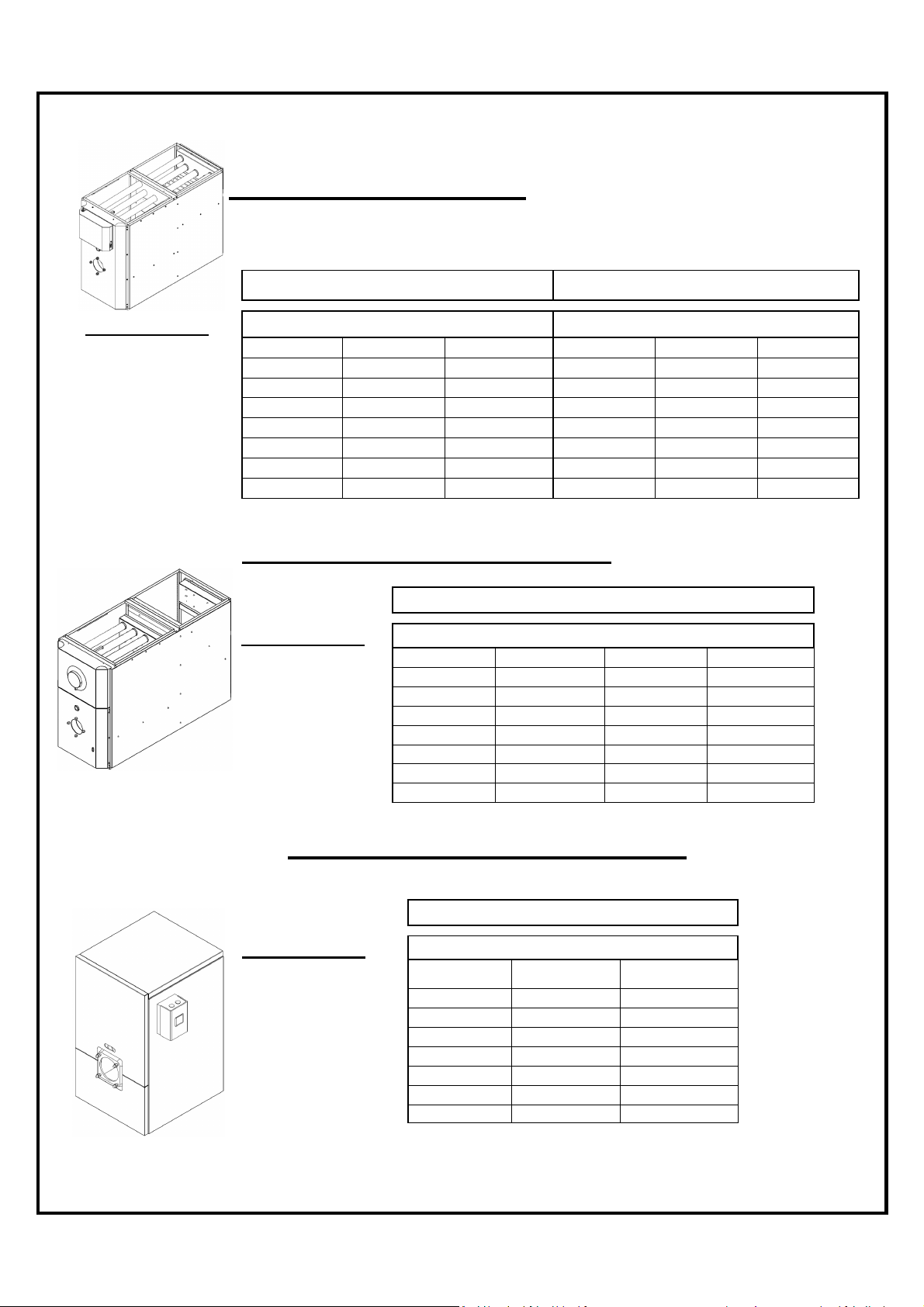
KLF
-
140
Air Gate Adjustment
Cast Iron Boiler
B*C-3 sections
B*C-4 sections
B*C-5 sections
KLR Series specifications
KLR-1 / 090 KLR-2 / 140
Riello Burner
Unit Model
Firing Rate (USGPH)
Input (BTU/h)
Output (BTU/h)
Nozzle
Pump Pressure (psi)
Turbulator Setting
Air Gate Adjustment
KLR-E1-*067-03 KLR-E1-*079-03 KLR-E1-*091-03 KLR-E3-*109-05 KLR-E3-*127-05 KLR-E3-*139-05
0.55 0.65 0.75 0.90 1.05 1.15
77,000 91,000 105,000 126,000 147,000 161,000
67,000 79,000 91,000 109,000 126,000 139,000
0.40 70A 0.60 70W 0.65 70W 0.75 80W 0.85 70W 1.00 70W
190 145 145 145 165 145
0 0 0 0 1 2
1.75 2 2.35 2 2.25 2.25
BF3 BF5
KLF Front breech specifications
Riello Burner BF5
Unit Model
Firing Rate (USGPH) 0.75 0.85 1.00
Input (BTU/h) 105,000 119,000 140,000
Output (BTU/h) 93,000 102,000 119,000
Nozzle 0.65 70W 0.75 70W 0.85 70W
Pump Pressure (psi) 145 145 165
Turbulator Setting 0 0 1
KLF-E3-*093-03 KLF-E3-*102-05 KLF-E3-*119-05 KLF-E3-*132-05
1.75 2 2.25
1.10
154,000
132,000
1.00 70W
145
2
2.25
B*C Cast Iron Boiler specifications
Riello Burner BF3 BF5 BF5
Unit Model
Firing Rate (USGPH) 0.70 1.00 1.25
Input (BTU/h) 98,000 140,000 175,000
Output (BTU/h) 83,000 121,000 151,000
Nozzle 0.55 70B 0.85 60B 1.00 60W
Pump Pressure (psi) 160 140 156
Turbulator Setting 2.0 1.0 2.0
Air Gate Adjustment 4.6 4.4 5.6
17
Page 19
14.0 START-UP INFORMATION
14.1 START-UP PROCEDURE
- Prior to start up make sure the service switch is in OFF position.
- Check all connections on the Direct Vent System between the terminal vent and
the appliance.
- Check to insure that clean quality #1 or #2 heating oil has been used to fill up your
storage tank.
- Open all manual shutoffs oil valves throughout the system.
- Follow the burner specifications in the instruction manual of the appliance for
proper setting, using accurate combustion test equipment, set the burner for proper
« steady state » operation. The use of accurate instruments is necessary to
achieve maximum efficiency and lowest fuels costs.
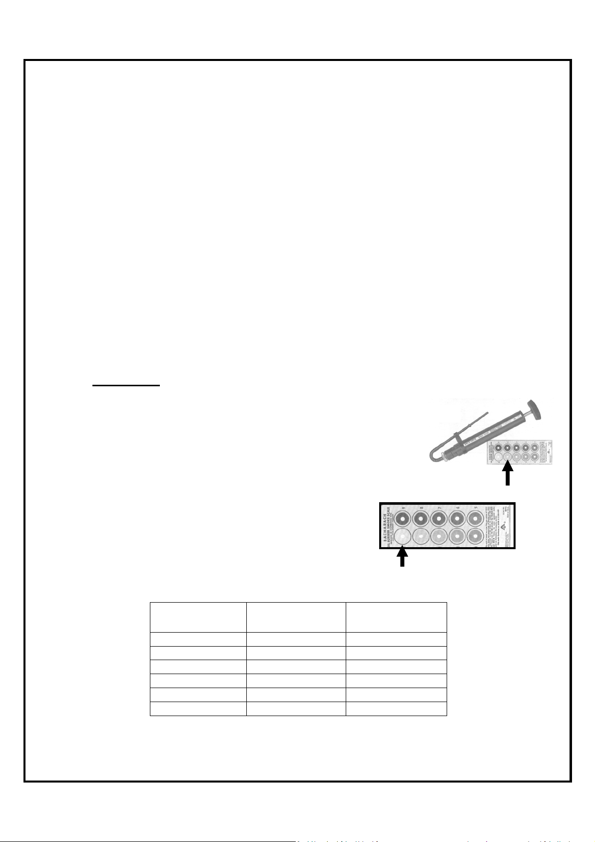
14.2 COMBUSTION TEST
Important: All your tests must be done with the burner cover on
1) After a minimum of 10 minutes of burner operation, take a
smoke test and adjust the burner to obtain a reading of
« 1 » on the smoke scale.
2) Take a CO2 Test and note the result
3) Open the air adjustment band on the burner
to reduce your CO2 lecture by 1.5%. You now
have a perfect « 0 » of smoke.
Relation between % of CO2 and O2
CO
(%) O
2
13.5 2.6 15.0
13.0 3.3 20.0
12.5 4.0 25.0
12.0 4.6 30.0
11.5 5.3 35.0
11.0 6.0 40.0
(%) Excess Air (%)
2
18
Page 20
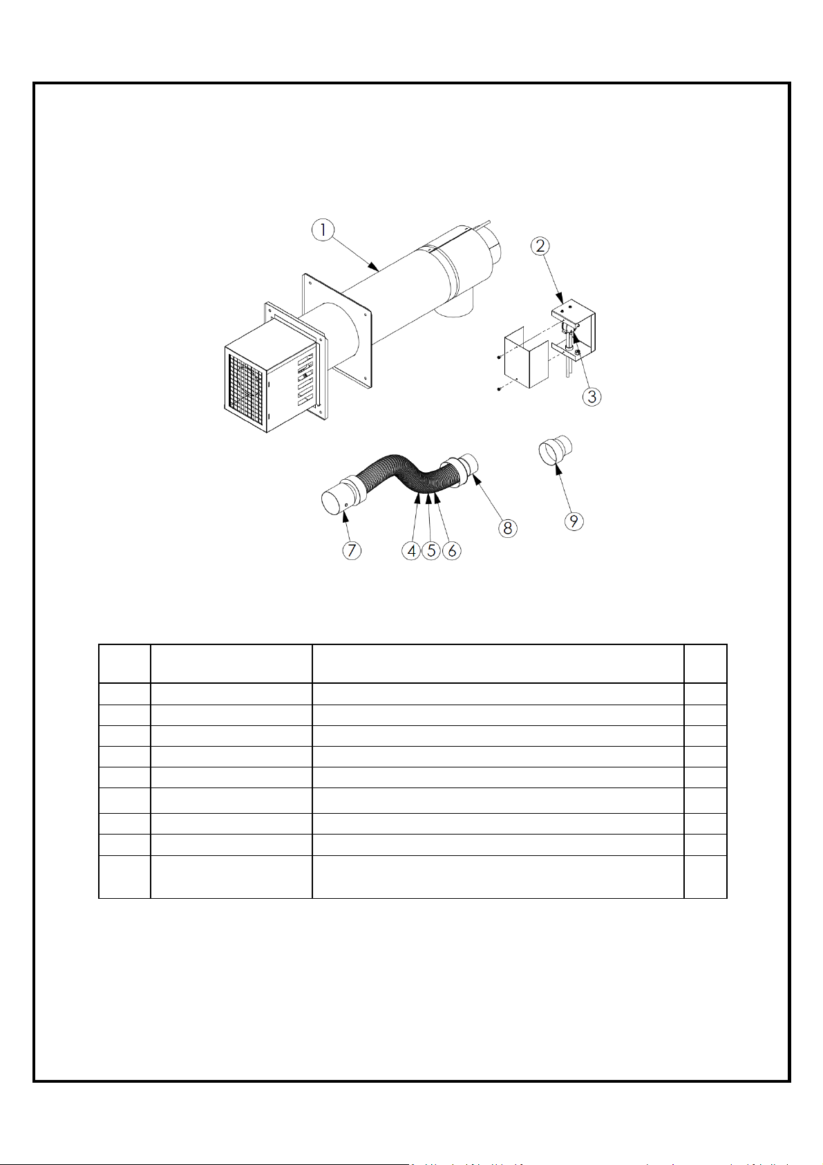
15.0 EXPLODED PARTS VIEW
DVS-100 Exploded Parts View
DVS-100 Part List
ITEM PART NUMBER DESCRIPTION QTY
1 DVT-A0-0002-00 Direct Vent Assembly 1
2 DVT-A0-0003-00 Pressure Switch Box Assembly 1
3 DVT-A0-0005-00 Pressure Switch 0.35’’ WC Assembly 1
4 3DV-FM-KIT4-00 Kit Direct Vent 4" X 10' 1
5 3DV-FM-KIT4-01 Kit Direct Vent 4" X 15' 1
6 3DV-FM-KIT4-02 Kit Direct Vent 4" X 20' 1
7 3DV-FM-ADAP-04 CERAFLEX 5" to 4" appliance adapter 1
8 3DV-FM-ADAP-03
9
(The direct vent system (DVS-100) requires additional parts. The combustion air pipe
must be approved, Schedule PVC 40, PVC-SWV, SDR-21, SDR-26, Septic Sewer Pipe,
ABS plastic pipe and aluminum pipe). Choice of material is up to the installer’s
discretion.
3DV-00-ADAP-00
CERAFLEX 4" to 4" terminal adapter 1
3" to 4" Air Inlet adapter for RIELLO- BF burner
Not included in kit
1
19
Page 21
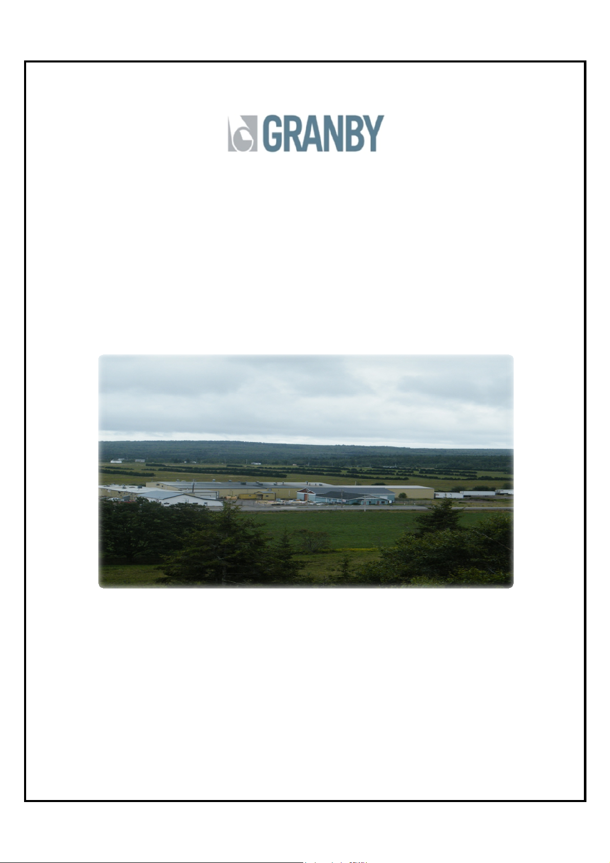
Granby Furnaces Inc. manufactures a full line of oil-fired furnaces
in its 70,000 square feet facility. Granby products are sold across
Canada and the United States through a distribution network.
Our team of engineers, designers and technicians continually
research and develop products to go beyond the demanding
specifications of today’s certifications.
Thank you
Thank you for choosing Granby
Thank you Thank you
for choosing Granby....
for choosing Granbyfor choosing Granby
20
 Loading...