

Page 1

Comet 145
OIL FIRED HOT WATER BOILER
Installation, Operation and
Maintenance Manual
INSTALLATIONS MUST MEET ALL LOCAL AND FEDERAL
CODES THAT MAY DIFFER FROM THIS MANUAL
Please read this complete manual before beginning installation. These instructions must be kept with
the boiler for future reference.
CERTIFIED TO: CAN/CSA Std. B140.0 & Std. B140.7
CONFORMS TO: UL 726
GRANBY FURNACES INC
PO Box 637
12118 Hwy 209
Parrsboro Nova Scotia Canada
B0M 1S0
www.GranbyIndustries.com
Page 2

COMET 145 – INSTALLATION/OPERATION MANUAL
TABLE OF CONTENTS
1.0 Homeowner Information 3
1.1 Introduction 3
1.2 Regular Maintenance 3
1.3 Warnings 3
1.4 Direct Vent 3
1.5 Shutting Boiler Down 3
1.6 Restarting Boiler 4
2.0 Installation 4
2.1 Important 4
2.2 Caution 4
2.3 General Instructions 4
2.4 Placement & Venting 4
2.5 Boiler Configuration 5
2.6 Assemble Boiler 5
2.7 Domestic Hot Water 6
2.8 Assemble & Install Burner 6
2.9 Set Burner for Efficient Operation 6
3.0 Oil Tanks & Piping 7
4.0 Boiler Return Water Temperature 7
5.0 Cabinet Assembly 7
6.0 Cleaning Instructions 8
7.0 Burner Specifications 9
8.0 Blocked Vent Switch 9
9.0 General Specifications 10
5IM-OB-COM0-00
Mar/11
1
Page 3

COMET 145 – INSTALLATION/OPERATION MANUAL
10.0 Appendix
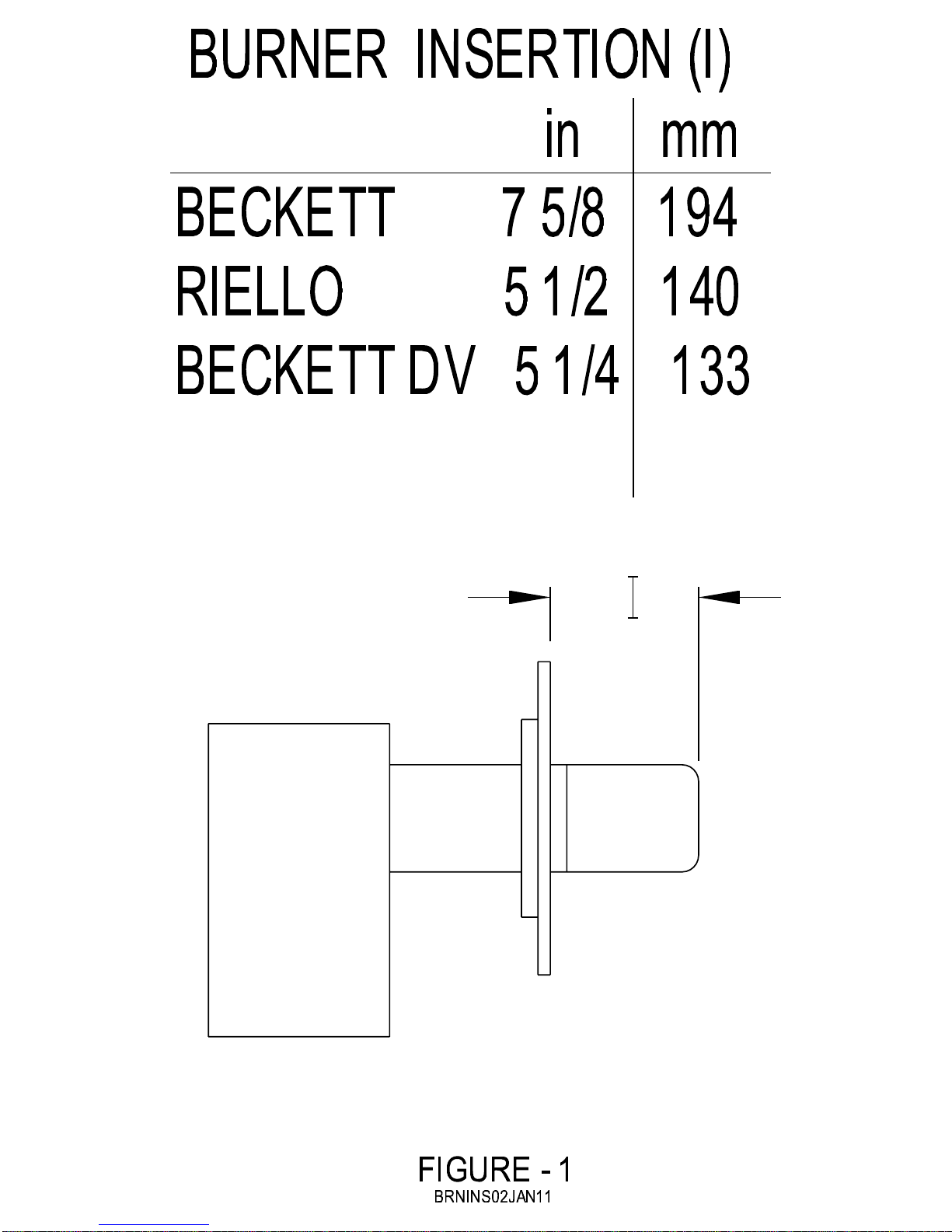
Figure – 1 Burner Insertion
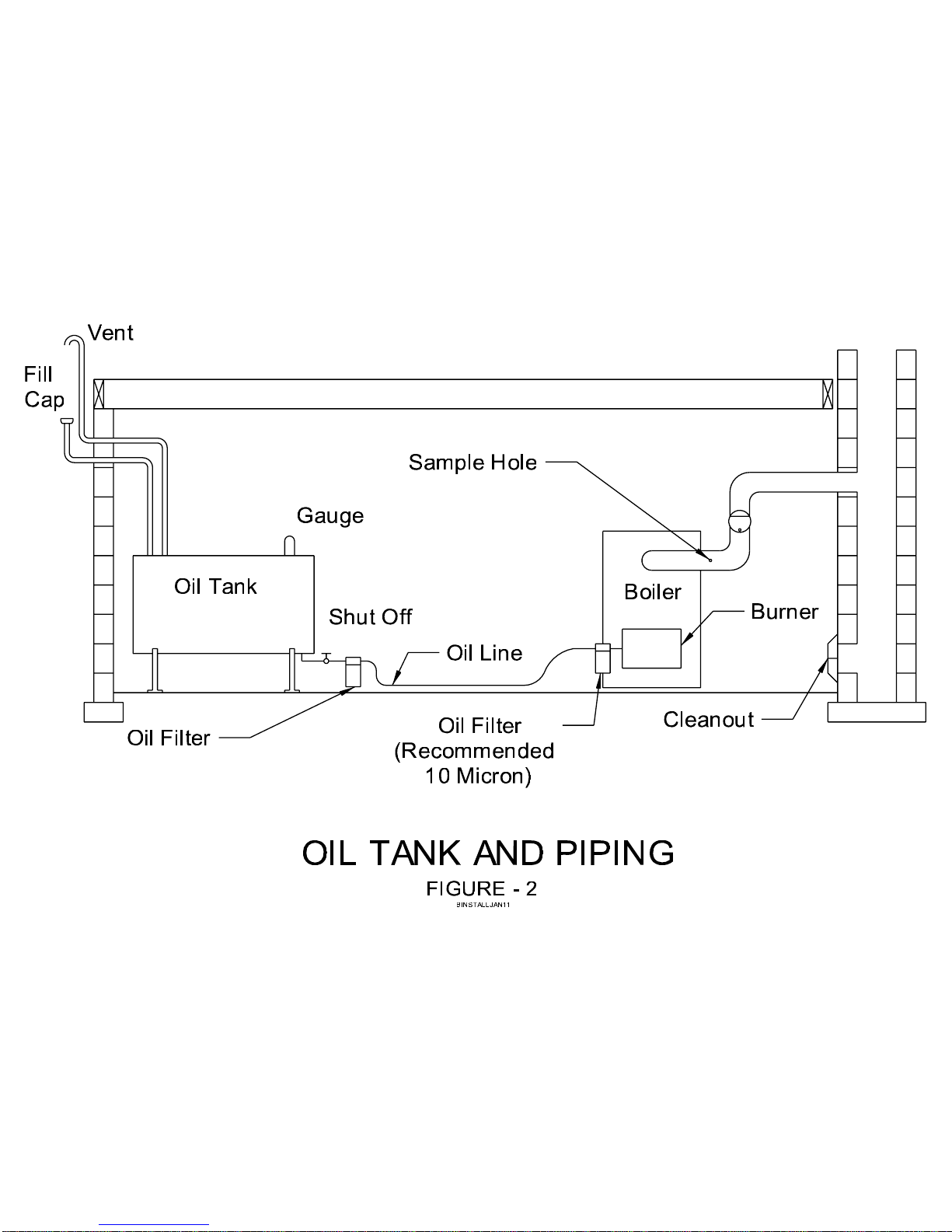
Figure – 2 Oil Tank & Piping
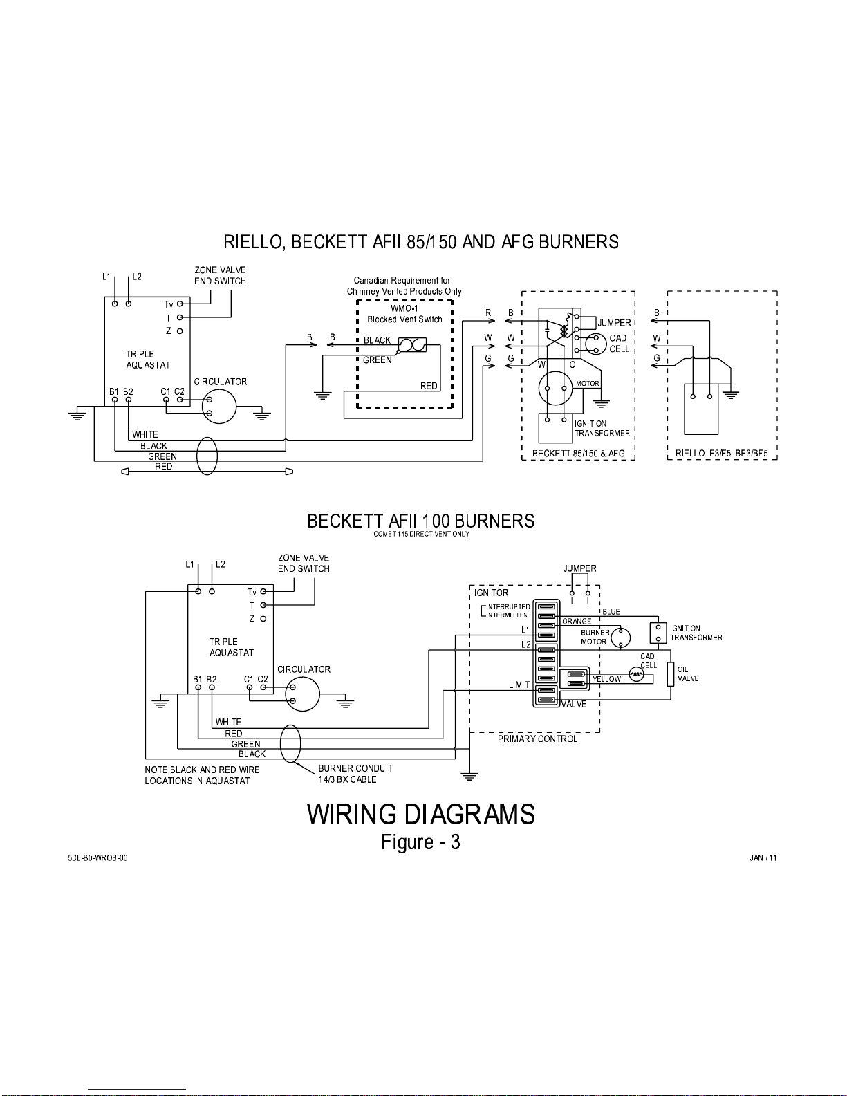
Figure – 3 Wiring Diagram
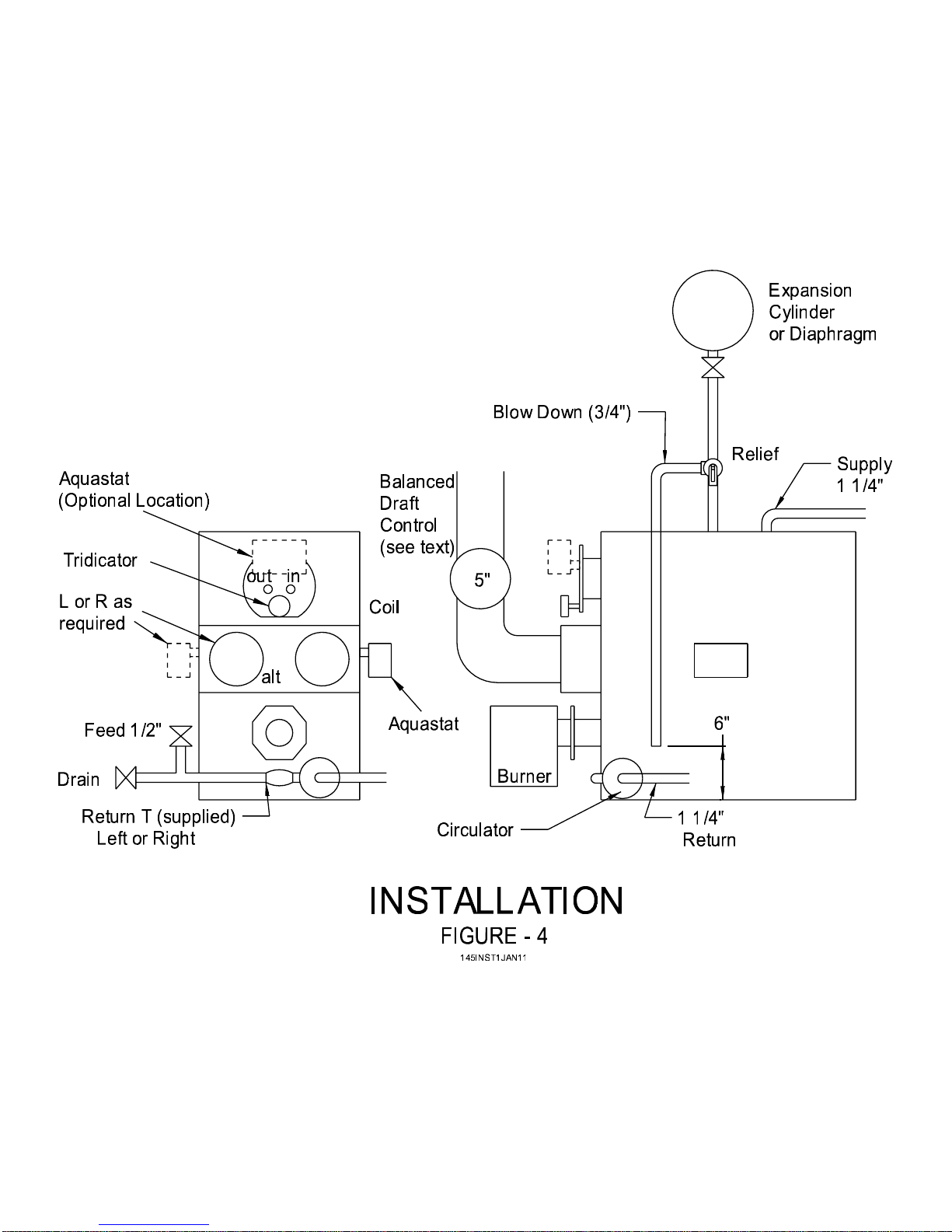
Figure – 4 Installation
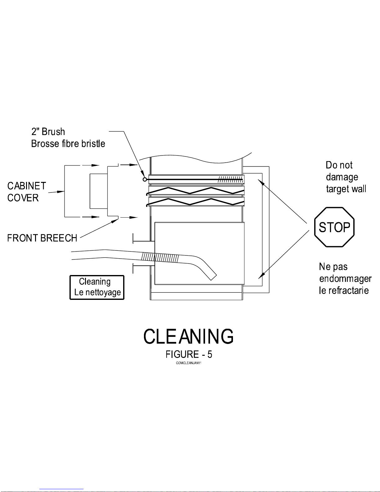
Figure – 5 Cleaning
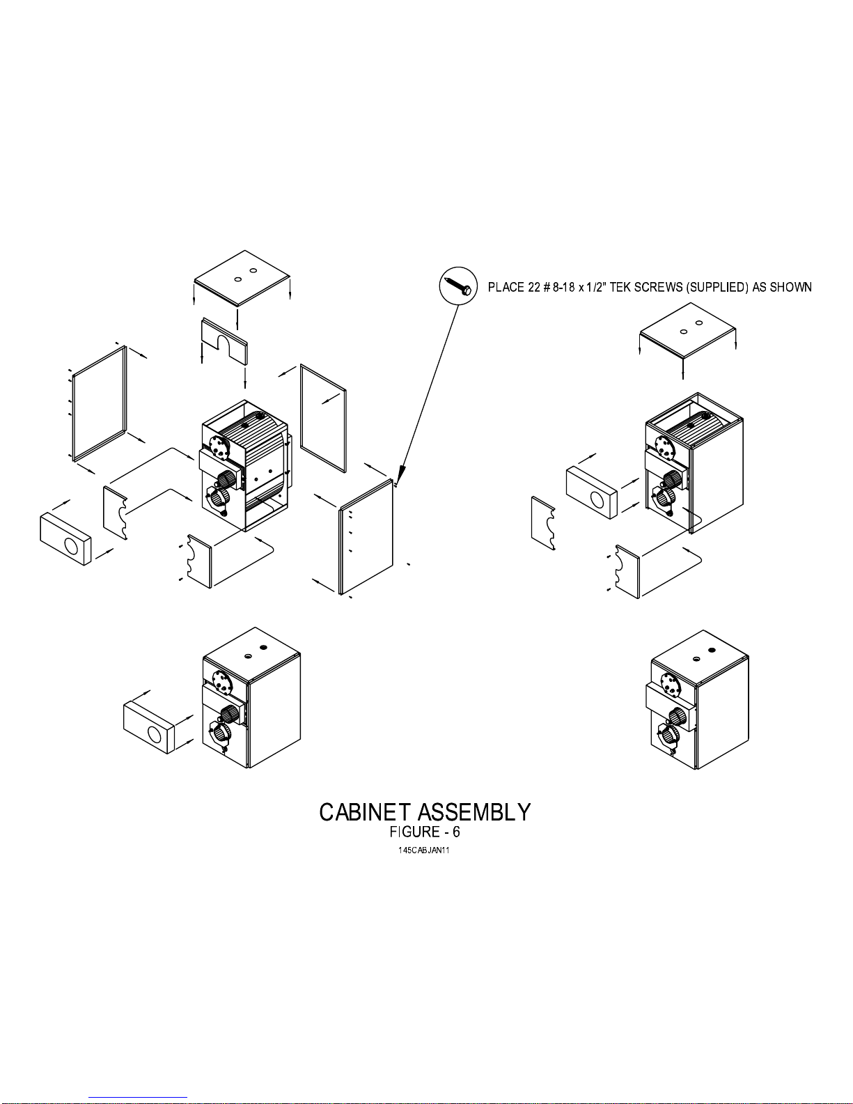
Figure – 6 Cabinet Assembly
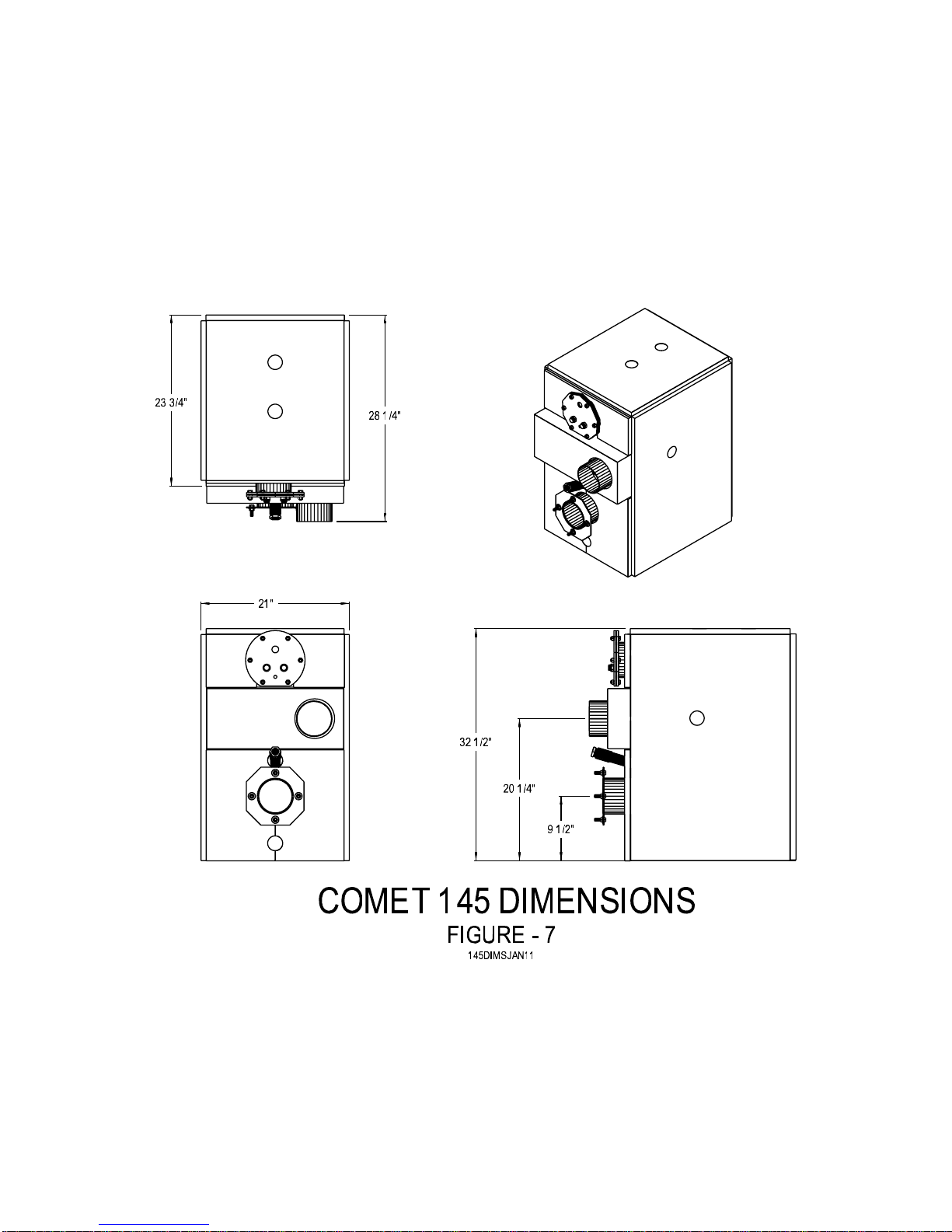
Figure – 7 Dimensions
Figure – 8 Exploded Parts
Table – 1 Parts List
Keep this manual in a safe place for future reference.
Follow manual carefully for the correct way to install and operate this appliance.
Do not operate this appliance until operating instructions have been read and fully understood.
SAVE THESE INSTRUCTIONS
5IM-OB-COM0-00
Mar/11
2
Page 4

COMET 145 – INSTALLATION/OPERATION MANUAL
1.0 HOMEOWNER INFORMATION
1.1 INTRODUCTION
Please read and understand this manual before installing, operating or maintaining the
boiler. To ensure you have a clear understanding of the operating procedures of the
appliance please take the time to read section 1.0 HOMEOWNER INFORMATION.
1.2 REGULAR MAINTENANCE
Have a qualified technician check complete boiler operation at least once a year.
1.3 WARNINGS
DISCONNECT POWER SUPPLY AND SHUT OFF OIL BEFORE WORKING ON BOILER.
DO NOT ATTEMPT TO START BURNER WHEN EXCESS OIL HAS ACCUMULATED.
WHEN UNIT IS FULL OF VAPOUR OR COMBUSTION ZONE IS VERY HOT.
NEVER BURN GARBAGE OR PAPER IN THE UNIT, AND NEVER STORE COMBUSTIBLE
MATERIAL AROUND IT.
DO NOT USE GASOLINE, CRANKCASE DRAININGS OR ANY OIL CONTAINING
GASOLINE.
1.4 DIRECT VENT
It is the responsibility of the homeowner to ensure that the area around the Direct Vent
terminal and the air intake is free of snow, ice and debris. The vent terminal should be
checked during heavy snowstorms to ensure proper operation.
1.5 SHUTTING BOILER DOWN
POWER OFF Turn off main power.
FUEL OFF Shut off manual fuel supply valve.
Always keep the manual fuel supply valve shut off if the burner is shut down for extended
period of time.
5IM-OB-COM0-00
Mar/11
3
Page 5

COMET 145 – INSTALLATION/OPERATION MANUAL
1.6 RESTARTING BOILER
Follow this procedure before restarting a unit that has been shut down for an extended period.
INSPECTION Have the boiler/system serviced and inspected by a qualified technician.
FUEL Turn on fuel supply and check that there are no leaks.
POWER Turn on power switch and check that the boiler starts and operates as usual.
OPERATION If the boiler/system fails or operates in an unusual manner call your service
technician. If the burner fails to operate at any time, call a qualified burner
technician.
2.0 INSTALLATION
2.1 IMPORTANT
Read owner’s manual before installing boiler or lighting burner. Consult local authorities if in
doubt about local fire safety regulations. Improper installation will result in voiding of warranty.
2.2 CAUTION
INSTALLATION MUST COMPLY WITH REGULATIONS OF AUTHORITIES HAVING
JURISDICTION. DO NOT START THE BURNER UNTIL ALL FITTINGS, COVERS AND
DOORS ARE IN PLACE. DO NOT TAMPER WITH THE BOILER OR CONTROLS.
2.3 GENERAL INSTRUCTIONS
Open all boxes, except cabinet or cabinet box. Check contents against the packing slip. In
case of shortages or damage, notify the transportation company immediately.
2.4 PLACEMENT & VENTING
Installations should conform to CSA Standard B139 or NFPA31 the Installation Code for Oilfired Equipment.
FLOOR COMBUSTIBLE or NON-COMBUSTIBLE - Support boiler frame
above damp floor using a Granby Appliance Stand if required. 3/8”
bolts may be used for leveling (not supplied). Floor must be strong
enough to support the weight of the boiler.
CHIMNEY & DRAFT Chimney/vent system must satisfy CSA B139, Installation Code. THE
BOILER MUST HAVE SUFFICIENT DRAFT AT ALL TIMES TO
ASSURE SAFE AND PROPER OPERATION. Not applicable for
Direct Vent.
TYPE “L” VENT Approved for Type “L” vent system. Maximum flue gas temperature of
575°F.
5IM-OB-COM0-00
Mar/11
4
Page 6

COMET 145 – INSTALLATION/OPERATION MANUAL
THROUGH-THE- Approved for use with the Granby Direct Vent and KPV -SS1C.
WALL VENTING
COMBUSTION & The B139 Installation Code requ ires the installer to provide sufficient
VENTILATION AIR outside air for ventilation. Always provide sufficient air to ensure safe
operation. See B139 for make up air requirements (Non-Direct Vent
only). Important for KPV-SS1C through-the-wall power vent system.
2.5 BOILER CONFIGURATION
L OR R BREECH To change, remove breech casing and breech. Rotate and replace.
Ensure gaskets are tight. See Figure – 4.
L OR R RETURN 1 1/4” x 1 1/4” return/drain Tee supplied in installation kit. May be
installed to give L or R return. See Figure – 4.
LEVELING BOLTS Install in base frame as required. This is an optional feature.
2.6 ASSEMBLE BOILER
CABINET See section 5.0 CABINET ASSEMBLY or Figure – 6.
OIL BURNER See section 2.8 ASSEMBLE & INSTALL BURNER.
AQUASTAT Honeywell L8124L1029 and White Rogers 8B43A-601 or certified
equivalent. For remote bulb, use Honeywell L8151A1052. The Triple
Aquastat can be located on the tankless coil or on either side of the
boiler. The openings not used for the triple aquastat must be sealed
with the pipe plugs provided.
CIRCULATOR As required.
DRAIN 1/2” IPS installs on return Tee.
TRIDICATOR Combination temperature and pressure indicator.
RELIEF VALVE Watts 335, 30 psig, ASME, 3/4” or equivalent.
BLOW DOWN Install 3/4” blow down termination within 6” of floor on relief valve
outlet. Blow down must contain no fittings that could prevent proper
operation. Must terminate in a SAFE PLACE.
EXPANSION TANK Diaphragm or cylinder as required.
FEED WATER Watts 1156 or equivalent, 1/2” IPS.
VALVE
DRAFT CONTROL 5” CSA approved or equivalent. Strong draft may require a larger
control. Attach the balanced draft control to the smoke/vent pipe as
shown in control instruction sheet. Not applicable for Direct Vent.
WIRING HARNESS Supplied with boiler installation kit, see Figure – 3.
5IM-OB-COM0-00
Mar/11
5
Page 7

COMET 145 – INSTALLATION/OPERATION MANUAL
VENT PIPE 5” Keep short with minimum of fittings. For chimney systems allow 1/4”
per foot rise to assist gas flow. See B139 Code and section 2.4
PLACEMENT & VENTING. Must not pass through ceiling.
PIPING 1 1/4” pipe for supply and return unless otherwise specified. Select L
or R as required. See Figure - 4.
2.7 DOMESTIC HOT WATER COIL
Use a K25m coil only. For best performance always connect cold water supply to RHS fitting
on coil.
ACTUAL FLOW & TEMPERATURE RATES MAY VARY FROM COIL SPECIFICATION
2.8 ASSEMBLE & INSTALL BURNER
ASSEMBLE Follow assembly and mounting instructions supplied by the burner
manufacturer.
END CONE See burner insertion settings in section 7.0 BURNER
SPECIFICATIONS or Figure – 1.
SELECT NOZZLE Select oil input, nozzle required and burner configuration to correspond
with boiler settings table shown on operating decal or section 7.0
BURNER SPECIFICATIONS.
INSTALL NOZZLE Install selected nozzle and make sure it is tight in the nozzle adapter.
ELECTRODES See burner manufacturer’s instructions.
INSERTION See operating decal or Figure – 1.
MOUNT BURNER Mount the burner and gasket on the boiler, inserting the burner head
through the opening in the front of the boiler. Tighten top nut first to
ensure burner tips slightly towards chamber.
WIRING See Figure – 3 or wiring decal.
2.9 SET BURNER FOR EFFICIENT OPERATION
END CONE See settings in section 7.0 BURNER SPECIFICATIONS.
BURNER AIR See settings in section 7.0 BURNER SPECIFICATIONS.
PUMP PRESSURE See settings in section 7.0 BURNER SPECIFICATIONS.
SAMPLING HOLE In vent pipe between boiler breech and draft control punch or drill a
1/4” diameter hole. Not applicable for Direct Vent.
DRAFT 0.04” WC Using an accurate draft meter; adjust the draft control to obtain 0.04”
wc of draft at the breech sampling hole. Not applicable for Direct Vent.
5IM-OB-COM0-00
Mar/11
6
Page 8

COMET 145 – INSTALLATION/OPERATION MANUAL
SMOKE TEST Adjust air control until a clean and symmetrical flame with “0-1” smoke
is obtained and then open to “0” smoke.
CO2 TEST CO2 should be 11 – 13% when burner is at “0” to trace smoke. If flame
will not clean up, replace nozzle.
TRIM BURNER AIR Always leave burner set at “0” smoke with CO2 reading about 1% of
CO2 lower than the peak efficiency achieved with a smoke trace (e.g.
12% CO2 should be set back 1% to 11%). This gives better allowance
for fuel and draft variations and maintains a better seasonal efficiency.
3.0 OIL TANKS & PIPING
Tank installation should conform to local requirements.
Install according to the applicable code. Minimize number of connections in suction line and
make all connections as tight as possible. Use a pipe joint compound suitable for oil on all
pipe threads. To reduce possibility of air leaks, tighten stem packing gland nut on any valves
installed in the suction line. Also, be sure the oil filter is tight, as filter gaskets often shrink.
Check for kinks in the oil lines as well as for possible air pockets and for loose connections.
Two filters as shown in Figure - 2 are recommended. Optional tank gauge protectors and
outlet protectors are available at your local dealer.
ONE PIPE SYSTEM Where the tank is above the burner and when the oil flows by gravity
to the oil pump, a single-stage fuel unit with a single oil line to the
pump may be used.
TWO PIPE SYSTEM When single line is unsuitable, use double line or see your dealer for
special oil line fittings.
4.0 BOILER RETURN WATER TEMPERATURE
Steel boilers are very susceptible to corrosion caused by condensation of flue gases. In order
to prevent this, the return water temperature must not fall below 140°F. Most hydronic
systems are designed for a delta T of 20°F. Therefore, the low limit should be set at no lower
than 170°F, which accounts for the -10°F differential of the triple aquastat. Heating systems
that require lower temperatures such as cast iron radiators and radiant systems require some
form of mixing device to ensure the return water is at or above 140°F.
The warranty will not be valid for steel boilers with return temperatures below 140°F.
For more information refer to B214-01 Installation Code for Hydronic Heating Systems
(or equivalent).
5.0 CABINET ASSEMBLY See Figure – 6
BOILER WRAP Wrap boiler with insulation, foil side out and secure with foil tape provided.
Cut holes for fittings as required.
SIDES & TOP Secure Left, Right and Top with sheet metal screws as shown.
REAR Attach Rear and secure with screws.
5IM-OB-COM0-00
Mar/11
7
Page 9

COMET 145 – INSTALLATION/OPERATION MANUAL
UPPER FRONT Carefully insert Upper Front around Coil and secure with screws.
LOWER FRONT Place split Lower Front Panel around view port, burner pipe and return
and screw as shown.
BREECH Secure Breech Cover with screws using #8 Tek screws provided (2 per
side).
6.0 CLEANING INSTRUCTIONS See Figure – 5
POWER OFF Turn off main power switch.
FUEL OFF Shut off manual fuel supply valve.
REMOVE CABINET Remove smoke/vent pipe from the boiler breeching collar.
COVER
REMOVE FRONT Remove breeching nuts, carefully loosen boiler breeching and lift off.
BREECH
REMOVE GAS Remove the flue gas baffles from the boiler tubes and clean them
BAFFLES using a wire brush.
REMOVE BURNER Make sure power and fuel are off.
CLEAN TUBES Clean the tubes carefully with a 2” fiber bristle brush. DO NOT
DAMAGE TARGET WALL.
VACUUM Vacuum out lower burner chamber.
REPLACE BURNER Check insertion is as specified. See Figure – 1.
REPLACE BAFFLES Replace flue gas baffles in tubes.
REPLACE BREECH Replace the boiler breeching and reseal against gaskets. New
gaskets can be obtained from your dealer. Attach with high
temperature silicone sealant. Secure with brass nuts and washers.
PANEL & PIPE Reinstall cabinet panel and reinstall smoke/vent pipe. Secure with
sheet metal screws.
CHECK Check installation before restoring power and fuel.
CHECK BURNER Smoke and CO2 test. Replace nozzle if required. Set burner for
efficient operation.
REAR COVER Do not remove rear cover for cleaning, as it is silicone sealed. If the
cover is replaced reseal with silicone.
WIRE BRUSH Use a wire brush to clean the inside of the vent connector pipe.
5IM-OB-COM0-00
Mar/11
8
Page 10
COMET 145 – INSTALLATION/OPERATION MANUAL
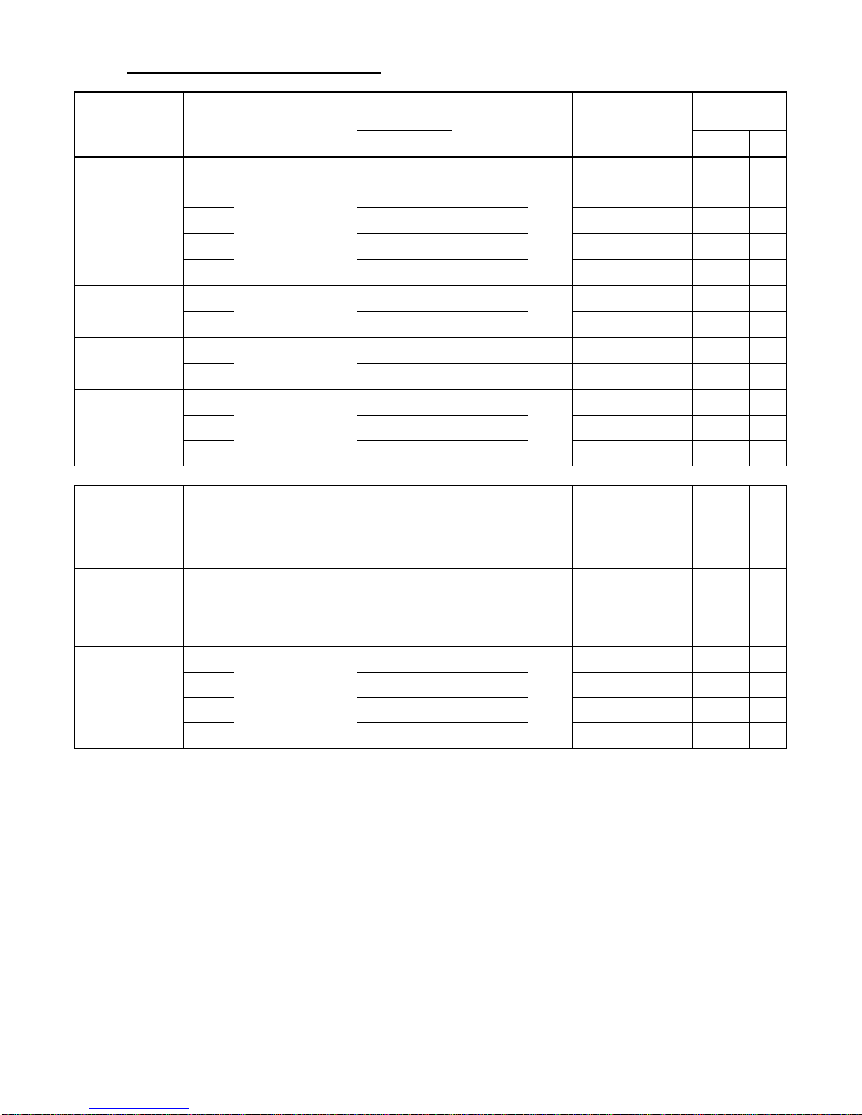
7.0 BURNER SPECIFICATIONS
Model ID # Burner
CE3-1
CE3-2 0.73 2.76 0.60 60W 3.50 1.5 88,000 26
BCF-E2-0125-10(15)
BCF-E4-0145-10(15)
BCF-B3-0095-10(15)
BCF-B2-0140-10(15)
Direct Vent
CE3-3 0.80 3.03 0.65 60W 3.70 2.0 96,000 28
CE3-4 0.92 3.48 0.75 60W 4.20 3.0 111,000 33
CE3-5 1.04 3.94 0.85 60W 5.00 3.0 125,000 37
CE5-1
CE5-2 1.22 4.62 1.00 60W 3.40 2.5 146,000 43
CB3-1
CB3-2 0.77 2.91 0.65 60A 140 4.75 pin 5 94,000 28
CB5-1
CB5-2 1.00 3.79 0.85 60B 7.00 pin 0 118,000 35
CB5-3 1.18 4.47 1.00 60B 7.50 pin 0 140,000 41
CV3-1
Riello 40 F3
Riello 40 F5
Beckett AFII – 85 -90*
Beckett AFII – 150 -90**
Input
Nozzle
USGPH L/h Btu/h kW
0.61 2.31 0.50 80B
1.04 3.94 0.85 60W
0.67 2.54 0.50 70B 180 4.00 pin 3 82,000 24
0.89 3.37 0.75 60A
0.61 3.48 0.50 80B
Pump
(psi)
150
150
140
Air
Setting
2.70 0.5 74,000 22
3.20 2.0 125,000 37
4.75 pin 0 107,000 31
4.10 1.00 74,000 22
Turbulator
Output
BCF-V2-0110-10(15)
BCF-V4-0145-10(15)
BCF-D8-0140-10(15)
CV3-2 0.73 2.76 0.60 60W 5.00 1.50 88,000 26
CV3-3 0.80 3.03 0.65 60W 5.60 2.00 96,000 28
CV5-1
CV5-2 1.04 3.94 0.85 60W 4.50 2.00 125,000 37
CV5-3 1.22 4.62 1.00 60W 5.50 2.50 146,000 43
CB1-1
CB1-2 0.89 3.37 0.75 60B 3.30 pin 5 107,000 31
CB1-3 1.00 3.79 0.85 60B 5.80 pin 6 118,000 35
CB1-4 1.18 3.94 1.00 60B 9.00 pin 8 140,000 41
Riello 40 BF3
Riello 40 BF5
Beckett AFII – 100***
0.92 3.48 0.75 60W
0.77 2.91 0.65 60B
150
4.00 1.50 111,000 33
150
6.60 pin 0 90,000 26
140
* Beckett AFII-85 – Air Tube HLX90HD (PA701)
** Beckett AFII-150 – Air Tube HLX90HC (PA601)
*** Beckett AFII-100 – Air Tube HLX90HB (PA901) post purge preset to 2 min.
The information provided by the manufacturer of this furnace supersedes any information
provided by any other party including the manufacturer of the burner.
5IM-OB-COM0-00
Mar/11
9
Page 11

COMET 145 – INSTALLATION/OPERATION MANUAL
8.0 BLOCKED VENT SWITCH
Oil-fired appliances installed in Canada require a blocked vent shut-off system when installed
on a chimney. A safety switch is included with the furnace to perform this function. It is the
installer’s responsibility to install the switch in accordance with the instructions provided. Not
applicable for Direct Vent or Power Vent systems.
Field Controls Model: WMO-1 (Manual Reset)
Switch Operation
Blocked vent switches are flue gas safety devices for detecting spillage of flue gases due to a blocked
flue or inadequate draft. After detecting a problem, the switch de-energizes the system’s burner
control.
NEVER reset the switch unless the cause of the blockage has been corrected.
Installation
1) Pierce a 5/8” hole in to the flue vent pipe near the appliance breech connection.
2) This hole must be at least 10” before the draft regulator, vertically or horizontally.
3) Remove one of the securing nuts from the threaded tube of the safety switch.
4) Tighten the other securing nut onto the pipe as far as possible.
5) Insert the threaded tube end into the pierced hole of the flue vent pipe.
6) Install the securing nut on the safety switch tube, which protrudes into the flue vent pipe.
Tighten the nut securely.
Wiring Instructions
Caution: Disconnect the electrical power when wiring the unit.
Wire the Blocked Vent Switch in accordance with The National Electrical Code and applicable local
codes. Wire the safety switch in series with the burner limit control or aquastat. Route the wiring with
an accepted wiring enclosure in accordance with the National Electrical code and applicable local
codes. Refer to wiring decal or Figure - 3.
System Test Procedure
1) With the power re-established, block the chimney or vent pipe downstream of the switch.
2) Adjust the thermostat to call for heat.
3) Once the heating system has started the blocked vent switch should shut down the
burner within 10 minutes or sooner.
4) Once the system has cooled, the blocked vent switch can manually be reset.
5) This procedure should be tested a second time.
6) After testing the blocked vent switch the chimney should be cleared of obstruction and the
heating system tested on a long run cycle.
If the block vent switch shuts down the system, check to ensure there is enough draft in the
chimney and venting pipes.
5IM-OB-COM0-00
Mar/11
10
Page 12

COMET 145 – INSTALLATION/OPERATION MANUAL
9.0 GENERAL SPECIFICATIONS
CLEARANCE TO COMBUSTIBLES
Top 6” (152 mm)
Front 24” (610 mm)
Rear - includes access 18” (457 mm)
Side (access) 2” (51 mm)
Side (access) 24” (610 mm)
Flue Pipe 9” (229 mm)
Floor Combustible or non-combustible
SMOKE/VENT See Code B139
Smoke/Vent 5” vent pipe, Type “L”
Chimney/Vent See B139 Code
Vent Systems KPV-SS1C Venter
Direct Vent
KPV-SS1C Settings
Certified for use with Type “L” Vent. Maximum flue temperature is 575°F.
DRAFT (non-Direct Vent only)
Breech Pressure -0.04” wc
CONTROLS
AQUASTAT Honeywell L8124L1029
L8124G1020
White Rodgers 8B43A-601
Erie Boss 2400 Series
Optional Remote Honeywell L8151A1052
RELIEF VALVE Watts 335, 30 psig ASME or equivalent
TRIDICATOR 70 psi/320°F or equivalent
BAROMETRIC 5” CSA Approved or greater
CLEANOUTS
Breech, burner opening
OIL INPUT
0.61 – 1.22 USGPH
2.31 – 4.62 L/h
FUEL No heavier than No. 2 furnace oil
DIMENSIONS
Overall depth, less burner 28 1/4” (1118 mm)
Cabinet depth 28 1/4” (1118 mm)
Cabinet height 32 1/2” (940 mm)
Cabinet width 21” (660 mm)
OPENING HEIGHTS
Burner center line 9 1/4” (235 mm)
Smoke pipe center line 20 1/4” (514 mm)
5IM-OB-COM0-00
Mar/11
11
Page 13

COMET 145 – INSTALLATION/OPERATION MANUAL
BURNER INSERTION
”
Beckett 7 5/8
(194 mm)
Riello 5 1/2” (140 mm)
Beckett DV 5 1/4” (133 mm)
WATER VOLUME
US gallons 19.55
IMP gallons 16.28
Liters 73.89
SPECIFICATIONS ARE SUBJECT TO CHANGE WITHOUT NOTICE.
FOR MOST RECENT UPDATES PLEASE VISIT www.GranbyIndustries.com.
The following form MUST be completed for the warranty to be valid.
Installed by:
Address:
Telephone: Date:
START UP TEST RESULTS
Nozzle: Pressure:
Air: Turbulator:
CO2: Smoke Number:
Breech Draft: Stack Temperature:
Test Performed By:
Staple Printout Here: Staple Smoke Spot Here:
5IM-OB-COM0-00
Mar/11
12
Page 14
Page 15
Page 16
Page 17
Page 18
Page 19
Page 20
Page 21
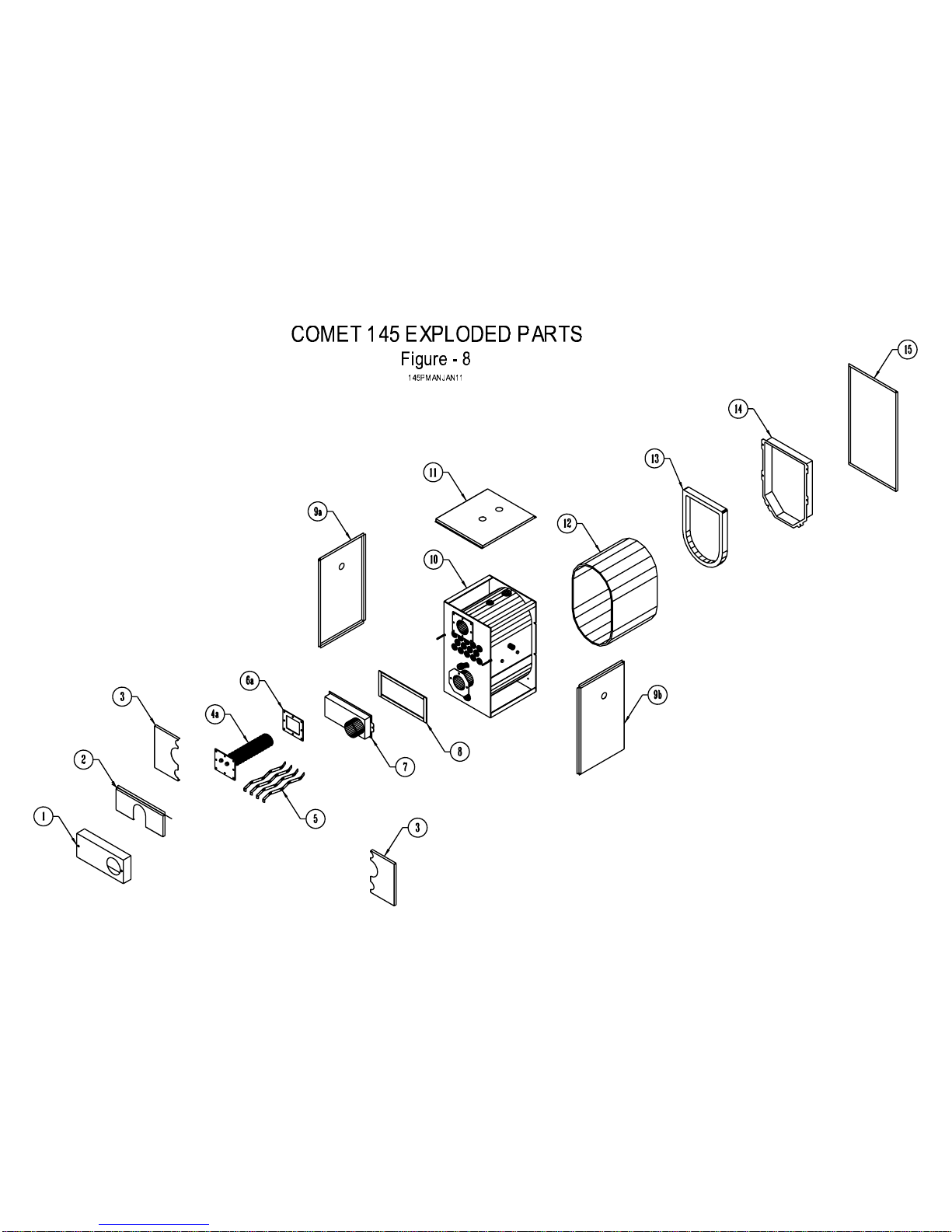
Page 22

Table - 1
Comet 145 Oil-Fired Boiler
Order No. Item No. Part Description
BC0-CB-0044-00 COMET 145-1 Cabinet Cleanout Cover
BC0-CB-0043-00 COMET 145-2 Cabinet Coil Cover
BC0-CB-0046-00 COMET 145-3 Cabinet Lower Front Cover (L/R)
3TC-05-K260-00 COMET 145-4A K26 Tankless Coil
3TC-05-K25M-00 COMET 145-4B K25m Tankless Coil (Round -Not Shown)
B00-PV-0424-00 COMET 145-5 Flue Gas Baffles
3GK-00-COIL-00 COMET 145-6A Coil Gasket for K26
3GK-00-COIL-01 COMET 145-6B Coil Gasket for K25m (Round -Not Shown)
BCF-PV-0020-00 COMET 145-7 Collector Cover
BC0-PV-0081-00 COMET 145-8 Collector Cover Gasket Set
BC0-CB-040A-00 COMET 145-9A Cabinet Side Panels (Left)
BC0-CB-040B-00 COMET 145-9B Cabinet Side Panels (Right)
BCF-PV-0010-00 COMET 145-10A Pressure Vessel Assembly
BCA-PV-0010-00 COMET 145-10B Pressure Vessel Assembly
BCF-CB-0110-00 COMET 145-11A Cabinet Top
BCA-CB-0110-00 COMET 145-11B Cabinet Top
BCF-CB-0010-00 COMET 145-12 Boiler Jacket
3CC-00-WALL-03 COMET 145-13 Target Wall
BCF-PV-0022-00 COMET 145-14 Rear Cover
BCF-CB-0130-00 COMET 145-15 Cabinet Rear Panel
4TD-00-PG75-00 COMET 145-16 Tridicator (Not Shown)
4AQ-00-L102-9B COMET 145-17 Aquastat L8124L1029B (Not Shown)
3BN-0F-3LBT-00 COMET 145-18 40F3 Riello (Long Tube)
3BN-0F-5LBT-00 COMET 145-19 40F5 Riello (Long Tube)
3BN-BF-3LBT-00 COMET 145-20 BF3 Riello Direct Vent (Long Tube)
3BN-BF-5LBT-00 COMET 145-21 BF5 Riello Direct Vent (Long Tube)
3BN-00-PA70-10 COMET 145-22 AFII-85-90 Beckett Burner PA #701
3BN-00-PA90-10 COMET 145-23 AFII-100 Beckett Burner DV PA #901
3BN-00-PA60-10 COMET 145-24 AFII-150-90- Beckett Burner PA #601
Please have serial number & date of manufacture ready when ordering parts
June-06
 Loading...