

Page 1

GRANBY CAST IRON SERIES
OIL-FIRED HOT WATER BOILER
BKC
Installation, Operation and
Maintenance Manual
INSTALLATIONS MUST MEET ALL LOCAL AND FEDERAL
CODES THAT MAY DIFFER FROM THIS MANUAL
Please read this complete manual before beginning installation. These instructions must be kept with
the boiler for future reference.
GRANBY FURNACES INC
PO Box 637
12118 Hwy 209
Parrsboro Nova Scotia Canada
B0M 1S0
www.GranbyIndustries.com
Page 2

GRANBY CAST IRON SERIES – INSTALLATION/OPERATION MANUAL
TABLE OF CONTENTS
General Instructions 1
Receiving Shipment 2
Clearances for Service & Combustible Materials 2
Combustion Air and Ventilation 3
Air for Combustion 3
Air for Ventilation 3
Combustion Air Supply with No Barometric Damper 3
Boiler Location & Leveling Of Unit 3
Burner Tube Insertion 3
Jacket Assembly 4
Piping 6
General Requirements for Piping Circuits 6
Circulation Pump 7
Controls/General 7
Piping Install Diagrams 7
Wiring 9
General Instructions 10
Typical Wiring Diagrams 10
Venting Requirements 10
Natural Draft Applications 11
Condensation 11
Fuel System 11
Boiler Series Specifications 12
Burner Specifications 13
Start Up Procedure 13
Maintenance and Testing-Serviceman 14
Testing Safety and Control Devices 14
Cleaning Boiler Sections 14
Cleaning Fuel System and Burner 14
Perform Combustion Tests 14
Parts List and Boiler Diagram 15
THE INSTALLATION OF THE EQUIPMENT SHALL BE IN ACCORDANCE WITH THE REGULATION
OF AUTHORITIES HAVING JURISDICTION AND CSA STANDARD B139
THE INSTALLATION OF THE UNIT SHALL BE IN ACCORDANCE WITH THE AUTHORITIES
HAVING JURISDICTION.
READ AND SAVE THESE INSTRUCTIONS FOR REFERENCE.
NOTICE: All installations must conform to federal, state and local code.
5IM-OB-CAST-00 May/11
1
Page 3

GRANBY CAST IRON SERIES – INSTALLATION/OPERATION MANUAL
CAUTION
DO NOT ATTEMPT TO START THE BURNER WHEN EXCESS OIL HAS ACCUMULATED,
WHEN THE UNIT IS FULL OF VAPOUR OR WHEN THE COMBUSTION CHAMBER IS
VERY HOT. NEVER BURN GARBAGE OR PAPER IN THE UNIT AND NEVER LEAVE
COMBUSTIBLE MATERIAL AROUND IT.
STEPS PRIOR TO INSTALLATION
Before beginning the installation process it is highly recommended that you read this manual
carefully. Your boiler must be installed by a qualified and where required licensed contractor in
accordance with all local codes. When local codes are not in effect the boiler must be installed
in accordance with NFPA 31 and NFPA 211, Standard for installation of Oil Burning Equipment
in the U.S. and CSA B139 in Canada. Failure to have the appliance installed by a qualified
technician in accordance with code may void your warranty.
Before installing the boiler inspect all items supplied by Granby for physical damage. Any
physical damage should be reported to your boiler wholesaler, not Granby. Your package will
include the boiler block, jacket assembly, burner and trim kit assembly including control.
To avoid injury and potential property damage, Granby has identified, in its opinion,
certain potential hazards to health and equipment, which are noted in Bold Face Large
Print announcements labeled CAUTION, WARNING, NOTICE or DANGER. You must pay
particular attention to these announcements.
This manual is presented in a sequence that allows for an orderly trouble free installation. We
suggest that you follow the instructions in order eliminate potential hazards.
Prior to system installation there should be an inspection of the chimney or proposed vent
system to determine that the condition is acceptable. Repair or replace any defects in the
chimney liner. The vent system and installation must be in compliance with all applicable
heating and building codes. Improperly sized vent systems can cause poor burner operation,
sooting, odour or condensation that might create chimney damage. Installation of Barometric
draft controls will insure adequate draft. A minimum draft required at the vent collar is -.01”
W.C.
CLEARANCES
Proper clearances must be maintained not only from combustible materials but also to provide
adequate access for servicing. All installations must comply with local codes and NFPA-31
and NFPA-211 and CSA B139. Consult local fire codes for required clearances. Connections
to chimney must be made with the proper gauge thickness and diameter of fluepipe as
required by NFPA-211 and CSA B139.
CLEARANCE FOR SERVICING Front 24”
Back 24”
Left Side 24”
Right Side 2”
Top 10”
5IM-OB-CAST-00 May/11
2
Page 4

GRANBY CAST IRON SERIES – INSTALLATION/OPERATION MANUAL
CLEARANCE TO COMBUSTIBLES Front 24”
Back 24”
Left 24”
Right 2”
Chimney Connector 9”
Top 10”
CAUTION: Adequate air supply for both combustion and ventilation must be available.
COMBUSTION AND VENTILATION AIR
Installations taking place in traditional unconfined settings such as basements generally have
an adequate supply of both combustion and ventilation air.
In situations where the boiler is to be located in a confined space with all combustion and
ventilation air coming from within the building two openings must be made with an adjoining
room with one being near the floor and the other being near the ceiling of the boiler room.
These openings must be clear and free of obstacles and measure at least 140 sq. in. per
gallon of oil burned per hour.
In instances where the air supply for both combustion and ventilation is to come from outside
the building two air openings, one near the floor and one near the ceiling, measuring at least
35 sq. in. for each gallon of oil burned per hour.
If there is no accessible source of air for combustion and ventilation available within the
building, combustion air ducts may be installed to convey the air. Those ducts used to convey
air must have areas of at least 35 sq. in per gallon of oil burned per hour for vertical ducts and
70 sq. in per gallon of oil burned per hour for horizontal ducts. The area of the ducts and
corresponding openings of connected free areas must be equal. The duct must have direct
outside access and be installed with a rain hood and insect screen installed at the outside wall.
This dedicated supply of ducted air should be installed within 5 feet of the boiler.
ALL VENTILLATION REQUIREMENTS SHOULD CONFORM TO LOCAL CODE AND OR
NFPA-31 AND CSA B139.
*NFPA or OEM burner specifications take precedence where required.
PLACEMENT & LEVELING OF THE UNIT
The boiler should be located on a firm foundation in an easily accessible area that meets the
previously discussed clearances and air requirements. In situations where the floor may be
uneven the GC may be leveled by using the leg levelers provided on the boiler or through the
insertion of shims under the legs.
BURNER TUBE INSERTION AND BURNER ATTACHMENT
The insertion of the burner air tube must be back 3” for the Riello burner and 2 ¾” for the
Beckett burner. Attach the burner in accordance with the burner manufacturer’s instructions
provided. Make sure that the burner is level and that all nuts are fully tightened.
5IM-OB-CAST-00 May/11
3
Page 5
GRANBY CAST IRON SERIES – INSTALLATION/OPERATION MANUAL
JACKET ASSEMBLY AND CONTROL INSTALLATION
The boiler jacket has been designed for ease of assembly and removal. The following step by
step process will ease installation. A screw driver, 17 mm socket and ratchet or a 17 mm
wrench or adjustable wrench are needed.
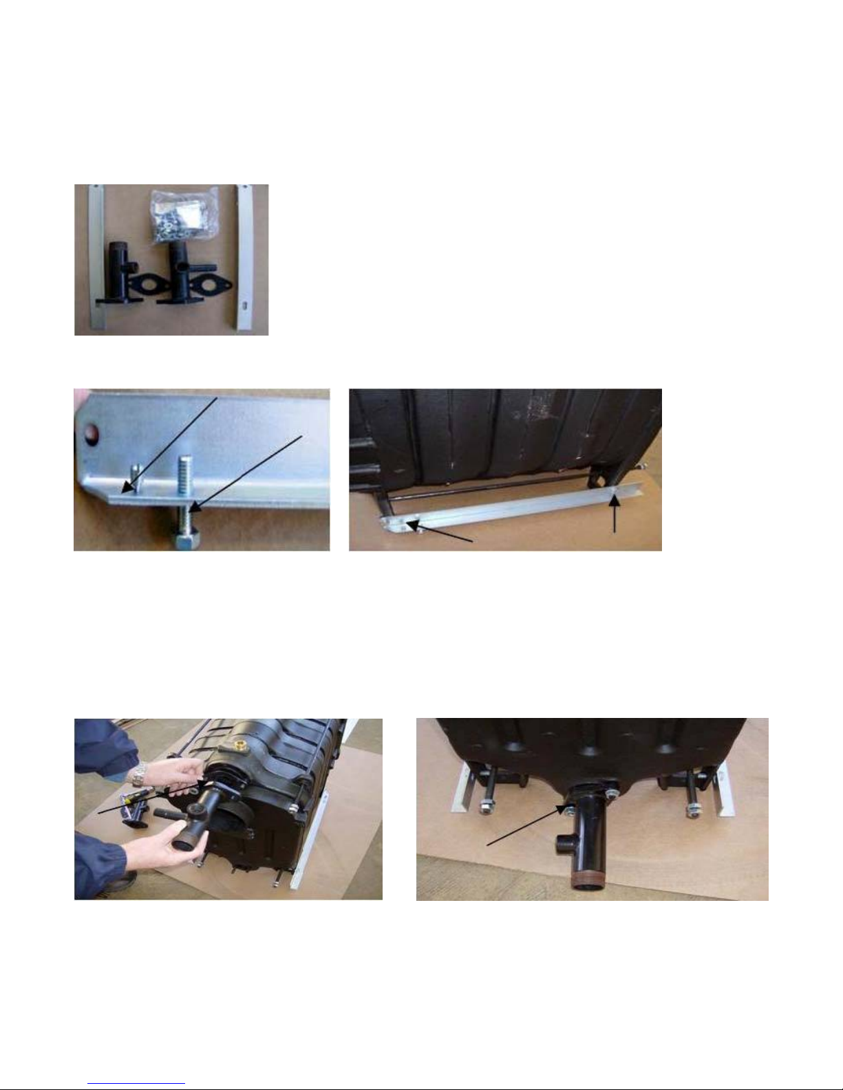
STEP 1 VERIFY CONTENTS OF JACKET ASSEMBLY PACKAGE.
Your jacket assembly will contain two (2) manifolds with gaskets, a
fastening package which includes all necessary bolts, screws, nuts
and washers for assembly along with burner studs, nuts and
washers, block insulation, rear of block insulation, aluminum faced
tape, leveling frame rails, two (2) side panels, a rear panel top
panel and re-insulated top and bottom front panels.
STEP 2 FRAME RAIL CONNECTION
Attach 10 mm bolts to the underside of the frame rails. These will be used to level the boiler.
Screw the 4 mm jacket affixing screw to the frame rail from the top down. Both the bolt and
affixing screw will be located on the same end of the frame rail. The frame rail will then be
bolted to the legs of the boiler with the frame rail and containing the affixing screw facing in the
direction of the front end of the boiler.
STEP 3 MANIFOLD INSTALLATION
Using the gaskets and bolts supplied connect the manifolds directly to the boiler block. The
top supply manifold will have a 3/4” npt tapping for a relief valve and 1/4” npt tapping for a
gauge. The bottom return manifold has 3/4” npt tapping for a drain vlave. Both manifolds
have 1-1/4” male npt threads for system connection.
5IM-OB-CAST-00 May/11
4
Page 6
GRANBY CAST IRON SERIES – INSTALLATION/OPERATION MANUAL
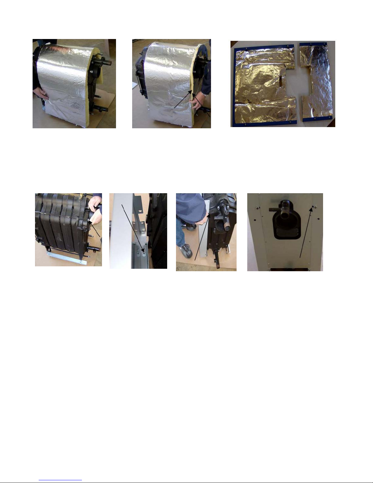
STEP 4 INSULATION INSTALLATION
Drape the large piece of block insulation directly over the block taking care to provide
adequate clearance from frame rails. Using the aluminum faced tape attach the preshaped
rear inslulation to the block insulation. The process is simply taping the two pieces together.
The front panels come pre-insulated.
STEP 5 SIDE AND BACK PANEL ATTACHMENT
Affix panel mounting nuts to the rear of the tie rods. Mount the side panels by placing the
panel over the frame rail so that the hole in the bottom lip of the panel fits directly over the
jacket affixing screw on the rail. You can then lock the panel in place by sliding it slightly
forward. The slot on the rear of the panel will now be in position to slide over the tie rod at the
rear of the boiler. Tighten the nuts on the tie rod end to firmly secure the panel. Repeat on the
other side. Screw the back panel to the side panels.
STEP 6 CONTROL SENSOR ATTACHMENT
Prior to jacket top and front panel installation the control sensor must be inserted into the brass
well located at the back of the boiler and secured by a clip. Feed the sensor through the hole
on the front of the right side panel from the outside. Penetrate the block insulation to insert the
sensor. The sensor must be fully inserted to the bottom of the well.
5IM-OB-CAST-00 May/11
5
Page 7

GRANBY CAST IRON SERIES – INSTALLATION/OPERATION MANUAL
STEP 7 TOP AND FRONT PANEL ATTACHMENT
Affix the top panel by placing the holes located on the underside of the panel over the jacket
affixing pins. Press down on the top panel and it will snap in place. Affix the lower front panel
by placing the openings on the lips of the panel over the jacket affixing screws and pushing
downward on the panel. The panel will lock in place. Repeat the process for the top front
panel.
Upon completion of the jacket assembly the control unit can be mounted on the side of the
boiler. The boiler is now ready for piping and connection to the fuel system, heating and
domestic hot water, thermostat and 110 Volt 60 cycle AC current.
CAUTION: Safety or relief valve discharge should be piped downward to within 6” of the floor
or to a drain. The valve must be mounted in a vertical position.
PIPING
Prior to connecting the BGC to an existing piping system certain procedures must be followed.
The system should be flushed to insure that scale and sludge will not be introduced to the
boiler. This is a must when replacing a gravity open system. The BGC is a low mass boiler
requiring low water content and steps must be taken to insure that the boiler is not flooded
from an existing high volume standing cast iron system. If the conversion is from a high
volume system a bypass loop must be installed. If high pressure testing of the existing system
is necessary make sure the BGC is isolated during the testing. Manual shut off valves must be
installed on both the supply line and on the boiler bypass loop. ASME Boiler Code requires
that feed or make up water be introduced to the piping system and not directly to the boiler.
Pressure reducing valves should be installed and adjusted to 12 psi cold water. The pressure
relief valve must be piped from the boiler and downward to within 6” of the floor or to a height
to meet existing code. An expansion tank, circulating pump and automatic air eliminators must
be part of the system. The relief valve, backflow preventer and drain valve should be piped
according to code to a drain with piping that is the same size as the relief valve.
All piping, including heating, domestic hot water and fuel lines must be done in accordance
with all local codes. It is suggested that you refer to the Water Installation Survey and
Hydronics Institute Residential Hydronic Heating Installation/Design Guide.
All piping must be properly sized, free from defect and be made of copper, steel, brass,
aluminum or PEX.
Test results have shown that the safest operating temperature range for modern boilers
including the BGC is 160°F to 200°F. Allowing the water temperature in the boiler to drop
below 160°F for an extended period of time can cause corrosion and boiler plugging.
5IM-OB-CAST-00 May/11
6
Page 8
GRANBY CAST IRON SERIES – INSTALLATION/OPERATION MANUAL
Circulation Pump
A calculation for proper pump selection must be performed for all installations. The pump(s)
should not be operated at maximum working pressures above 30 psi or maximum working
temperatures above 200°F and within limits advised by the manufacturer. The pump must not
be operated unless the system has been bled of all air and completely filled with water.
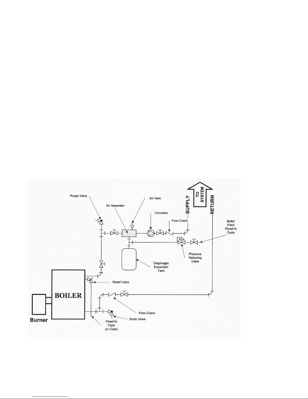
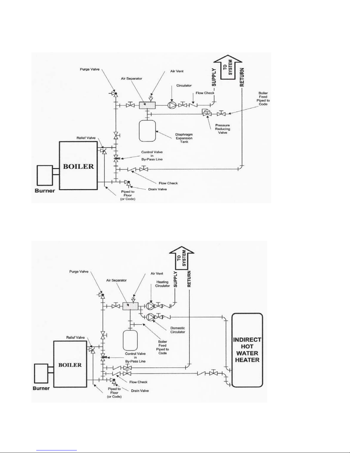
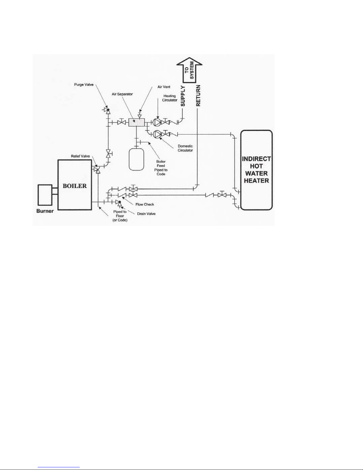
Recommended locations for the circulator, expansion tank, relief valve and other trim
are shown in Figure 1, Figure 2, Figure 3 and Figure 4.
Controls
The BGC Boiler package includes a aquastat. Based on your personal preference it will either
be a Honeywell L7248, a Hydrolevel Hydrostat Model 3250 or a Beckett Aquasmart model
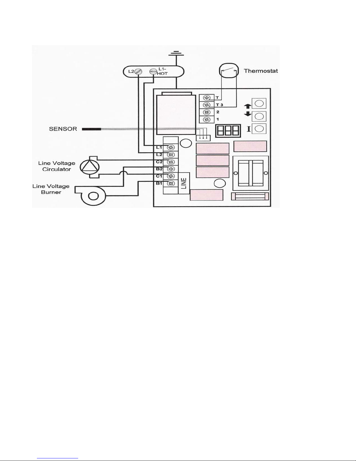
7600. Wiring diagrams for these controls are similar in the regard that the line Voltage is
applied to L1 and L2 and the burner connection is applied to B1 and B2. Please refer to the
Honeywell wiring diagram included in this manual on Figure 5 as well as diagrams for a priority
indirect application with a Taco SR503 or equivalent. For special control systems such as
outdoor reset, multiple zones, multiple boiler installations, unit heaters, radiant heating etc.
consult the respective manufacturers manual or contact Granby. For controls other than
Honeywell, please refer to the instructions supplied with these controls.
Figure 1
A typical installation with no domestic hot water and no by-pass loop installed.
5IM-OB-CAST-00 May/11
7
Page 9
GRANBY CAST IRON SERIES – INSTALLATION/OPERATION MANUAL
Figure 2
A typical installation with no domestic hot water and with a by-pass loop installed. The control
valve should be either a needle or throttling vlave.
Figure 3
A typical installation with domestic hot water supplied by an indirect heater and with a by-pass
loop installed. The control valve should be either a needle or throttling valve.
5IM-OB-CAST-00 May/11
8
Page 10
GRANBY CAST IRON SERIES – INSTALLATION/OPERATION MANUAL
Figure 4
A typical installation with domestic hot water supplied by an indirect heater and with no bypass loop installed.
WIRING
All external wiring must be performed in compliance with existing electrical codes within the
local jurisdiction. In the United States this is generally the NATIONAL ELECTRICAL CODE,
NFPA70. In Canada the CSA, STANDARD C22-1 and the Canadian Electrical Code.
Connections should be carried out in accordance with this manual and only by qualified
individuals.
• The boiler and burner should only be operated on 120 Vac.
• Field connections should be properly sized and protected with a minimum 15 amp fuse or
circuit breaker.
• A separate fused disconnect must be installed as required by code so that power can be
shut off for servicing.
• The boiler must be ground to the water piping or the main service ground.
• Room thermostats should be installed or relocated away from cold drafts, air currents,
lamps, televisions or sunlight. Set the heat anticipator on the thermostat to match the
operating control. Connect the thermostat leads to the circulation pump operating control
or aquastat as applicable.
The connections must be made in a manner to insure that there is no crossing of the neutral
with the phase, a proper ground is provided and all three wires are connected to the operating
control.
5IM-OB-CAST-00 May/11
9
Page 11
GRANBY CAST IRON SERIES – INSTALLATION/OPERATION MANUAL
Figure 5
Typical wiring for line voltage oil burner with Honeywell L7248 and one heating zone.
CAUTION: Oil fired units must always be connected to flues with proper daft.
VENTING REQUIREMENTS
All venting of the BGC Series Boilers shall be done in accordance with national, state and local
codes and be in conformity with NFPA 31 and CSA B139. In addition design of the chimney
connectors, chimneys, should also conform to State and local codes and be in accordance
with good and accepted industry practice. NFPA 211 should be used in lieu of local codes.
AN OIL-FIRED UNIT SHALL BE CONNECTED TO A VENT HAVING SUFFICIENT DRAFT AT ALL
TIMES TO ENSURE SAFE AND PROPER OPERATION OF THE UNIT.
Natural Draft Applications
Specific guidelines should be followed to prevent the occurrence of the following conditions:
• Condensation of flue gasses.
• Positive outlet draft conditions.
• Reverse flow of flue gas during or after burner shutdown.
Chimney Connection
To insure safe and efficient boiler operation flue gasses must be released through a clean,
properly sized chimney with adequate draft that meets all local codes and regulations and be
in accordance with NFPA 211 and NFPA 31 or CSA B139. Always inspect and clean the
chimney to insure that it is free from obstructions. The boiler must be connected to an
independent chimney flue and not with a shared flue pipe. Never connect the boiler to a
chimney or liner serving an open fireplace. Adjustable dampers in the chimney or flue pipe
should never be used.
5IM-OB-CAST-00 May/11
10
Page 12

GRANBY CAST IRON SERIES – INSTALLATION/OPERATION MANUAL
A 6” diameter flue pipe must be used for connection of the boiler flue outlet to the chimney for
the entire length of the connection. An exception can be made for the three, four and five
section boilers where the flue pipe may be reduced to 5” for the length of the connection. The
chimney connector should be at least 24 gauge metal, be properly supported and be free of as
many 90 degree turns as possible. The distance between the boiler and the chimney depends
on whether or not elbows are used. The distance should be at least 24” if no elbows are used
and 12” if elbows are used. The same holds true for the maximum length of the flue pipe. It
must be no longer than 10’ if no elbows are used and 6’ if elbows are used.
Condensation
The BGC Series boiler is a high efficiency boiler and as a result improper venting can lead to
condensing temperatures in the chimney connector and the venting system. If condensing
temperatures of below 250°F NET are reached in the chimney connector then additional steps
to insure proper draft must be taken. Make sure that all joints are properly sealed with a high
temperature silicone or mastic. If after sealing the joints the condition still exists then inspect
the chimney for suitability. If the masonry, brick, block chimney or tile chimney liner is in poor
condition a new chimney liner rated for oil may have to be installed. In the event the condition
still exists after installation of a new liner consult Granby.
Roof Clearances
Standard roof clearances apply. The installer is responsible for their adequacy.
DANGER: Never burn gasoline, waste oil or crankcase oil in this appliance.
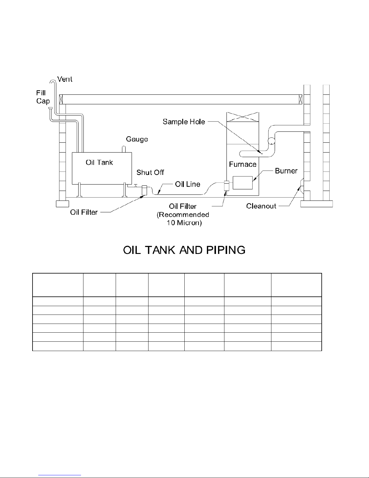
FUEL SYSTEM
The fuel system piping must comply with the pump manufacturers’ specifications which are
included with the burner. In addition all fuel system piping must comply with local codes and
ordinances.
• The quality of your fuel is of great importance. For most instances your burner is designed
to burn clean water free #2 fuel.
• The oil supply line should be constructed of seamless heavy wall copper tubing with flared
fittings. Only oil resistant pipe dope should be used on threaded connections. The use of
Telfon Tape will void manufacturers’ warranty. Lines must be airtight, clean and free of
kinks. All joints and threaded fittings must be checked for leaks. A vacuum gauge should
be employed when testing the installation. It is recommended that older fuel lines be
replaced.
• A two pipe system should only be used when the oil supply is well below the pump. A
return fuel line may be used on installations where the tank level is below the level of the
burner. The return line must be equal in diameter to the suction line. The minimum size
for the oil line is 3/8” copper tubing.
• A Tiger Loop is recommended when the oil supply line is located 5’ below the burner.
• Shut off valves must be installed in the supply line at or near the oil storage tank and at the
burner in compliance with all codes. Inspect the shut off valve spindle packing for
tightness to insure that there are no air leaks. The valve must always be shut off if the
burner is shut down for an extended period of time. The burner should be tagged to
indicate that the fuel supply has been closed off. The electrical circuit to the burner must
be cut off by removing the fuse or circuit breaker to insure that no operation of the burner
will occur while the fuel supply is shut off.
• Only fuel storage tanks bearing the Underwriters Laboratories label and accessories
approved as prescribed by local code may be used.
5IM-OB-CAST-00 May/11
11
Page 13
GRANBY CAST IRON SERIES – INSTALLATION/OPERATION MANUAL
• Never burn paper or garbage in the unit and check to insure that all rags, debris, stored
flammable liquids or products producing flammable vapors are removed from the area of
the boiler.
DO NOT USE GASOLINE, CRANKCASE DRAININGS OR ANY OIL CONTAINING GASOLINE.
GRANBY CAST IRON SERIES BURNER SPECIFICATIONS
Appliance
Model
GC2-3
GC2-4
GC2-5
GC2-6
GC2-7
GC2-8
No. of
Sections
3 18-7/8" 370 5.5 1-1/4" 1-1/4"
4 22-1/2" 437 6.9 1-1/4" 1-1/4"
5 26-3/4" 503 8.2 1-1/4" 1-1/4"
6 31-1/8" 569 9.5 1-1/4" 1-1/4"
7 35-1/2" 639 10.8 1-1/4" 1-1/4"
8 39-3/4" 705 12.2 1-1/4" 1-1/4"
Length
(inches)
Weight
(pounds)
5IM-OB-CAST-00 May/11
Water
Content
(us/gal)
12
Supply Outlet
(inches)
Return Outlet
(inches)
Page 14

GRANBY CAST IRON SERIES – INSTALLATION/OPERATION MANUAL
GRANBY CAST IRON SERIES / RIELLO & BECKETT SPECIFICATIONS
Item Burner Input Nozzle Pump Air Setting Turbulator Output Burner Insertion
Article Brûleur Entrée Gicleur Pompe Ajustement D’air Turbulateur Sortie Insertion du Brûleur
USGPH L/h (psi) Btu/h kW
B*C-E6-0085-** Riello F3 0.70 2.65 0.65 70B 120 3.40 0.0 85,000 25 3” 76 mm
B*C-N1-0085-** Beckett NX-LH-6 0.70 2.65 0.60 60W 140 1.50 N/A 85,000 25 2 3/4” 70 mm
B*C-E7-0122-** Riello F5 1.00 3.79 0.85 60B 140 2.25 0.0 122,000 36 3” 76 mm
B*C-N3-0122-** Beckett NX-LB-9 1.00 3.79 0.85 60B 140 3.75 N/A 122,000 36 2 3/4” 70 mm
B*C-E7-0152-** Riello F5 1.25 4.73 1.00 60W 160 2.75 1.0 152,000 45 3” 76 mm
B*C-N4-0152-** Beckett NX-LD-9 1.25 4.73 1.00 60W 160 0.50 N/A 152,000 45 2 3/4” 70 mm
B*C-E7-0174-** Riello F5 1.39 5.26 1.20 60B 135 3.75 1.0 174,000 51 3” 76 mm
B*C-E8-0194-** Riello F10 1.60 6.06 1.35 45B 145 2.50 1.0 194,000 57 3” 76 mm
B*C-E8-0224-** Riello F10 1.80 6.81 1.50 45B 145 2.75 2.0 224,000 66 3” 76 mm
WARNING: Do not operate if any controls have been submerged. Contact a qualified
technician for inspection prior to use.
START UP PROCEDURE
• Prior to start up make sure the service switch is in the OFF position.
• Check all fittings and wiring.
• Insure that the boiler and the entire heating system are completely filled with water and
that all air has been purged from the system resulting that proper system pressure is
achieved. The minimum PSIG is 12.
• Check to insure that clean quality #2 heating oil has been used to fill your storage tank.
• Open all manual shutoffs throughout the system.
• Set operating controls to the recommended settings.
• Follow the burner manufacturer’s instructions for proper light off and setting. Using
accurate combustion test equipment set the burner for proper “steady state” operation.
The use of accurate instruments is necessary to achieve maximum efficiency and lowest
fuel costs.
• Place this manual, the control manual and the burner manual along wit h related consumer
information in an easily accessible location. Installers should make the consumer aware
of the content and location of this information.
MAINTENANCE, SERVICE AND CONTROL TESTING
Your heating appliance is designed to be maintained and serviced only by your heating
professional. The following sections provide information on maintenance and service related
activities. In the event a problem occurs consult your heating professional.
CAUTION
ALWAYS KEEP THE OIL SUPPLY VALVE SHUT OFF IF THE BURNER IS SHUT DOWN
FOR AN EXTENDED PERIOD OF TIME. DO NOT START THE BURNER UNLESS ALL
CLEANOUT DOORS ARE SECURED IN PLACE. DO NOT TAMPER WITH THE UNIT OR
CONTROLS – CALL YOUR SERVICE PERSONNEL.
5IM-OB-CAST-00 May/11
13
Page 15

GRANBY CAST IRON SERIES – INSTALLATION/OPERATION MANUAL
HOMEOWNER SERVICE CAUTION
In the event of a problem with the heating system the homeowner should perform the following
limited activities.
• Check to make sure that there is fuel in the tank and that oil valves are open.
• Set the thermostat above existing room temperature.
• Check for blown fuses or circuit breakers and make sure power switches are in an on
position.
• NEVER TAMPER WITH CONTROLS, WIRING OR PIPING!!
CAUTION: Line voltage present care must be used when testing controls.
TESTING SAFETY AND CONTROL DEVICES
In the event the boiler is equipped with a low water cut off the cut off should be tested in
accordance with the manufacturer’s recommendations. When no instructions are available
follow the guidelines in ASME CSD-1 or perform the following procedures:
• Set room thermostat at least 10°F above room temperature.
• With Burner operating, drain boiler slowly until the burner shuts off. This shut off should
occur when the water level falls below the low water cut off probe.
• Check to be sure the burner shut off is not due to an open limit or flame safety issue.
• Reset the room thermostat to the desired temperature and refill the boiler.
CLEANING OF THE BOILER SECTIONS
Section cleaning should only be performed by a service technician and must only be
performed when the boiler is out of service. The following steps should be followed:
• Remove the front casing by sliding it upwards to release and then pull to remove.
• Open the front swing door by removing the four bolts; this will expose the chamber area as
well as the second and third passes.
• Remove the stainless steel ba ffles. With a cleaning brush clean the boiler section, second
and third passes.
• Remove the insulation and smokehood cleaning co ver from the rear section. Remove any
soot that may have collected in the smokehood. Replace insulation on the rear section.
• Replace swing door and tighten bolts.
• Refit the front casing.
FUEL SYSTEM AND BURNER CLEANING
Your burner manufacturer has supplied instructions for servicing and maintenance should be
performed as instructed. In addition the following fuel and related items should be serviced on
a regular basis:
• Service fuel filters and fuel unit.
• Service burner housing and fan.
• Replace nozzle using only the size and type recommended by the burner manufacturer.
• Service ignition system.
• Perform testing and check for proper operation of the primary control. Service primary
control.
PERFORM COMBUSTION TEST
The burner must be adjusted to insure proper CO2 and O2 levels with no more than True Zero
Smoke. Continue adjustments until the proper level is achieved.
5IM-OB-CAST-00 May/11
14
Page 16
GRANBY CAST IRON SERIES – INSTALLATION/OPERATION MANUAL
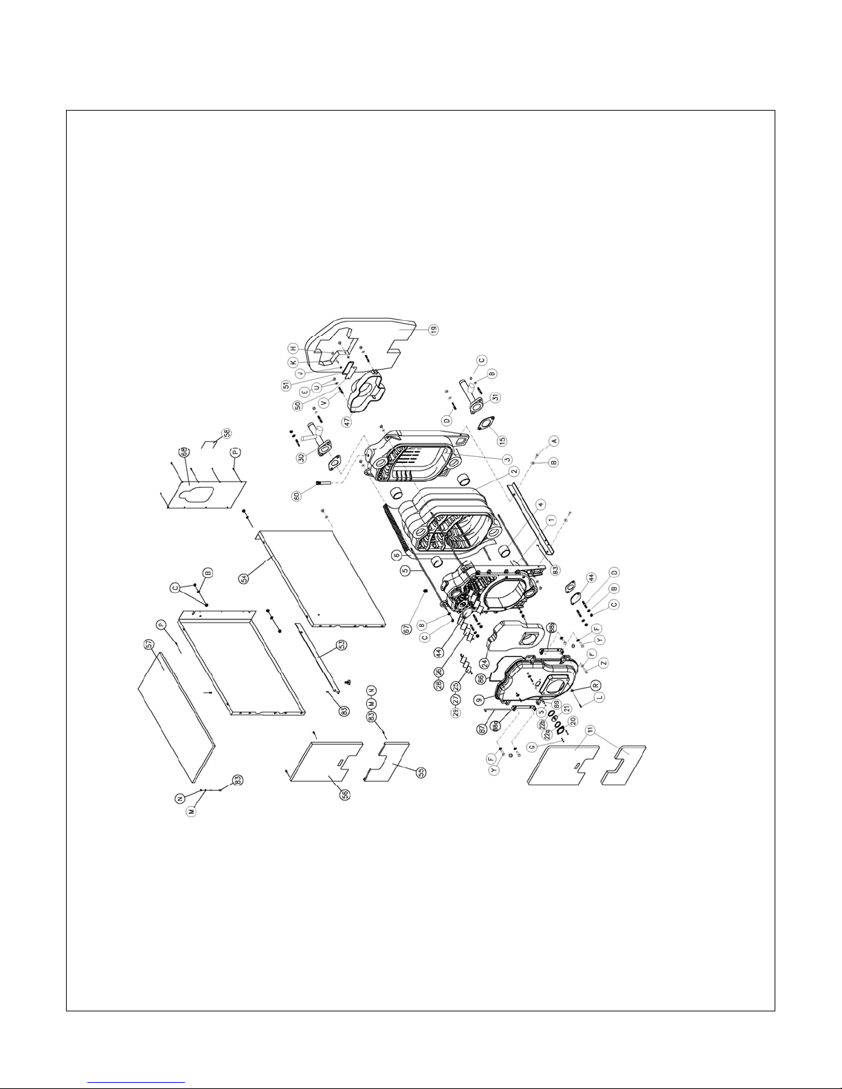
BOILER DIAGRAM AND PARTS LIST
See the parts list on the next page
5IM-OB-CAST-00 May/11
15
Page 17

GRANBY CAST IRON SERIES – INSTALLATION/OPERATION MANUAL
Number PART NAME Number PART NAME
1 GC2 FRONT SECTION 60 GC PNA - POCKET FOR SENSING BULBS
2 GC2 INTERMEDIATE SECTION 67 TAPPING WITH AIR RELIEF VALVE
3 GC2 REAR SECTION 68 REAR CASING
4 NIPPLE 83 SPECIAL PIN FOR CASING ASSEMBLY
5 STAYBOLTS 86 FIBRE-GLASS ROPE DIA. 10
6 BODY INSULATION 87 HINGE PIN
9 FRONT DOOR (MONOBLOCK) 88a HINGE - LEFT HAND SIDE
11 FRONT INSULATION 88b HINGE - RIGHT HAND SIDE
15 RUBBER GASKET 89 OUTLET FOR PRESSURE MEASUREMENT
19 REAR INSULATION A SETSCREW M10 x 30
20 SIGHTGLASS FRAME B WASHER A10.5
21 SIGHTGLASS C NUT M10
22a SIGHTGLASS FRAME INSULATION D STUD M10 x 40
22b SIGHTGLASS INSULATION E NUT M8
24 FRONT DOOR REFRACTORY F WASHER A8.4
25 / 27 / 29 2ND PASS RETARDERS G SETSCREW M5 x 15
26 / 28 3RD PASS RETARDERS H NUT M6
30 DELIVERY STUB PIPE J WASHER A6.4
31 RETURN STUB PIPE K STUD M6 x 22
44 BLANK FLANGE L SELF TAPPING SCREW S6.3 x 30
47 SMOKEHOOD DIA.150 MM M SERRAT ED WASHER A4.3
50 SMOKEHOOD CLEANING COVER INSULATION N NUT M4
51 SMOKEHOOD CLEANING COVER P SELF TAPPING SCREW S4.8 x 9.5
53 CHASSIS - LEFT/RIGHT HAND SIDE R WASHER A6.4
54 SIDE CASINGS - LEFT/RIGHT HAND SIDE S SETSCREW M3 x 6
55 FRONT CASING LOWER PART U WASHER A9
56 FRONT CASING UPPER PART V STUD M8 x 50
57 ÜST SAC Y SETSCREW M8 x 16
58 BOILER DATA PLATE Z SETSCREW M8 x 30
5IM-OB-CAST-00 May/11
16
 Loading...