

Page 1
Installation, Operation and
Service Manual
Cast Iron Boiler SERIES
B*G, 3 sections illustration
INSTALLATIONS MUST MEET ALL LOCAL AND FEDERAL
CODES THAT MAY DIFFER FROM THIS MANUAL
THE FOLLOWING PAGES INCLUDES WARNINGS, INSTALLATION AND MAINTENANCE
INSTRUCTIONS SPECIFIC TO GAS-FIRED UNITS. PLEASE REVIEW THIS MANUAL
CAREFULLY IF YOUR BOILER IS NATURAL GAS-FIRED OR PROPANE GAS-FIRED
Please read the manual in its entirety before beginning installation.
This manual must be kept with the boiler for future reference.
GRANBY FURNACES INC.
PO Box 637
12118 Hwy 209
Parrsboro Nova Scotia Canada
B0M 1S0
www.granbyindustries.com 04-07-2015 G2014-E5G Rev. D
Gas
-
Fire
B*G-3 sections
B*G-4 sections
B*G-5 sections
B*G-6 sections
B*G-7 sections
B*G-8 sections
* = Brand name, G=Gas
Page 2

1
N
OTE:
THE BURNER INSTRUCTION MANUAL AND THE BURNER USER’S
INFORMATION MANUAL ARE CONSIDERED PART OF THIS MANUAL
AND THEIR INSTRUCTIONS MUST BE FOLLOWED EXCEPT WHEN
SPECIFICALLY MENTIONNED IN THIS MANUAL.
WARNING: If the information in this manual is not followed
exactly, a fire or explosion may result, causing property damage,
personal injury or death.
- Do not store or use gasoline or other flammable vapors or
liquid in the vicinity of this or any other appliance.
- WHAT TO DO IF YOU SMELL GAS
o Do not try to light the appliance,
o Do not touch any electrical switch; do not use any
phone in your building,
o Immediately call your gas supplier from an outside
p
hone. Follow the gas supplier’s instructions,
o If you cannot reach your gas supplier,
call the fire department.
- Installation and service must be performed
by
a qualified installer, service agency or the
gas supplier.
Page 3

2
TABLE OF CONTENTS
B
*C - Gas
1.0 IMPORTANT SAFETY ADVICE 3
2.0 PRODUCT INFORMATION 4
3.0 UNIT INSTALLATION 5
3.1 PLACEMENT & LEVELING OF THE UNIT 5
3.2 JACKET ASSEMBLY & CONTROL INSTALLATION 5
4.0 PIPING 9
5.0 ELECTRIC WIRING 12
6.0 CHIMNEY INFORMATION 14
7.0 FUEL SYSTEM 17
7.1GAS-FIRED BOILERS 17
8.0 ACCESSORY INSTALLATION 21
9.0 BURNER INSTALLATION & SETTING 22
9.1 GAS-FIRED BOILERS 23
9.2 GAS-FIRED BOILERS LIGHTING INSTRUCTIONS 25
10.0 TECHNICAL INFORMATION 26
10.1 GAS-FIRED BOILERS 26
10.2 BOILER INFO 28
11.0 BOILER START UP & OPERATION 28
11.1 START UP PROCEDURE 28
11.2 L7248 HONEYWELL CONTROL 29
11.3 TROUBLE SHOOTING THE CONTROL 30
12.0 MAINTENANCE / SERVICE 31
12.1 CLEANING THE BOILER 32
12.2 BURNER CLEANING NOTES 33
12.3 PERFORM COMBUSTION TEST 33
13.0 EXPLODED PARTS VIEW 34
Page 4

3
1.0 IMPORTANT SAFETY ADVICE
Please read and understand this manual before installing, operating or
s
ervicing the furnace. To ensure you have a clear understanding of the
operating procedures of the appliance please take the time to read section
IMPORTANT SAFETY ADVICE of this manual.
THE INSTALLATION OF YOUR GAS-FIRED BOILER MUST CONFORM TO THE
REQUIREMENT OF THE AUTHORITY HAVING JURISDICTION OR IN THE ABSENCE OF
SUCH REQUIREMENTS, TO THE NATIONAL FUEL GAS CODE ANDSI Z223.1/NFPA 54
AND/OR NATIONAL GAS AND PROPANE INSTALLATION CODE CAN/CSA B149.1.
WHERE REQUIRED BY THE AUTHORITY HAVING JURISDICTION, THE INSTALLATION
MUST CONFORM TO THE STANDARD FOR CONTROLS AND SAFETY DEVICES FOR
AUTOMATICALLY FIRED BOILERS ANSI/ASME CSD1.
SHOULD OVERHEATING OCCUR OF THE GAS SUPPLY FAILS TO SHUT DOWN, DO
N
OT TURN OFF OR DISCONNECT THE POWER SUPPLY TO THE CIRCULATOR,
INSTEAD SHUT OFF THE GAS SUPPLY AT A LOCATION EXTERNAL TO THE
APPLIANCE.
DO NOT USE THIS BOILER IF ANY PART HAS BEEN UNDER WATER. IMMEDIATELY
CALL A QUALIFIED SERVICE TECHNICIAN TO INSPECT THE BOILER AND TO
REPLACE ANY PART OF THE CONTROL SYSTEM AND ANY GAS CONTROL, WHICH
HAS BEEN UNDER WATER.
CAUTION
DO
NOT START THE BURNER UNTIL ALL FITTINGS, COVERS AND DOORS ARE IN
PLACE. DO NOT TAMPER WITH THE BOILER OR CONTROLS, CALL A QUALIFIED
BURNER TECHNICIAN. DO NOT STORE OR USE GASOLINE OR OTHER FLAMMABLE
VAPOURS AND LIQUIDS IN THE VICINITY OF THIS UNIT OR ANY OTHER APPLIANCE.
IMPORTANT
This manual contains instructional and operational information for the B*G GAS-FIRED boiler .
Read the instructions thoroughly before installing boiler or starting the burner. Consult local
authorities about your local FIRE SAFETY REGULATIONS. All installations must be in
accordance with local state or provincial codes. Improper installation will result in voiding of
warranty.
Page 5
4
2.0 PRODUCT INFORMATION
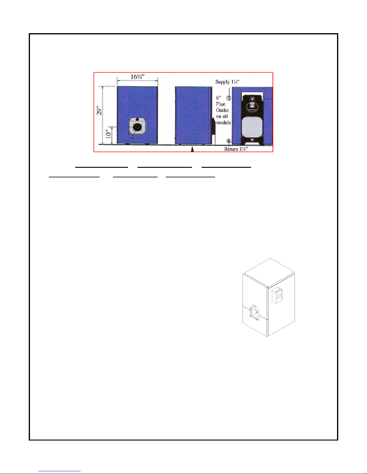
PHYSICAL DIMENSIONS
Length : ( 3 sections 18 7/8 ‘’ ) ( 4 sections 22 1/2’’ ) ( 5 sections 26 ¼’’ )
( 6 sections 31 1/8’’ ) ( 7 sections 35 ½’’) ( 8 sections 39 ¼’’)
CLEARANCE
Proper clearances must be maintained not only from combustible materials but also to provide
adequate access for servicing. All installations must comply with local codes and CSA B149.1
(gas) in Canada and NFPA 54 (gas) in the United States. Consult local fire codes for required
clearances. Connections to chimney must be made with the proper gauge thickness and
diameter of fluepipe as required by CSAB149.1,NFPA 54, whichever is applicable.
CLEARANCE (minimum) FOR SERVICING – Gas
Front 24” (609 mm)
Rear 24” (609 mm)
Left Side 24” (609 mm)
Right Side 2” (50.8 mm)
Top 10” (254 mm)
CLEARANCE (minimum) TO COMBUSTIBLES – Gas
Top 10” (254 mm)
Front 24” (609 mm)
Rear 24” (609 mm)
Left Side 24” (609 mm)
Right Side 2” (50.8 mm)
Chimney Connector 9” (229 mm)
SPECIFIC TO GASFIRED BOILERS
*** A gasfired boiler must NOT be installed on carpeting.
D
RAFT PRESSURE
Breech draft pressure -0.02’’ w.c. – Gas-Fired Boiler
Page 6

5
FLUE PIPE CONNECTION
GasFired boilers (C
HIMNEY ONLY applications)
CLEANOUTS
Rear removable smoke hood cover & Combustion Front Door Opening
FUEL
GasFired Natural Gas or Liquefied Petroleum Gas LPG
ELECTRICAL
CANADA : 120 Volts, 60Hz,15 amps fuse or breaker
U
SA : 13.3 amps, circuit protection 20 amps.
AIR SUPPLY
CAUTION: Adequate air supply for both combustion and ventilation must be available.
See page 17 for details.
3.0 Unit installation
3.1 PLACEMENT & LEVELING OF THE UNIT
The boiler should be located on firm foundation in an easily accessible area that meets the
previously discussed clearances and air requirements. In situations where the floor may be
uneven the unit may be levelled by using the leg levellers provided on the boiler or through the
insertion of shims under the legs.
3.2 JACKET ASSEMBLY AND CONTROL INSTALLATION
The boiler jacket has been designed for ease of assembly and removal. The following step-bys
tep process will ease installation. A screwdriver, 17 mm socket and ratchet or a 17 mm
wrench or adjustable wrench are needed.
Adjustable
Leg Leveler
Rail
Page 7
6
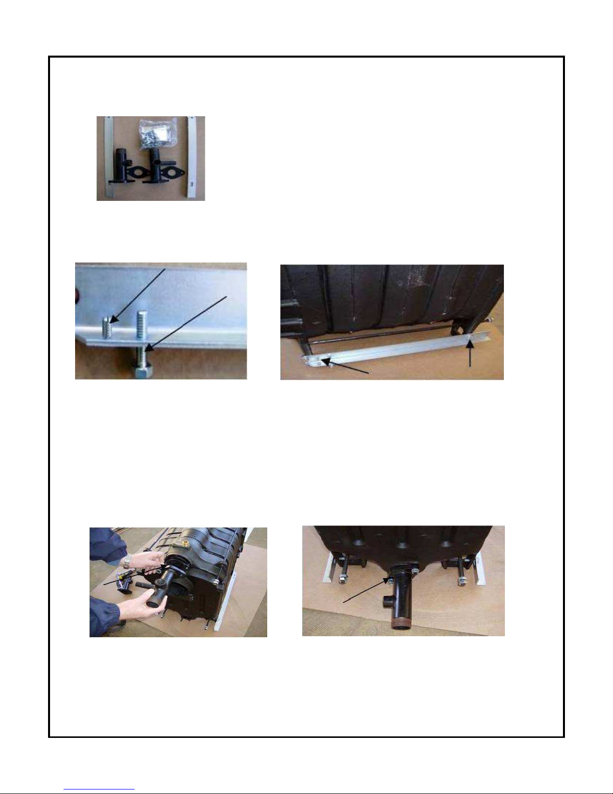
STEP 1 VERIFY CONTENTS OF JACKET ASSEMBLY PACKAGE.
Your jacket assembly will contain two (2) manifolds with gaskets, a
fastening package which includes all necessary bolts, screws, nuts
and washers for assembly along with burner studs, nuts and
washers, block insulation, rear of block insulation, aluminum faced
tape, levelling frame rails, two (2) side panels, a rear panel top
panel and re-insulated top and bottom front panels
S
TEP 2 FRAME RAIL CONNECTION
Attach 10 mm bolts to the underside of the frame rails. These will be used to level the boiler.
Screw the 4 mm jacket affixing screw to the frame rail from the top down. Both the bolt and
affixing screw will be located on the same end of the frame rail. The frame rail will then be
bolted to the legs of the boiler with the frame rail and containing the affixing screw facing in the
direction of the front end of the boiler.
S
TEP 3 MANIFOLD INSTALLATION
Using the gaskets and bolts supplied connect the manifolds directly to the boiler block. The
top supply manifold will have a 3/4” npt tapping for a relief valve and 1/4” npt tapping for a
gauge. The bottom return manifold has 3/4” npt tapping for a drain vlave. Both manifolds have
1-1/4” male npt threads for sytem connection.
Page 8
7
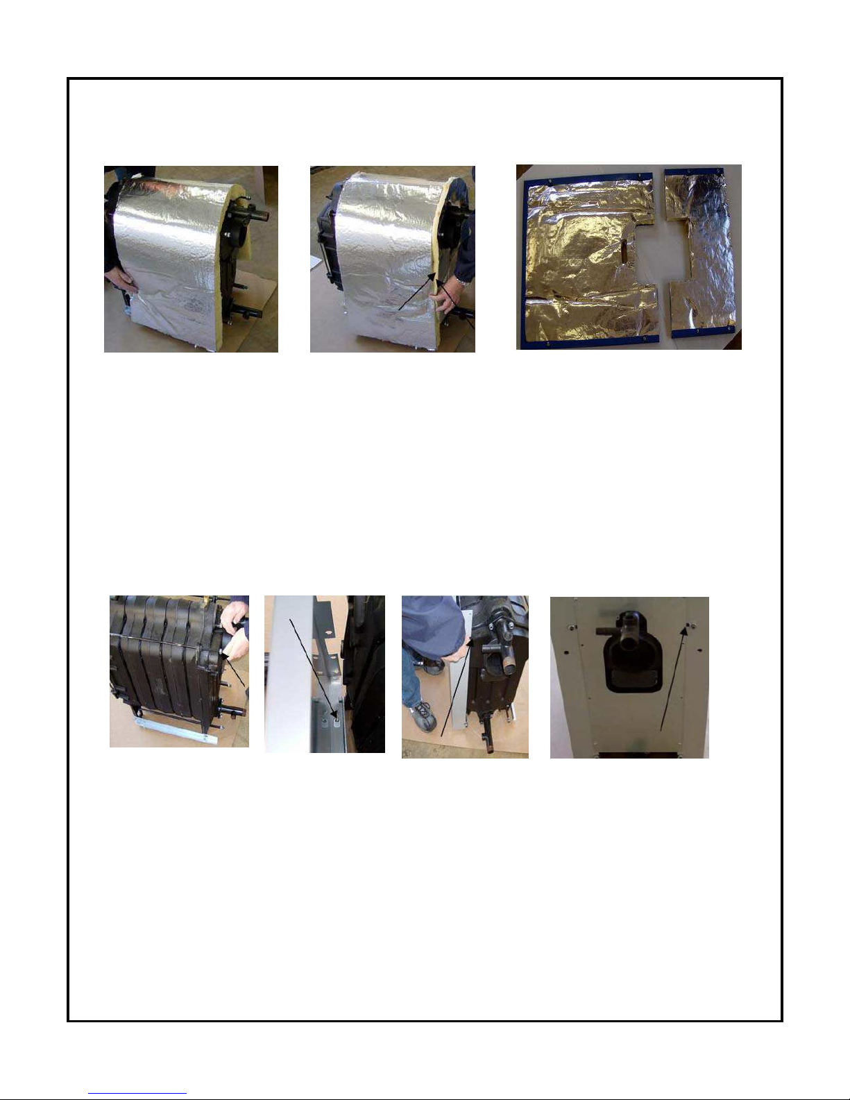
STEP 4 INSULATION INSTALLATION
Drape the large piece of block insulation directly over the block taking care to provide adequate
c
learance from frame rails. Using the aluminum faced tape attach the preshaped rear
inslulation to the block insulation. The process is simply taping the two pieces together. The
front panels come pre-insulated.
STEP 5 SIDE AND BACK PANEL ATTACHMENT
Affix panel mounting nuts to the rear of the tie rods. Mount the side panels by placing the
p
anel over the frame rail so that the hole in the bottom lip of the panel fits directly over the
jacket affixing screw on the rail. You can then lock the panel in place by sliding it slightly
forward. The slot on the rear of the panel will now be in position to slide over the tie rod at the
rear of the boiler. Tighten the nuts on the tie rod end to firmly secure the panel. Repeat on the
other side. Screw the back panel to the side panels.
¸
Page 9
8
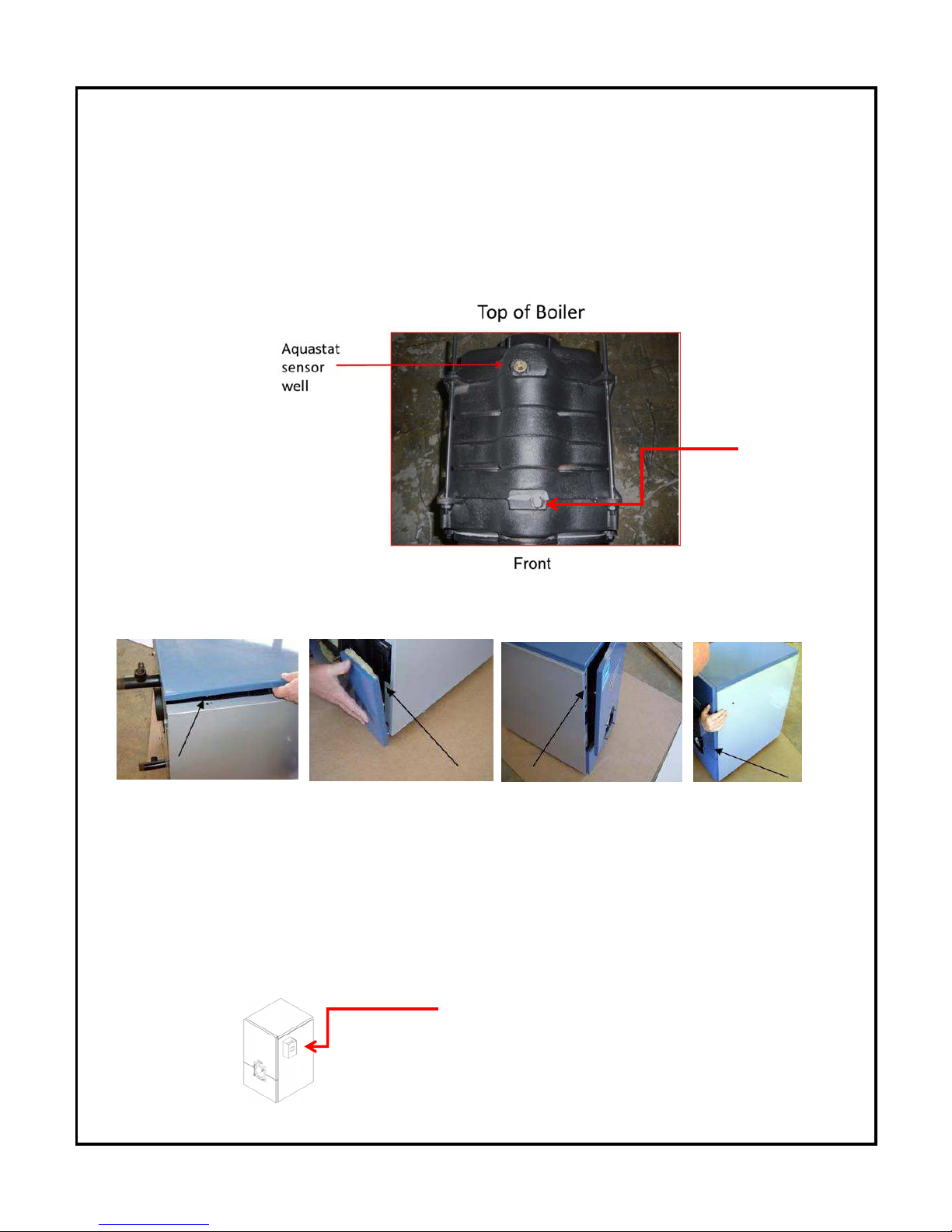
STEP 6 CONTROL SENSOR ATTACHMENT
Prior to jacket top and front panel installation the control sensor must be inserted into the brass
well located on the top of the boiler and secured by a clip. Feed the sensor through the hole
on the front of the right side panel from the outside. Penetrate the block insulation to insert the
sensor. The sensor must be fully inserted to the bottom of the well.
STEP 7 TOP AND FRONT PANEL ATTACHMENT
Affix the top panel by placing the holes located on the underside of the panel over the jacket
a
ffixing pins. Press down on the top panel and it will snap in place. Affix the lower front panel
by placing the openings on the lips of the panel over the jacket affixing screws and pushing
downward on the panel. The panel will lock in place. Repeat the process for the top front
panel.
Upon completion of the jacket assembly the Honeywell control can be mounted on the
side of the boiler. (Left or right)
Boiler control
Manual
Air Vent
Page 10

9
T
he boiler is now ready for piping and connection to the fuel system, heating and
domestic hot water, thermostat and 110 Volt - 60Hz power source.
CAUTION: Safety or relief valve discharge should be piped downward to within
6” of the floor or to a drain. The valve must be mounted in a vertical position.
4.0 PIPING
Prior to connecting the B*C/G boiler to an existing piping system, certain procedures must be
f
ollowed. The system should be flushed to insure that scale and sludge will not be introduced
to the boiler. This is a must when replacing a gravity open system.
The boiler is a low mass boiler requiring low water content and steps must be taken to insure
that the boiler is not flooded from an existing high volume standing cast iron system. If the
conversion is from a high volume system a bypass loop must be installed.
Manual shut off valves must be installed on both the supply line and on the boiler bypass
loop. ASME Boiler Code requires that feed or make up water be introduced to the piping
system and not directly to the boiler. Pressure reducing valves should be installed and
adjusted to 12psi cold water. The pressure relief valve must be piped from the boiler and
downward to within 6” of the floor or to a height to meet existing code. An expansion tank,
circulating pump and automatic air eliminators must be part of the system. The relief valve,
backflow preventer and drain valve should be piped according to code to a drain with piping
that is the same size as the relief valve. The installation of the relief valve must be consistent
with ANSI/ASME Boiler and pressure vessel code Section IV or Boiler, Pressure vessel and
Pressure piping code CSA B51 as applicable.
All piping, including heating, domestic hot water and fuel lines must be done in accordance
with all local codes. It is suggested that you refer to the Water Installation Survey and
Hydronics Institute Residential Hydronic Heating Installation/Design Guide. All piping must be
properly sized, free from defect and be made of copper, steel, brass, aluminum or PEX.
Circulating Pump
A calculation for proper pump selection must be performed for all installations. The pump(s)
s
hould not be operated at maximum working pressures above 30 psi or maximum working
temperatures above 185°F and within limits advised by the manufacturer. The pump must not
be operated unless the system has been bled of all air and completely filled with water.
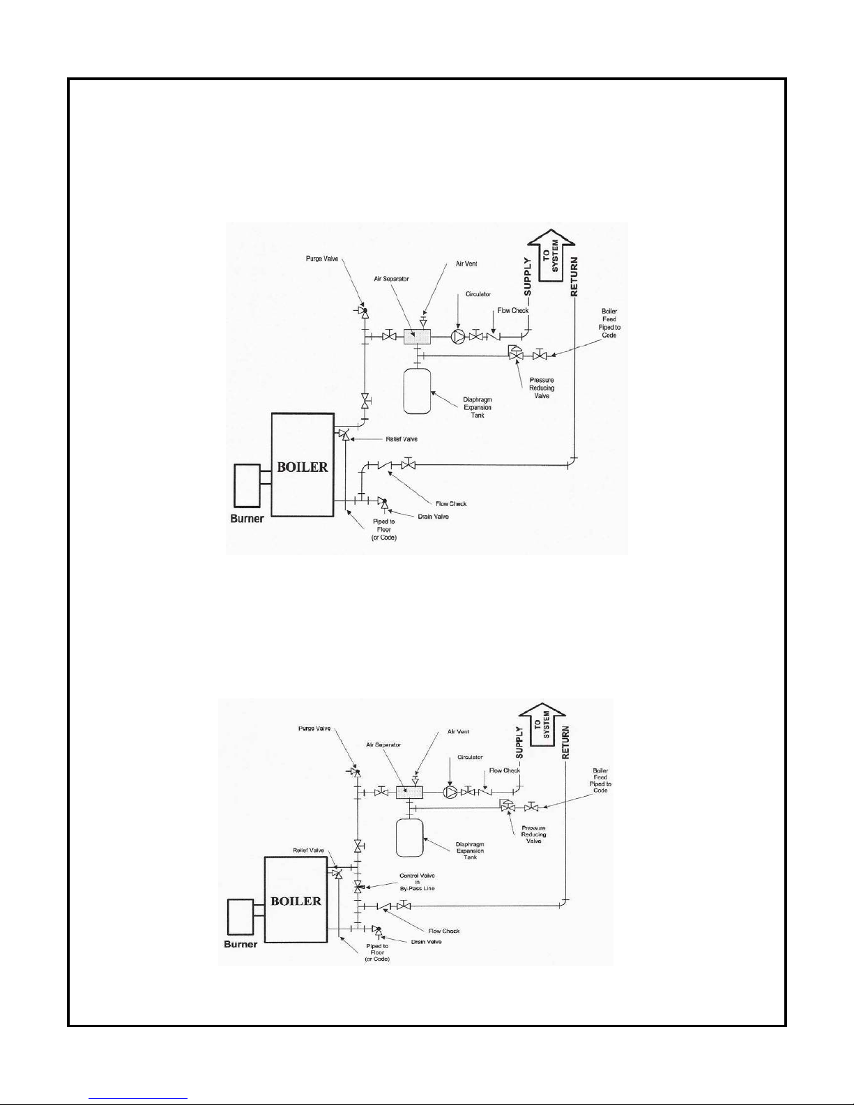
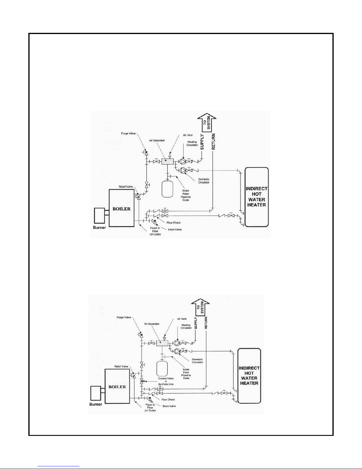
Recommended locations for the circulating pump, expansion tank, relief
valve and other trim are shown in Figure 1, Figure 2, Figure 3 and Figure 4.
Page 11
10
F
igure 1
A typical installation with no domestic hot water and no by-pass loop
installed.
Figure 2
A
typical installation with no domestic hot water and with a by-pass loop
installed.
Page 12
11
F
igure 3
A typical installation with domestic hot water supplied by an indirect heater
and with no by-pass loop installed.
Figure 4
A typical installation with domestic hot water supplied by an indirect heater
a
nd with a by-pass loop installed.
Page 13

12
P
IPING INSTRUCTIONS SPECIFIC TO GASFIRED BOILERS
• A hot water boiler installed above radiation level or as required by the authority
having jurisdiction, must be provided with a low water cut off device either as part
of the boiler or at the time of boiler installation.
• The boiler shall be installed in such a way that the gas ignition system components
are protected from water (dripping, spraying, etc.) during appliance operation and
service (circulator replacement, condensate trap, control replacement, etc.).
• The boiler, when used in conjunction with a refrigeration system, must be installed
so the chilled medium is piped in parallel with the boiler with appropriate valves to
prevent the chilled medium from entering the boiler.
• The boiler piping system of a hot water boiler connected to the heating coils
located in air handling units where they may be exposed to refrigerated air
circulation must be equipped with flow control valves or other automatic means to
prevent gravity circulation of the boiler water during the cooling cycle.
5.0 ELECTRICAL WIRING
All external wiring must be performed in compliance with existing electrical codes within the
l
ocal jurisdiction. In Canada the CSA, STANDARD C22-1 and the Canadian Electrical Code.
Only qualified individuals should carry out electrical connections in accordance with this
manual and;
• The boiler and burner should only be operated on 120 Vac – 60Hz.
• Field connections should be properly sized and protected with a minimum 15-amp fuse or
circuit breaker.
• A separate fused disconnect must be installed as required by code so that power can be
shut off for servicing.
• The boiler must be bounded to the water piping or the main service ground.
• If an external electrical source is utilized, the boiler, when installed, must be
electrically bounded to ground in accordance with the requirement of the
authority having jurisdiction, or in the absence of such requirement, with the
Page 14
13
National electrical code ANSI/NFPA 70 and/or the Canadian electrical code Part 1,
C
SA 22.1, electrical code as applicable.
• Label all wires prior to disconnection when servicing controls. Wiring errors can
cause improper and dangerous operation.
The connections must be made in a manner to insure that there is no crossing of the neutral
with the phase, a proper ground shall be provided and all three wires shall be connected to
the operating control.
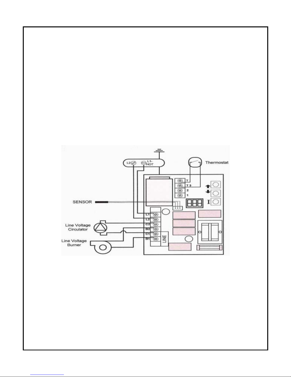
T
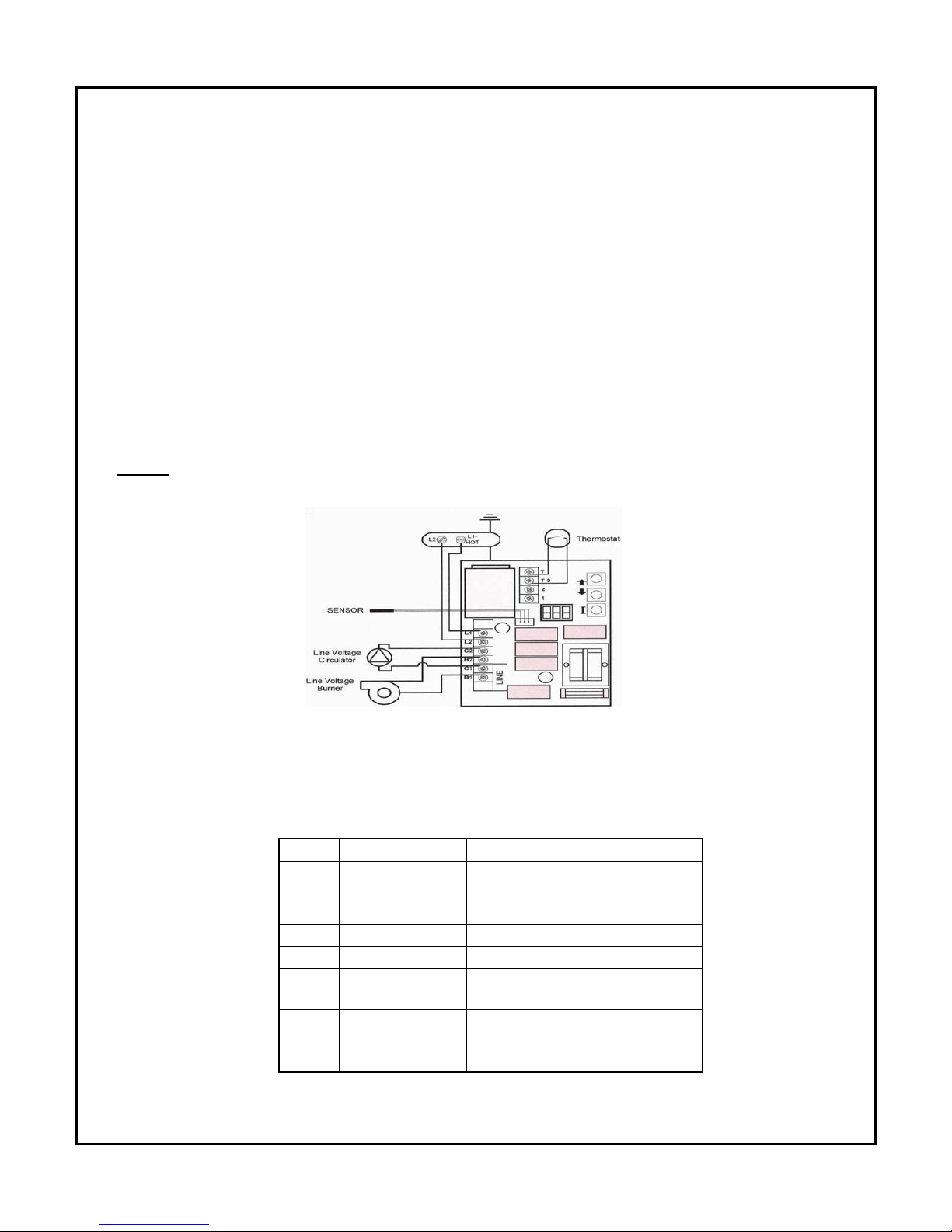
ypical line voltage wiring for oil or gas burner with Honeywell L7248 boiler
control and one heating zone.
Note:
•
For Canadian application, see page 21 for proper wiring with a Block Vent Shut-Off
- BVSO safety device.
• With the Carlin EZ Gas burner, the Red/White lead on the burner relay must
be connected with L1 on the boiler control, the black lead to B1 and the
white lead to B2 on the boiler control.
• With the Riello Gas burner, B1 must be connected to L on the burner
c
ontrol and B2 with N on the burner control.
Page 15
14
6
.0 CHIMNEY INFORMATION
Natural Draft Applications
CAUTION: Gas fired units must always be connected to flues with proper draft.
Specific guidelines should be followed to prevent the occurrence of the following conditions:
• Reverse flow of flue gas during or after burner shutdown.
• Positive outlet draft conditions.
• Condensation of flue gasses
Chimney Connection
To insure safe and efficient boiler operation flue gasses must be released through a clean,
p
roperly sized chimney with adequate draft that meets all local codes and regulations and be in
accordance with CSA B149.1 or NFPA 54 whichever applicable. Always inspect and clean the
chimney to insure that it is free from obstructions. Never connect the boiler to a chimney or
liner serving an open fireplace.
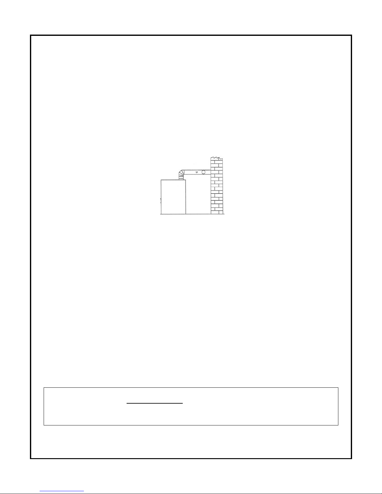
A 6” diameter flue pipe must be used for connection of the boiler flue outlet to the
chimney for the entire length of the connection. An exception can be made for the three,
four and five section boilers where the flue pipe may be reduced to 5” for the length of the
connection. The chimney connector should be at least 24 gauge metal, be properly supported
and be free of as many 90 degree turns as possible. The distance between the boiler and the
chimney depends on whether or not elbows are used. The distance should be at least 24” if no
elbows are used and 12” if elbows are used. The maximum length of the flue pipe. It must be
no longer than 10’ if no elbows are used and 6’ if elbows are used.
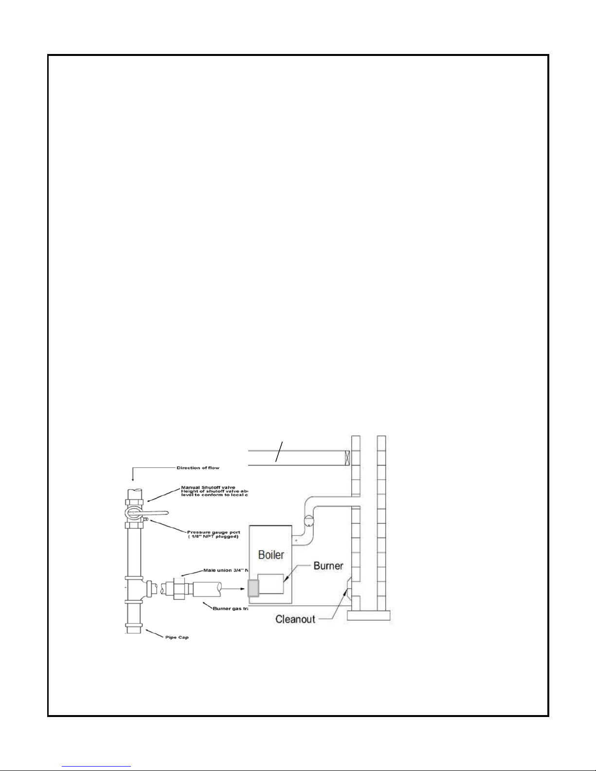
Draft Regulator
GasFired units: A double acting draft regulator must be installed on
the flue pipe.
Page 16

15
C
ondensation
The B*G Series boiler is a high efficiency boiler and as a result improper venting can lead to
condensing temperatures in the chimney connector and the venting system. If condensing
temperatures of below 250°F NET are reached in the chimney connector then additional steps
shall be taken to insure proper draft. Make sure that all joints are properly sealed with a high
temperature silicone or mastic. If after sealing the joints the condition still exists then inspect
the chimney for suitability. If the masonry, brick, block chimney or tile chimney liner is in poor
condition, a new chimney liner rated for oil may have to be installed. In the event the condition
still exists after installation of a new liner consult Granby Furnaces Inc.
SPECIFIC TO GASFIRED BOILERS
When an existing boiler is removed from a common venting system, the common
venting system is likely to be too large for proper venting of the appliances connected
to it. At the time of removal of the existing boiler, the following steps shall be
followed with EACH appliance remaining connected to the common venting system,
while the other appliances remaining connected to the common venting system are
not in operation:
1. Seal any unused openings in the venting system.
2. Visually inspect the venting system for proper size and horizontal pitch and
determine there is no blockage or restriction, leakage, corrosion and other
deficiencies which could cause an unsafe operation.
3. Insofar as is practical, close all building doors and windows and all doors
between the space in which the appliances remaining connected to the common
venting system are located and other spaces of the building. Turn on clothes
dryer and any appliance not connected to the common venting system. Turn on
any exhaust fans, such as range hoods and bathroom exhausts, so they will
operate at maximum speed. Do not operate a summer exhaust fan. Close
fireplace dampers.
Page 17

16
4. P
lace in operation the appliance being inspected. Follow the lighting
instructions. Adjust thermostat operation so appliance will operate
continuously.
5. Test for spillage at the draft regulator outlet / draft hood opening after 5
minutes of main burner operation. Use the flame of a match or candle, or
smoke from a cigarette, cigar, or pipe.
6. After it has been determined that each appliance remaining connected to the
common venting system properly vents when tested as outlined above, return
doors, windows exhaust fans, fireplace dampers and any other gasburning
appliance to their previous condition of use.
7. Any improper operation of the common venting system should be corrected so
the installation conforms with the National fuel gas code ANSI Z223.1/NFPA 54
and/or the Natural gas and propane installation code CAN/CSA B149.1. When
resizing any portion of the common venting system, the common venting
system should be resized to approach the minimum size as determined by the
appropriate tables in chapter 13 of the National fuel gas code ANSI
Z223.1/NFPA 54 and/or the Natural gas and propane installation code
CAN/CSA B149.1.
For boilers connected to gas vent or chimneys, vent installation must be in
accordance with the “Venting of equipment” section of the National fuel gas code
ANSI Z223.1/NFPA 54 or the “Venting systems and air supply for appliances” section
of the Natural gas and propane installation code CAN/CSA B149.1, or applicable
provisions of the local building codes.
Vent connectors serving appliances vented by natural draft shall not be connected
into any portion of mechanical draft system operating under positive pressure.
Page 18
17
Use of cellular core PVC (ASTM F*891), cellular core CPVC or Radel
(
Polyphenolsulfone) in venting systems shall be prohibited.
Connecting nonmetallic vent pipe and fittings with thermal insulation shall be
prohibited.
Horizontal portions of the venting system shall be supported to prevent sagging by
installing support every 36 inches. The horizontal runs must be sloping upwards not
less than ¼ inch per foot from the boiler to the chimney connector.
7.0 FUEL SYSTEM
(COMBUSTION & VENTILATION OPENINGS)
Install openings and ductwork to the boiler room providing fresh out-side combustion
a
nd circulating air, as installation code require by Canada CSA B139 or NFPA 31
whichever applicable. If installed in a closed room, provide two free air ventilation
openings of at least 8’’ x 12’’ (96 sq in.) free flow areas near celling and floor. Oil
burners must have sufficient air to allow vent system to operate properly.
Draft
regulator
Page 19

18
7.1 GasFired boilers
T
he gas piping must be installed between the gas meter and the combination gas
valve on the boiler.
WARNING:
• Connect from the gas supply to the burner combination gas valve inlet using
new, clean black iron pipe and malleable iron fittings only. Do not use copper,
brass, cast iron or galvanized pipe or fittings.
• Provide support for gas piping. Do not rest weight of piping on burner gas
valve.
• Apply pipe dope sparingly at all joints. Use only pipe dope listed for use with
propane gas. Do not use pipe sealing tape. In doubt consult CSA B149.1 or
NFPA 54 or the authorities having jurisdiction.
• Do not hold gas valve with a pipe wrench. Use crescent wrench or other smooth
jawed device. Do not overtighten.
• Failure to comply with above could result in severe personal injury, death or
substantial property damage.
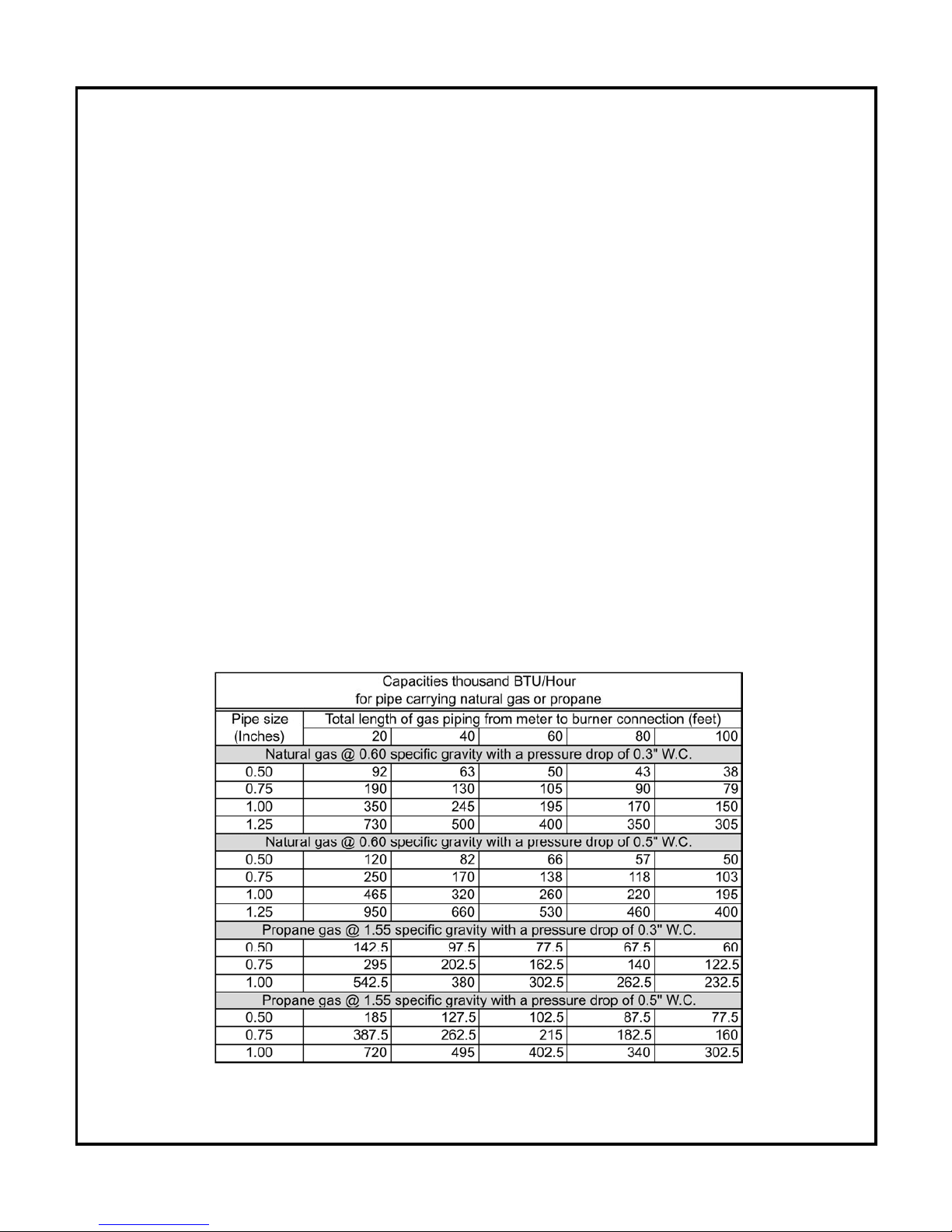
1. If possible, install a new gas line directly from the gas meter. If you are using an
existing gas line, verify it is clean and in good condition and verify it is large
enough to handle the load of all connected appliances. See the table below for
guidance on pipe sizes.
2. When branching from a common gas line, do not tap from the bottom or
horizontal sections, only from the side or top.
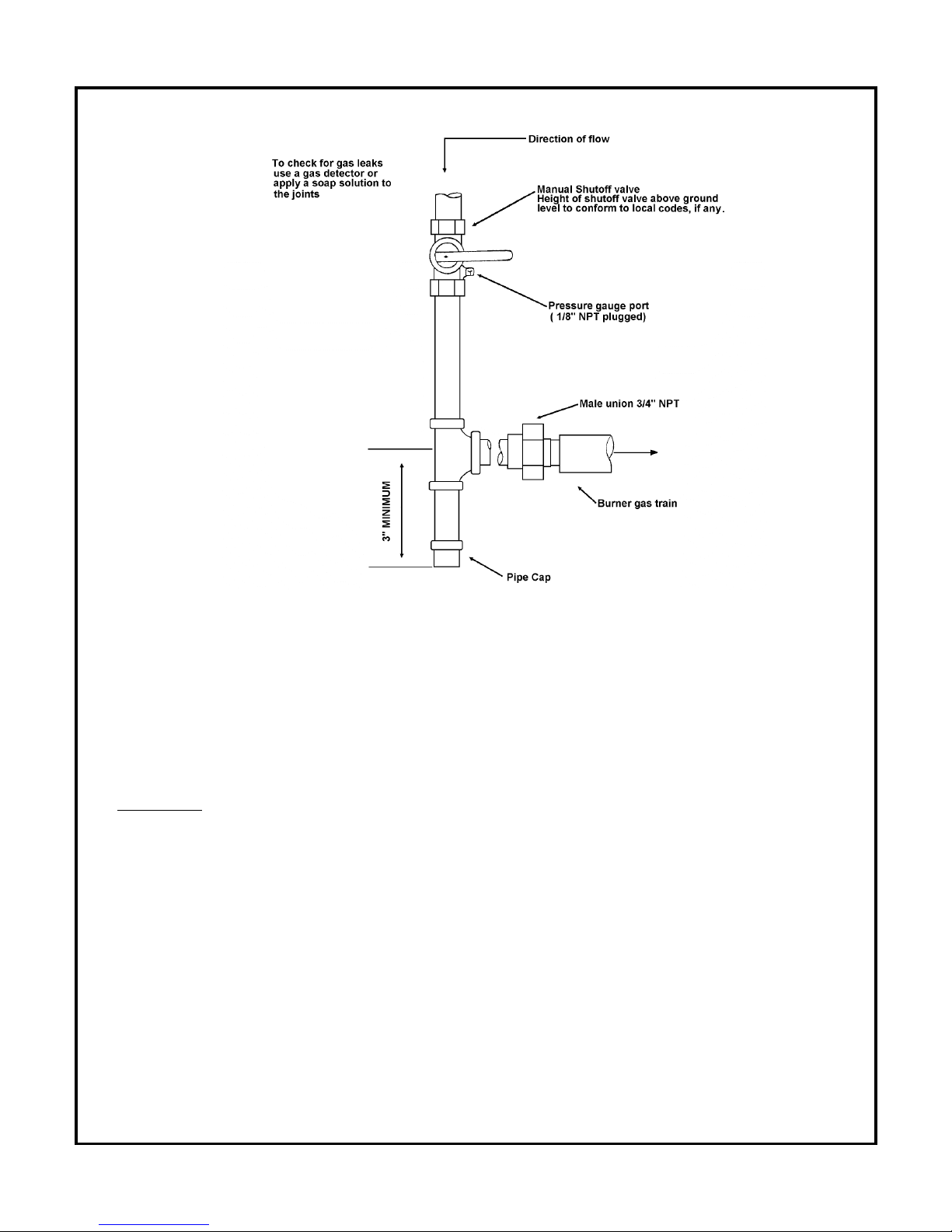
3. Install a main manual shutoff valve, sediment trap and ground joint union near the
burner combination gas valve connection as shown below.
Page 20
19
4
. GAS SUPPLY PRESSURE
• Maximum supply pressure: 14 inches W.C.
• Minimum supply pressure: 5” inches W.C.
WARNING:
• Do not expose the combination gas valve to gas pressures in excess of 14” W.C.
The valve has a safety mechanism that interrupt the flow of gas over 14” W.C. In
any event higher pressure could damage the valve seat, resulting in potentially
hazardous conditions. When pressure testing at higher pressures, disconnect
burner from gas line before testing.
Page 21
20
• If
the gas supply pressure can exceed 14 inches of water column at any time,
you must install a lockup type gas pressure regulator in the gas supply piping,
ahead of the main manual gas valve on the burner.
• The boiler and its gas connections must be leak tested before placing the boiler
in operation.
• Enough combustion air should be provided to the gasfired boiler in
accordance with the section “Air for combustion and ventilation” of the National
Fuel Gas Code ANSI Z223.1/NFPA 54 or clause 8,2, 8,3 or 8.4 of Natural gas
and Propane installation code CAN/CSA B149.1, or applicable provisions of the
local building codes.
TEST AND PURGE GAS LINE
1. Read warning above.
2. Pressure test and purge the line. The gas supplier or utility, following all
applicable codes, should do pressure testing.
Page 22
21
8
.0 ACCESSORY INSTALLATION
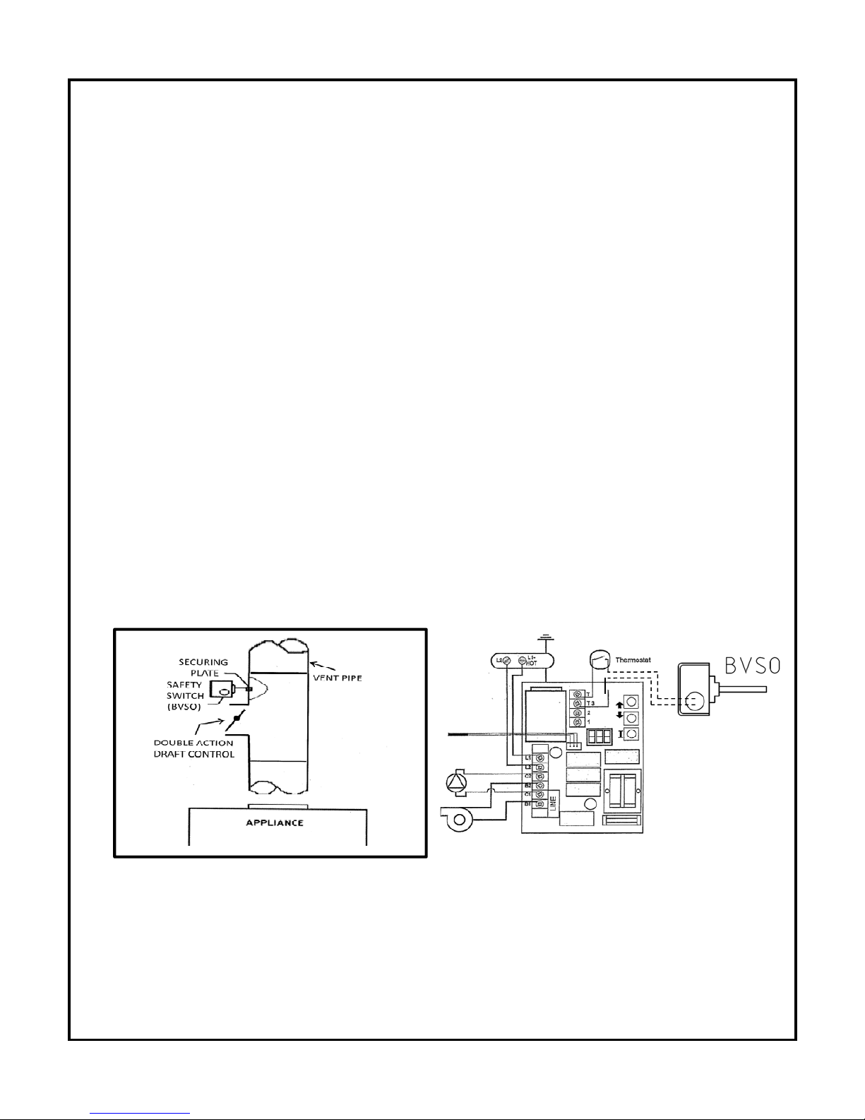
BLOCKED VENT SWITCH (BVSO) FOR CANADIAN APPLICATION ONLY
Gas-fired appliances installed in Canada require a blocked vent switch system when installed
on a chimney. A safety switch is included with the boiler to perform this function. It is the
installer’s responsibility to install the switch in accordance with the instructions provided. Not
applicable for Direct Vent systems. Field Controls Model: WMO-1 (Manual Reset)
Switch Operation
Blocked vent switches are flue gas safety devices for detecting spillage of flue gases due to a
b
locked flue or inadequate draft. After detecting a problem, the switch de-energizes the
system’s burner control. On gas-fired Boilers, the BVSO acts as a spill switch on the outlet of
the double acting draft-regulator.
NEVER reset the switch unless the cause of the blockage has been corrected.
Installation on Gas-Fired Boilers (Figure 1)
1) Drill a 5/8” hole in to the flue vent pipe near the appliance breech connection.
2) This hole must be before the draft regulator, vertically or horizontally.
3) Remove one of the securing nuts from the threaded tube of the safety switch.
4) Tighten the other securing nut onto the pipe as far as possible.
5) Insert the threaded tube end into the pierced hole of the flue vent pipe.
6) Install the securing nut on the safety switch tube, which protrudes into the flue vent pipe.
Tighten the nut securely.
Figure 1- Illustration Granby Industries Figure 2- BVSO wiring diagram
Installation on Gas-Fired Heating Units (Figure 1)
Page 23
22
W
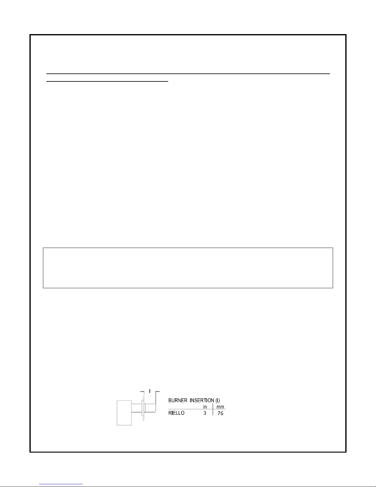
iring BVSO (Figure2)
The BVSO is connected in series with the call for heat device (24Vac), typically a room
thermostat or a zone valve end switch
Caution: Disconnect the electrical power when wiring the unit.
Wire the blocked vent switch in accordance with The National Electrical Code and applicable
local codes. Wire the blocked vent shut off switch (BVSO) in series with the thermostat and
the aquastat control (Figure 2).
S
ystem Test Procedure (BVSO)
1) With the power re-established, block the chimney or vent pipe downstream of the switch.
2) Adjust the thermostat to call for heat.
3) Once the heating system has started the blocked vent switch should shut down the burner
within 10 minutes or sooner.
4) Once the system has cooled, the blocked vent switch can manually be reset.
5) This procedure should be tested a second time.
6) After testing the blocked vent switch the chimney should be cleared of obstruction and the
heating system should be tested over a long run cycle.
If the block vent switch shuts down the system, check to ensure there is enough draft in the
chimney and venting pipes.
IN THE EVENT OF YOUR SYSTEM SHUTTING DOWN BECAUSE OF A BVSO DEVICE
OPERATION, THE LIKELY CAUSE IS FLUE VENT OR CHIMNEY BLOCKAGE. DO NOT
ATTEMPT TO RESTART THE SYSTEM. CONTACT A QUALIFIED SERVICE TECHNICIAN
WHO WILL ADDRESS THE ROOT CAUSE OF THE BVSO SHUTTING DOWN YOUR
BOILER
9.0 BURNER INSTALLATION AND SETTING
ASSEMBLY & INSTALLATION OF BURNER
ASSEMBLY Check that the burner model is correct for boiler rating required.
Assemble as per burner manufacturer’s instructions.
See burner manufacturer’s instructions for correct setting
INSERTION
Page 24

23
9.1 GasFired Boilers
CONSULT THE BURNER INSTRUCTION MANUAL THAT IS INCLUDED IN THE BURNER
BOX. In case of differences between the instructions on the burner instruction manual
and this manual, the boiler instruction manual (this manual) must be followed. The
instructions in the gas burner instruction manuals are detailed mounting, wiring,
adjusting, testing and maintenance instructions that are specific to the burner used
(Riello or Carlin). The specific adjustments specific the boiler are detailed in section
10 below. As a general guideline:
1) Use the burner instruction manual for general instructions.
2) Use this manual for specific instructions (such as for example, the initial air
gate adjustment for a specific size of boiler with a specific burner).
• RIELLO GAS BURNERS
o In the Section “Setting the burner”, disregard the table and use the initial
adjustments detailed for the appropriate boiler with Riello burner in the
section 10 of this manual below.
o In the section “Air gate adjustment”, disregard the table and use the
information in section 10 below.
o In the section “Combustion head settings”, disregard the table and use
the information in section 10 below.
o In the section “Manifold pressures”, disregard the table and use the
information in section 10 below.
o Disregard the “Pressure working chart” and the “Combustion chamber
size” sections as those sections apply only for conversion burners.
• CARLIN GAS BURNERS
o Disregard Table 1 on page 7; use the information in s
ection 10 instead.
COMBUSTION CHECKS
All combustion checks must be performed with an instrument capable of reading at
least CO2, CO and temperature.
Page 25

24
• R
IELLO GAS BURNERS
o Natural Gas Maximum CO2 is 10%
o Propane Gas Maximum CO2 is 12%
o Maximum Air free PPM reading of CO is 200.
o If any of these readings exceed the values above, adjust the air gate to
increase the air intake to the burner.
• CARLIN GAS BURNERS
o Natural Gas Maximum CO2 is 10.4%
o Propane Gas Maximum CO2 is 11.8%
o Maximum Air free PPM reading of CO is 50.
o If any of these readings exceed the values above, adjust the air gate to
increase the air intake to the burner.
AFTER PLACING THE BOILER IN OPERATION, THE IGNITION SYSTEM MUST BE
TESTED.
THE METHOD OF TESTING IS AS FOLLOWS:
• Place the boiler in operation, by raising the thermostat, and observe a
normal ignition of the burner.
• Lower the thermostat. This should shut off the burner.
• Close the manual shutoff gas valve that is upstream of the gas control.
• Place the boiler in operation again, by raising the thermostat.
• After a trial for ignition period, the burner control should go in lockout
mode. A light on the red button on the burner ignition control will indicate
this.
• To restart the boiler, open again the manual gas shutoff valve that you
closed a few steps back, press the red button on the ignition control, the
burner then should retry its ignition. If this sequence is not respected,
consult the burner manual.
Page 26
25
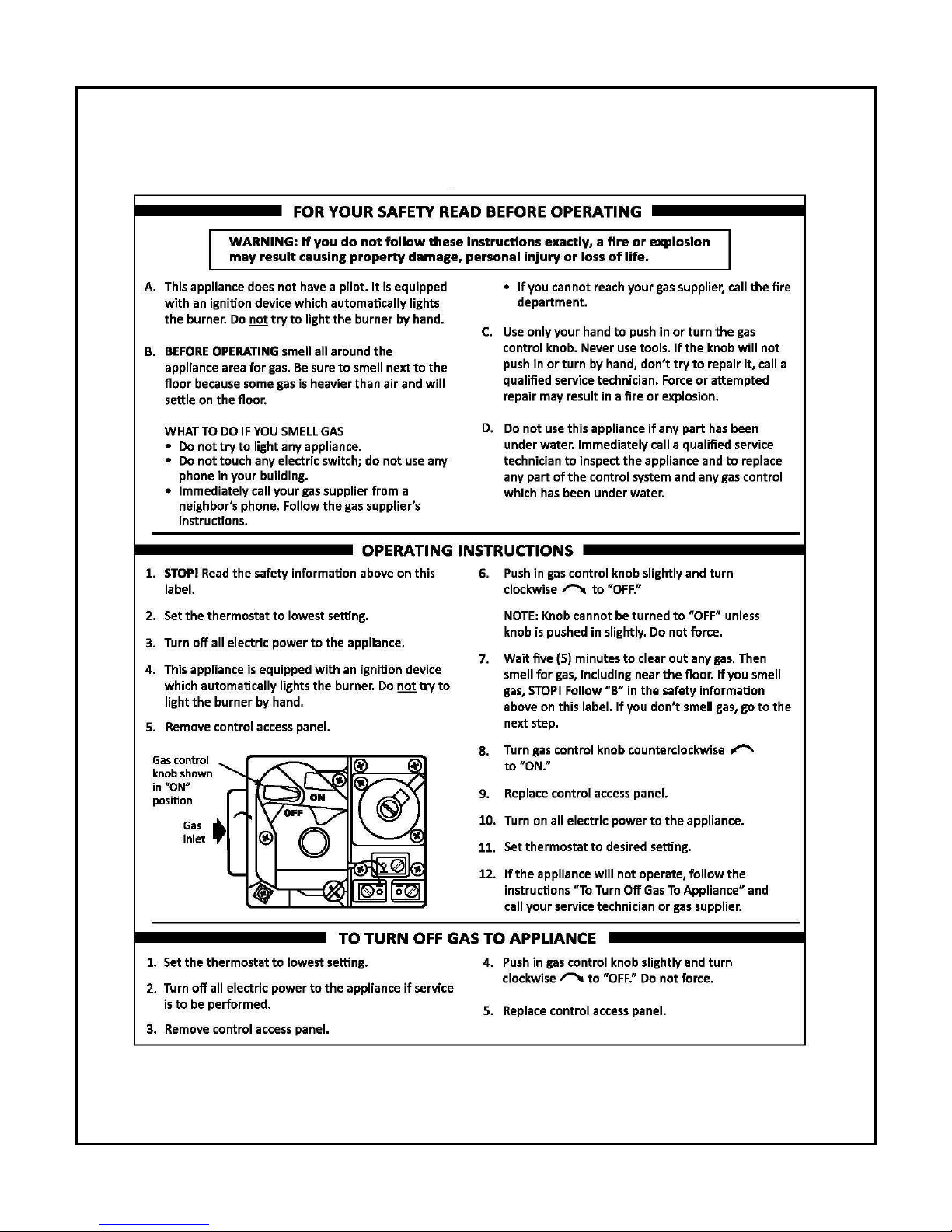
9.2 GASFIRED BOILER LIGHTING INSTRUCTIONS
Page 27
26
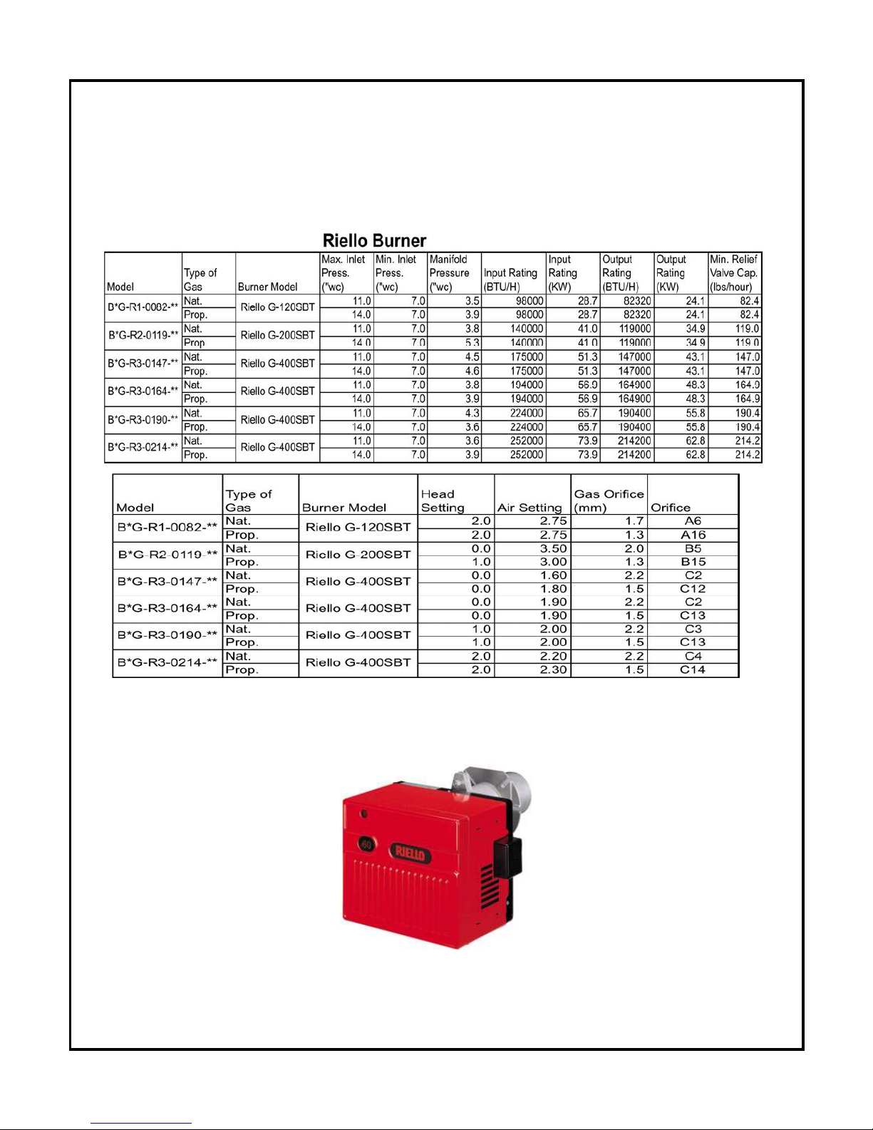
10.0 TECHNICAL INFORMATION
• *
* Honeywell control L7248 (high limit only, cool start application)
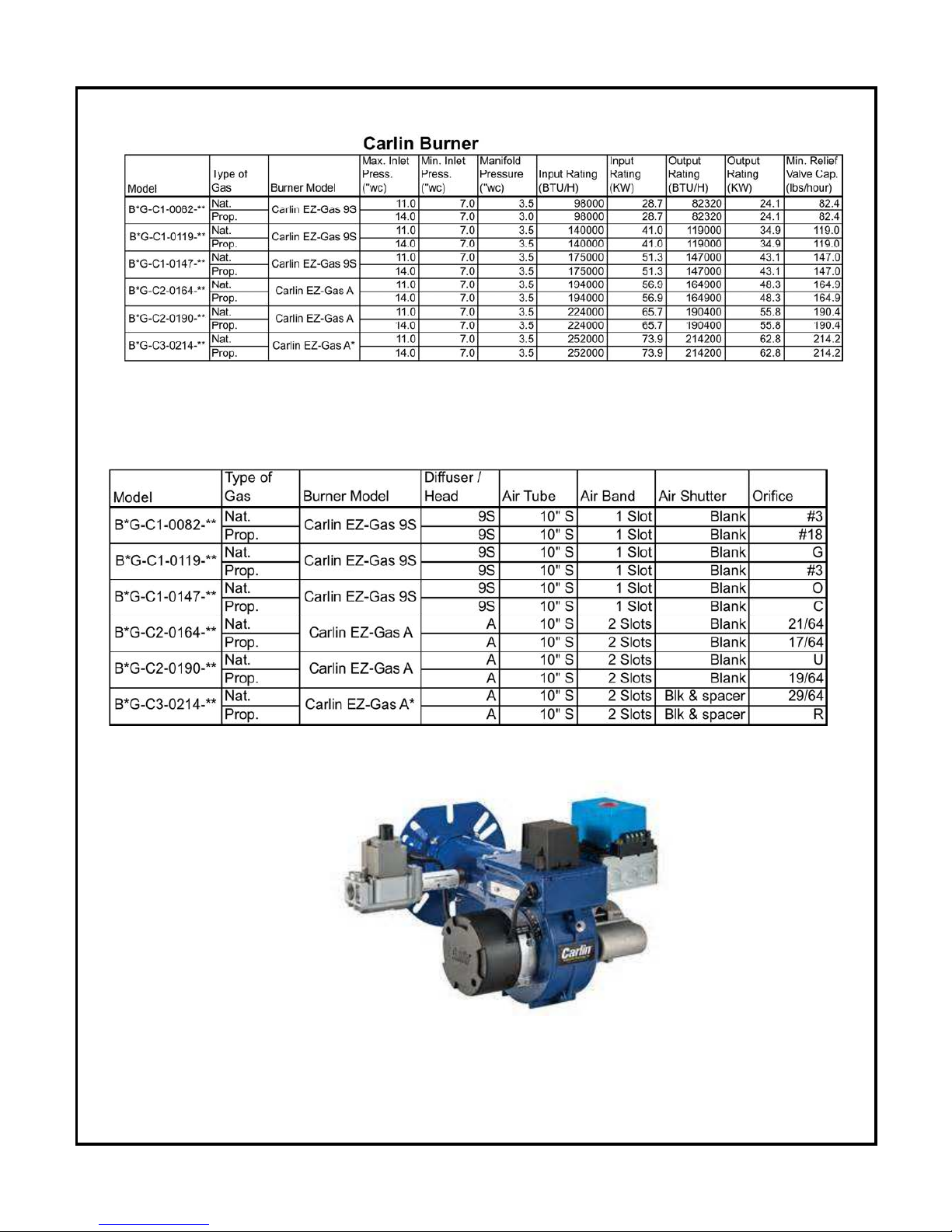
10.1 GasFired Boilers
Riello Gas Burner
Page 28
27
C
arlin Gas Burner
1
0
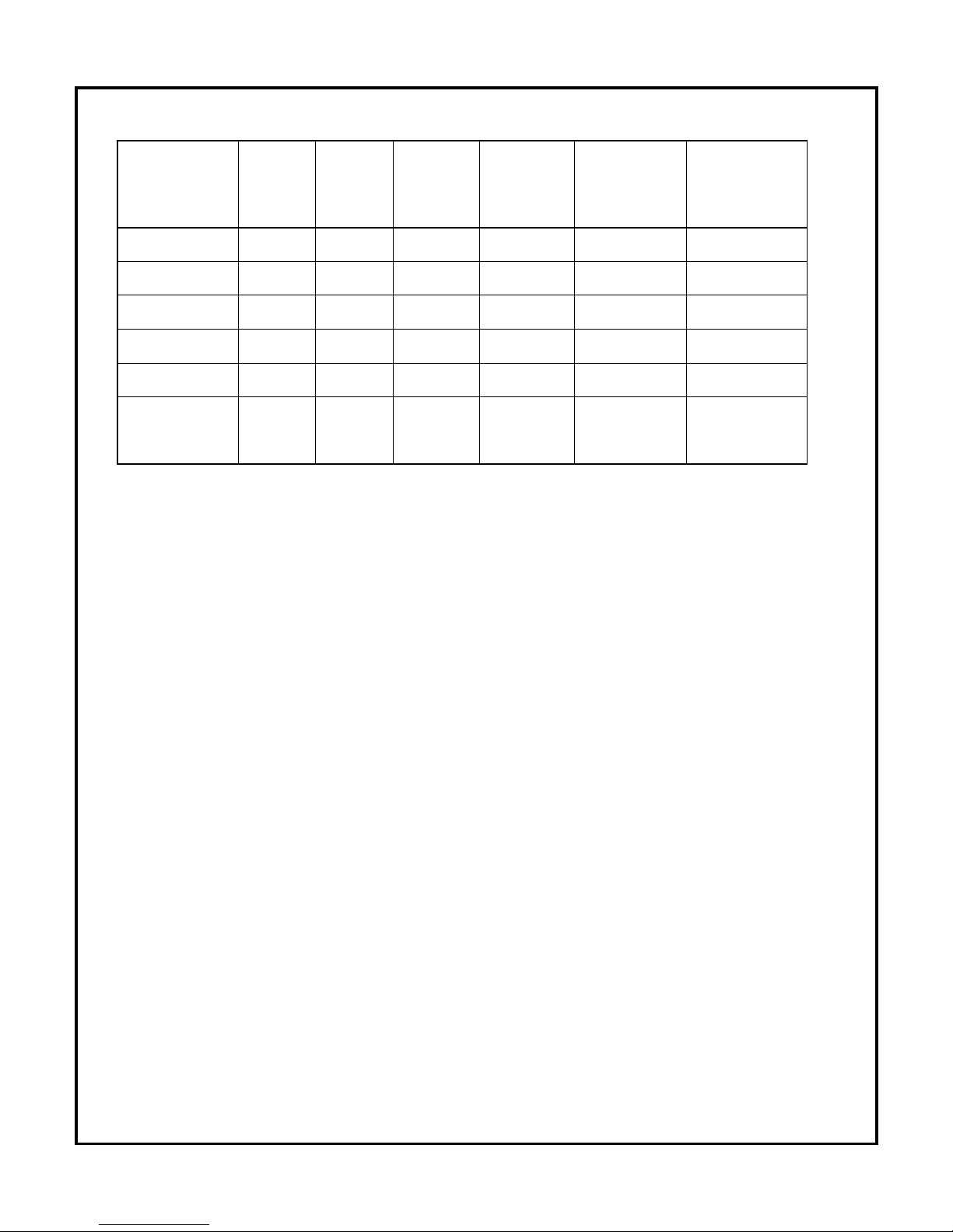
.2 Boiler Info
Page 29
28
GRANBY B*G CAST IRON SERIES
Appliance
Model
No. de
section
Length
(inches)
Shipping
weight
(lbs)
Water
Content
(gal.)
Supply Outlet
(inches)
Return Outlet
(inches)
B*G – E6-0085-**
3 18-7/8" 370 5.5 1-1/4" 1-1/4"
B*G – E7-0121-**
4 22-1/2" 437 6.9 1-1/4" 1-1/4"
B*G –E7-0152-**
5 26-3/4" 503 8.2 1-1/4" 1-1/4"
B*G – E7-0174-**
6 31-1/8" 569 9.5 1-1/4" 1-1/4"
B*G – E8-0194-**
7 35-1/2" 639 10.8 1-1/4" 1-1/4"
B*G – E8-0224-**
8 39-3/4" 705 12.2 1-1/4" 1-1/4"
WARNING: Do not operate if any controls have been submerged. Contact a
qualified technician for inspection prior to use.
11.0 BOILER START UP AND OPERATION
11.1 START UP PROCEDURE
• P
rior to start up make sure the service switch is in the OFF position.
• Check all fittings and wiring.
• Insure that the boiler and the entire heating system are completely filled with water
and that all air has been purged from the system resulting that proper system
pressure is achieved. The minimum PSIG is 12.
• Open all manual shutoffs throughout the system.
• Set operating controls to the recommended settings.
• Follow the burner manufacturer’s instructions for proper light off and setting.
Using accurate combustion test equipment set the burner for proper “steady
state” operation. The use of accurate instruments is necessary to achieve
maximum efficiency.
• Adjust the thermostat to manufacturer’s instruction
Page 30
29
• P
lace this manual, the control manual and the burner manual along with related
consumer information in an easily accessible location. Installers should make the
consumer aware of the content and location of this information.
11.2 Honeywell control L7248 - Adjusting Settings
- To discourage unauthorized changing of Aquastat settings, a procedure
to enter the ADJUSTMENT mode is required.
- To enter the ADJUSTMENT mode, press the UP, DOWN and I buttons
simultaneously for three seconds.
- Press the I button until the feature requiring adjustment is displayed then
press the UP and/or DOWN buttons to move the set point to the desired
value.
Note: After 60 seconds without any button inputs, the control will automatically
return to the RUN mode and lock the setting.
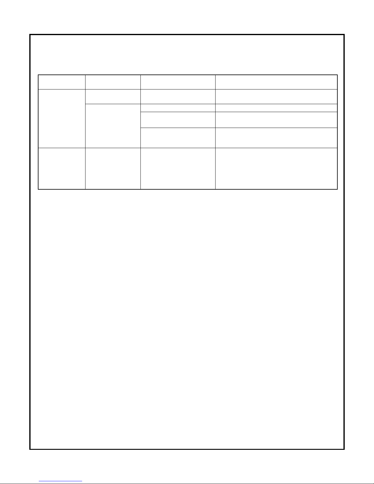
Error Codes
W
hen attempting to diagnose system performance, reference to the LED display can help to
identify specific areas not working properly. The LED display will scroll ERR, followed by a
digit (1-8). Refer to the information inside the cover of the control L7248.
Err 1 Sensor fault Check sensor
Err 2 ECOM fault
Check Optional EnviraCOM
wiring
Err 3 Hardware fault Replace control
Err 4 B1 fault Check B1 wiring/voltage
Err 5 Low line Checl L1 - L2 > 110 V a/c
Err 6 Fuse
Check ECOM wires, replace
fuse
Err 7 EEPROM Reset limit values
Err 8 Multiple Err 4
Press/Hold
I for 60 sec
min*
Page 31
30
1
1.3 Trouble shooting the control
System
Condition
Diagnostic
Condition
Check Action
Boiler is cold,
house is cold.
Display is OFF 120 V a/c System power. Turn system power on
Display is ON 24 V a/c T-T No 24 V; replace control
24V present; disconnect
thermostat, short T-T
Boiler starts, check wiring and thermostat.
120 V a/c at B1-B2
.
If no, replace control.
. If yes, check burner and wiring.
Boiler is hot,
house is cold.
Display is ON. 120 V a/c at C1-C2
.
120 V a/c at C1-C2, check wiring to
pump.
Wiring OK , is pump running ?
.
If not, replace the pump.
. If pump is running, ch
eck for trapped air
or closed zone valves.
TESTING SAFETY AND CONTROL DEVICES
In the event the boiler is equipped with a low water cut off, the cut off should be
tested in accordance with the manufacturer’s recommendations. When no
instructions are available follow the guidelines in ASME CSD-1 or perform the
following procedures:
• Set room thermostat at least 10°F above room temperature.
• With Burner operating, drain boiler slowly until the burner shuts off. This shut
off should occur when the water level falls below the low water cut off probe.
• Check to be sure the burner shut off is not due to an open limit or flame
safety issue.
• Reset the room thermostat to the desired temperature and refill the boiler
Page 32
31
12.0 MAINTENANCE / SERVICE
Your heating appliance is designed to be maintained and serviced only by your heating
p
rofessional. The following sections provide information on maintenance and service
related activities. In the event a problem occurs consult your heating professional
C
ONDENSATION
If you have condensation in your chimney, make sure that the chimney size is according
to the tables in CSA B139. Insulating the flue pipe between the furnace and the chimney
base can increase the temperature at the entrance of the chimney. If this is not
sufficient, consider cutting or removing some flue baffles in the furnace. BE AWARE
THAT REMOVING BAFFLES REDUCES THE UNIT EFFICIENCY AND A MODIFIED UNIT IS
NO LONGER ENERGY STAR APPROVED.
HOMEOWNER SERVICE CAUTION
In the event of a problem with the heating system the homeowner should perform
the following limited activities.
• Check to make sure that there is fuel in the tank and that oil valves are open.
• Set the thermostat above existing room temperature.
• Check for blown fuses or circuit breakers and make sure power switches are
in an on position.
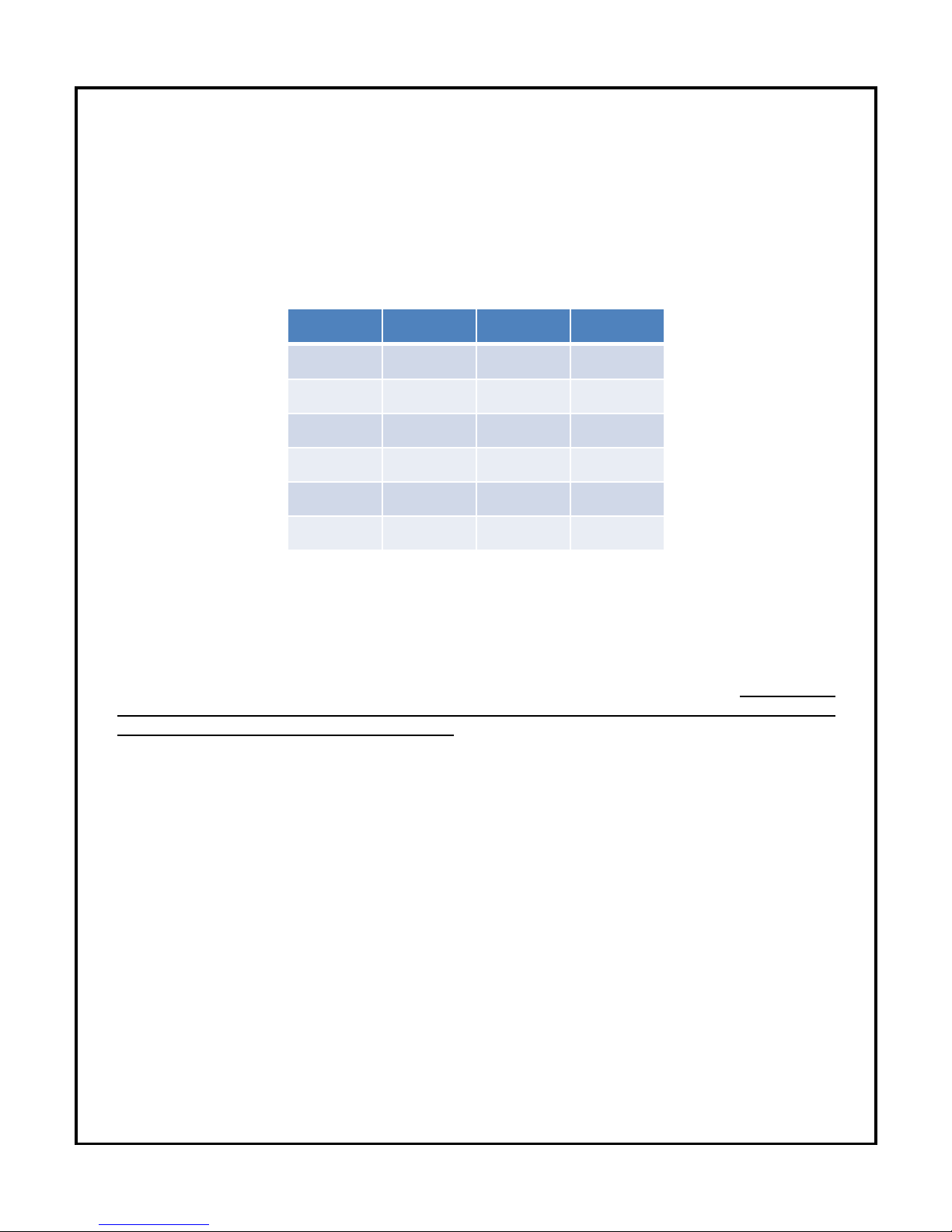
• NEVER TAMPER WITH CONTROLS, WIRING OR PIPING !
Model
# Of Baffles
2
nd
Pass 3rd Pass
3 Sections
4 X X 4 Sections
4 X X 5 Sections
2
X 6 Sections
2
X 7 Sections
2
X 8 Sections
2
X
Page 33
32
12.1 CLEANING THE BOILER
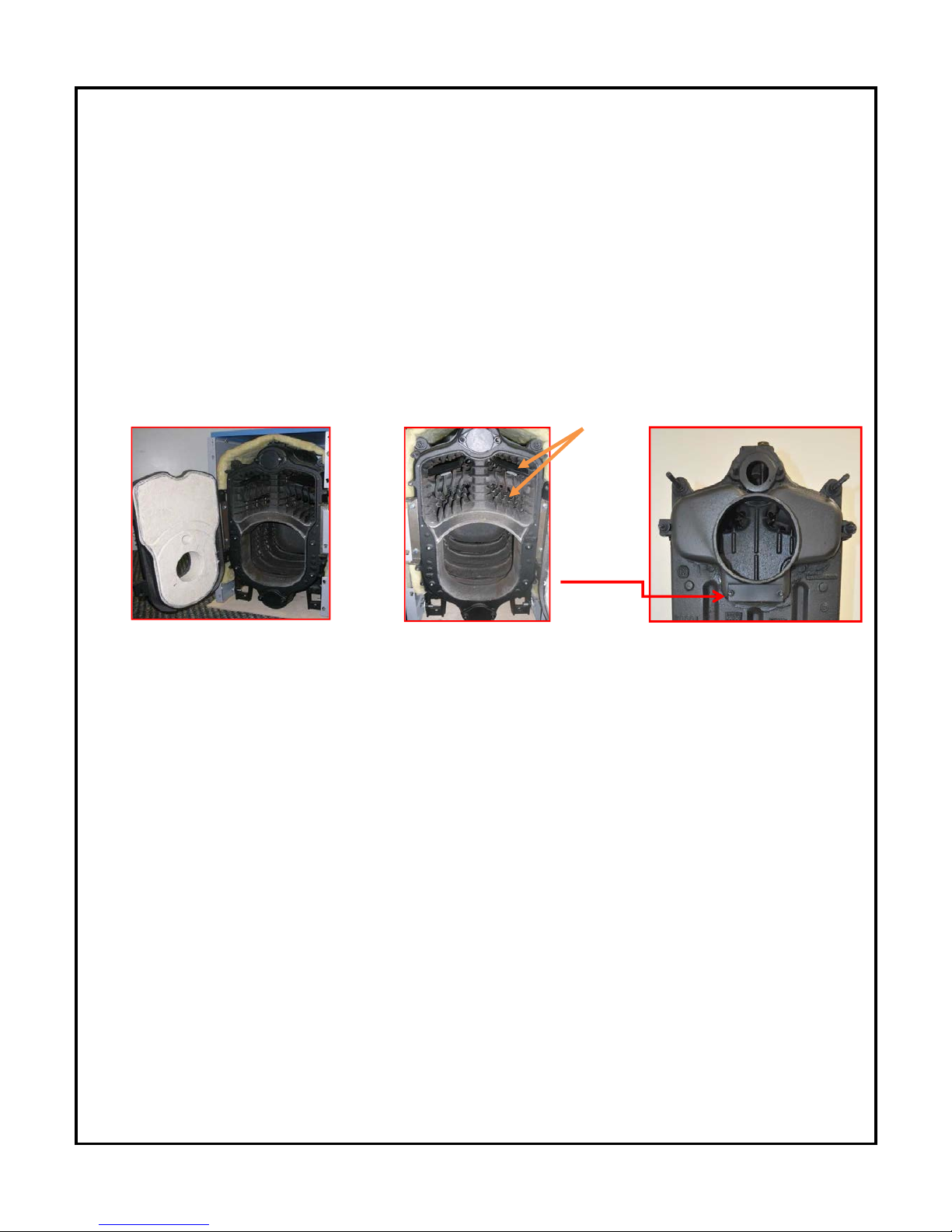
Section cleaning should only be performed by a service technician and must only be performed
w
hen the boiler is out of service. The following steps should be followed:
• Remove the 2 front panels by sliding it upwards to release and then pull to remove.
• Open the front swing door by removing the four bolts; this will expose the chamber area as
well as the second and third passes. (A)
• Remove the stainless steel baffles. With a cleaning brush clean the boiler section, second
and third passes. (B)
• Remove insulation and the smoke hood cleaning access door from the rear section.
R
emove any soot that may have collected in the smoke hood. (C)
Baffles
cleaning
C access
door
A B C
•
Replace insulation on the rear section and smoke hood.
• Replace swing door and tighten bolts.
• Refit the front casing.
SPECIFIC TO INSPECTION AND SERVICE OF GASFIRED BOILERS
• The vent system must be inspected annually.
• If a low water cutoff is installed in the system, it must be inspected annually.
• The burner flame in operation must be checked regularly. It should be mostly
blue with some yellow tipping permitted.
• Check to make sure that the flow of combustion air to the burner is not
obstructed.
• Verify proper operation of the boiler after servicing
Page 34
33
12.2 BURNER CLEANING NOTES
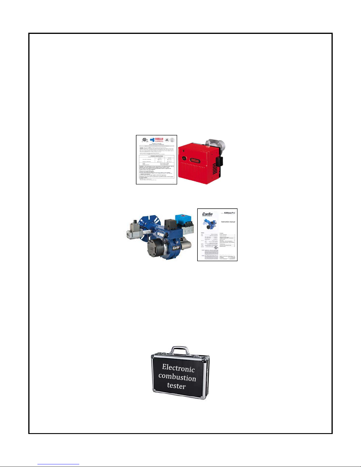
Your burner manufacturer has supplied instructions for servicing and
m
aintenance should be performed as instructed.
Riello 40 G120 Gas Burner
____________________________________
Carlin EZGas PRO Burner Burner
12.3 PERFORM COMBUSTION TEST
Perform an annual combustion check on the gas burner.
Page 35
34
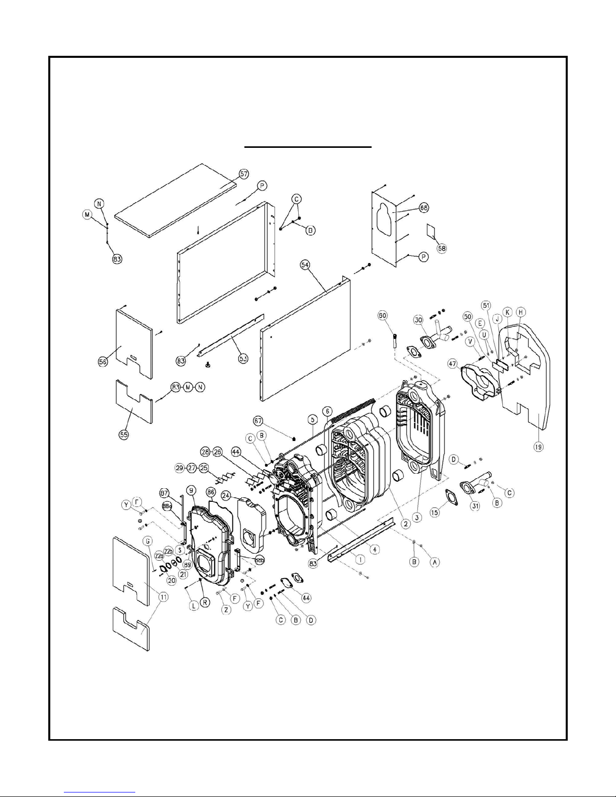
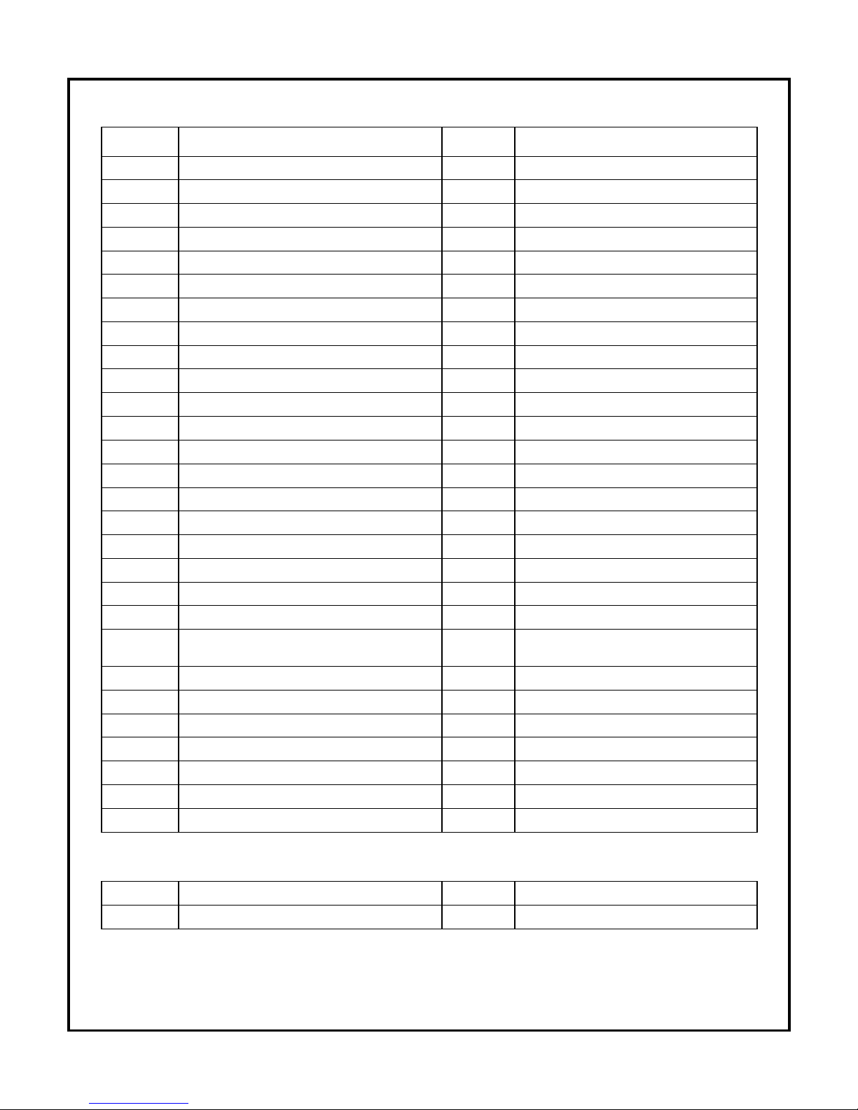
13.0 EXPLODED PARTS VIEW
Exploded Parts View
Page 36
35
Part List
1 G*C FRONT SECTION 60 GC PNA - POCKET FOR SENSING BULBS
2 G*C INTERMEDIATE SECTION 67 TAPPING WITH AIR RELIEF VALVE
3 G*C REAR SECTION 68 REAR CASING
4 NIPPLE 83 SPECIAL PIN FOR CASING ASSEMBLY
5 STAYBOLTS 86 FIBRE-GLASS ROPE DIA. 10
6 BODY INSULATION 87 HINGE PIN
9 FRONT DOOR (MONOBLOCK) 88a HINGE - LEFT HAND SIDE
11 FRONT INSULATION 88b HINGE - RIGHT HAND SIDE
15 RUBBER GASKET 89 OUTLET FOR PRESSURE MEASUREMENT
19 REAR INSULATION A SETSCREW M10 x 30
20 SIGHTGLASS FRAME B WASHER A10.5
21 SIGHTGLASS C NUT M10
22a SIGHTGLASS FRAME INSULATION D STUD M10 x 40
22b SIGHTGLASS INSULATION E NUT M8
24 FRONT DOOR REFRACTORY F WASHER A8.4
25 / 27 / 29 2ND PASS RETARDERS G SETSCREW M5 x 15
26 / 28 3RD PASS RETARDERS H NUT M6
30 DELIVERY STUB PIPE J WASHER A6.4
31 RETURN STUB PIPE K STUD M6 x 22
44 BLANK FLANGE L SELF TAPPING SCREW S6.3 x 30
47 SMOKEHOOD DIA.150 MM M SERRATED WASHER A4.3
50
SMOKEHOOD CLEANING COVER
INSULATION
N NUT M4
51 SMOKEHOOD CLEANING COVER P SELF TAPPING SCREW S4.8 x 9.5
53 CHASSIS - LEFT/RIGHT HAND SIDE R WASHER A6.4
54 SIDE CASINGS - LEFT/RIGHT HAND SIDE S SETSCREW M3 x 6
55 FRONT CASING LOWER PART U WASHER A9
56 FRONT CASING UPPER PART V STUD M8 x 50
57 ÜST SAC Y SETSCREW M8 x 16
58 BOILER DATA PLATE Z SETSCREW M8 x 30
PARTS NOT ILLUSTRATED
AA HONEYWELL L7248 - AQUASTAT CC PRESSURE VALVE (30 lbs)
BB PRESSURE – TEMPERATURE GAGE DD DRAIN VALVE
Page 37
36
G
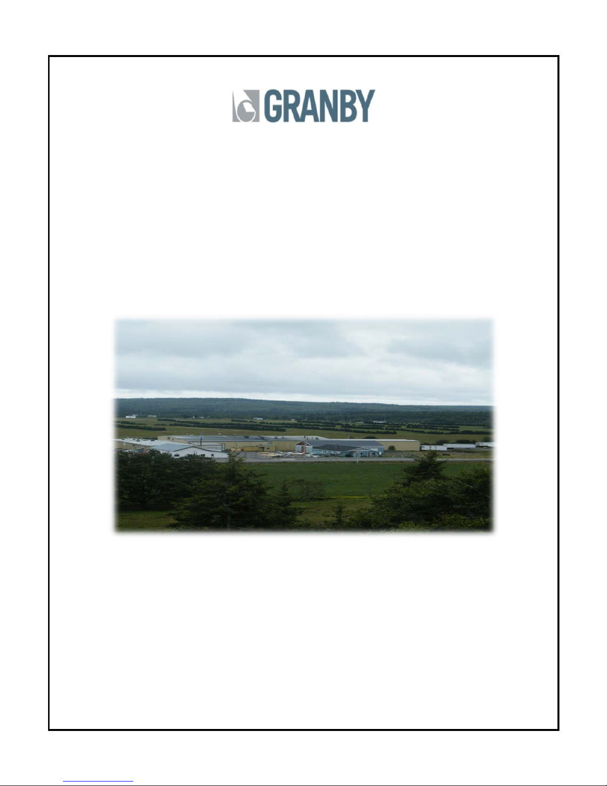
ranby Furnaces Inc. manufactures a full line of oil and gas-fired
boilers in its 70,000 square feet facility. Granby products are sold
across Canada and the United States through a distribution
network.
Our team of engineers, designers and technicians continually
research and develop products to go beyond the demanding
specifications of today’s certifications.
Thank you
T
hank you Thank you
Thank you for choosing Granby
for choosing Granbyfor choosing Granby
for choosing Granby....
 Loading...