

Granby B*G-3, B*G-4, B*G-5, B*G-6, B*G-7 Installation, Operation And Service Manual
...
Installation, Operation and
Service Manual
Cast Iron Boiler SERIES
B*G, 3 sections illustration
INSTALLATIONS MUST MEET ALL LOCAL AND FEDERAL
CODES THAT MAY DIFFER FROM THIS MANUAL
THE FOLLOWING PAGES INCLUDES WARNINGS, INSTALLATION AND MAINTENANCE
INSTRUCTIONS SPECIFIC TO GAS-FIRED UNITS. PLEASE REVIEW THIS MANUAL
CAREFULLY IF YOUR BOILER IS NATURAL GAS-FIRED OR PROPANE GAS-FIRED
Please read the manual in its entirety before beginning installation.
This manual must be kept with the boiler for future reference.
GRANBY FURNACES INC.
PO Box 637
12118 Hwy 209
Parrsboro Nova Scotia Canada
B0M 1S0
www.granbyindustries.com 04-07-2015 G2014-E5G Rev. D
Gas
-
Fire
B*G-3 sections
B*G-4 sections
B*G-5 sections
B*G-6 sections
B*G-7 sections
B*G-8 sections
* = Brand name, G=Gas

1
N
OTE:
THE BURNER INSTRUCTION MANUAL AND THE BURNER USER’S
INFORMATION MANUAL ARE CONSIDERED PART OF THIS MANUAL
AND THEIR INSTRUCTIONS MUST BE FOLLOWED EXCEPT WHEN
SPECIFICALLY MENTIONNED IN THIS MANUAL.
WARNING: If the information in this manual is not followed
exactly, a fire or explosion may result, causing property damage,
personal injury or death.
- Do not store or use gasoline or other flammable vapors or
liquid in the vicinity of this or any other appliance.
- WHAT TO DO IF YOU SMELL GAS
o Do not try to light the appliance,
o Do not touch any electrical switch; do not use any
phone in your building,
o Immediately call your gas supplier from an outside
p
hone. Follow the gas supplier’s instructions,
o If you cannot reach your gas supplier,
call the fire department.
- Installation and service must be performed
by
a qualified installer, service agency or the
gas supplier.

2
TABLE OF CONTENTS
B
*C - Gas
1.0 IMPORTANT SAFETY ADVICE 3
2.0 PRODUCT INFORMATION 4
3.0 UNIT INSTALLATION 5
3.1 PLACEMENT & LEVELING OF THE UNIT 5
3.2 JACKET ASSEMBLY & CONTROL INSTALLATION 5
4.0 PIPING 9
5.0 ELECTRIC WIRING 12
6.0 CHIMNEY INFORMATION 14
7.0 FUEL SYSTEM 17
7.1GAS-FIRED BOILERS 17
8.0 ACCESSORY INSTALLATION 21
9.0 BURNER INSTALLATION & SETTING 22
9.1 GAS-FIRED BOILERS 23
9.2 GAS-FIRED BOILERS LIGHTING INSTRUCTIONS 25
10.0 TECHNICAL INFORMATION 26
10.1 GAS-FIRED BOILERS 26
10.2 BOILER INFO 28
11.0 BOILER START UP & OPERATION 28
11.1 START UP PROCEDURE 28
11.2 L7248 HONEYWELL CONTROL 29
11.3 TROUBLE SHOOTING THE CONTROL 30
12.0 MAINTENANCE / SERVICE 31
12.1 CLEANING THE BOILER 32
12.2 BURNER CLEANING NOTES 33
12.3 PERFORM COMBUSTION TEST 33
13.0 EXPLODED PARTS VIEW 34

3
1.0 IMPORTANT SAFETY ADVICE
Please read and understand this manual before installing, operating or
s
ervicing the furnace. To ensure you have a clear understanding of the
operating procedures of the appliance please take the time to read section
IMPORTANT SAFETY ADVICE of this manual.
THE INSTALLATION OF YOUR GAS-FIRED BOILER MUST CONFORM TO THE
REQUIREMENT OF THE AUTHORITY HAVING JURISDICTION OR IN THE ABSENCE OF
SUCH REQUIREMENTS, TO THE NATIONAL FUEL GAS CODE ANDSI Z223.1/NFPA 54
AND/OR NATIONAL GAS AND PROPANE INSTALLATION CODE CAN/CSA B149.1.
WHERE REQUIRED BY THE AUTHORITY HAVING JURISDICTION, THE INSTALLATION
MUST CONFORM TO THE STANDARD FOR CONTROLS AND SAFETY DEVICES FOR
AUTOMATICALLY FIRED BOILERS ANSI/ASME CSD1.
SHOULD OVERHEATING OCCUR OF THE GAS SUPPLY FAILS TO SHUT DOWN, DO
N
OT TURN OFF OR DISCONNECT THE POWER SUPPLY TO THE CIRCULATOR,
INSTEAD SHUT OFF THE GAS SUPPLY AT A LOCATION EXTERNAL TO THE
APPLIANCE.
DO NOT USE THIS BOILER IF ANY PART HAS BEEN UNDER WATER. IMMEDIATELY
CALL A QUALIFIED SERVICE TECHNICIAN TO INSPECT THE BOILER AND TO
REPLACE ANY PART OF THE CONTROL SYSTEM AND ANY GAS CONTROL, WHICH
HAS BEEN UNDER WATER.
CAUTION
DO
NOT START THE BURNER UNTIL ALL FITTINGS, COVERS AND DOORS ARE IN
PLACE. DO NOT TAMPER WITH THE BOILER OR CONTROLS, CALL A QUALIFIED
BURNER TECHNICIAN. DO NOT STORE OR USE GASOLINE OR OTHER FLAMMABLE
VAPOURS AND LIQUIDS IN THE VICINITY OF THIS UNIT OR ANY OTHER APPLIANCE.
IMPORTANT
This manual contains instructional and operational information for the B*G GAS-FIRED boiler .
Read the instructions thoroughly before installing boiler or starting the burner. Consult local
authorities about your local FIRE SAFETY REGULATIONS. All installations must be in
accordance with local state or provincial codes. Improper installation will result in voiding of
warranty.
4
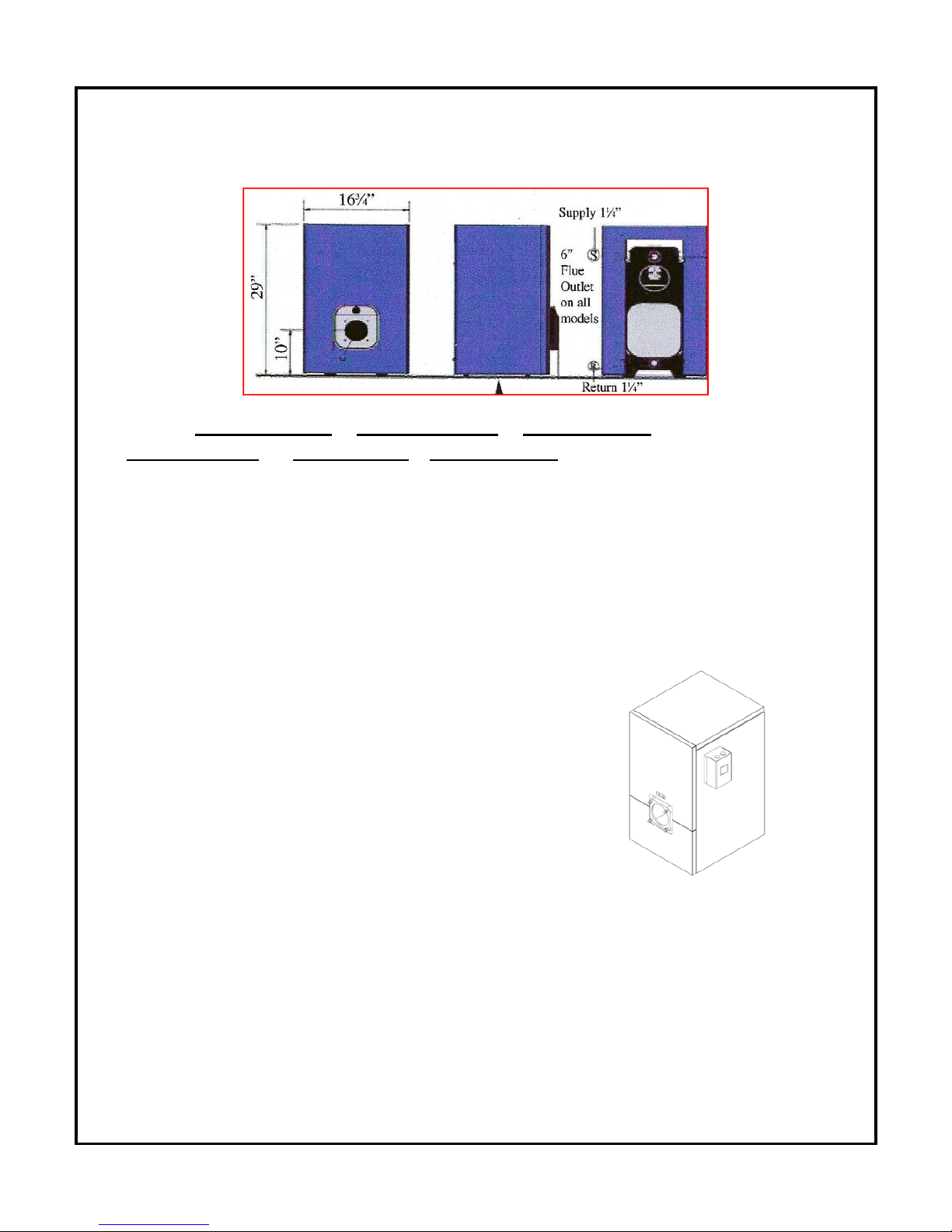
2.0 PRODUCT INFORMATION
PHYSICAL DIMENSIONS
Length : ( 3 sections 18 7/8 ‘’ ) ( 4 sections 22 1/2’’ ) ( 5 sections 26 ¼’’ )
( 6 sections 31 1/8’’ ) ( 7 sections 35 ½’’) ( 8 sections 39 ¼’’)
CLEARANCE
Proper clearances must be maintained not only from combustible materials but also to provide
adequate access for servicing. All installations must comply with local codes and CSA B149.1
(gas) in Canada and NFPA 54 (gas) in the United States. Consult local fire codes for required
clearances. Connections to chimney must be made with the proper gauge thickness and
diameter of fluepipe as required by CSAB149.1,NFPA 54, whichever is applicable.
CLEARANCE (minimum) FOR SERVICING – Gas
Front 24” (609 mm)
Rear 24” (609 mm)
Left Side 24” (609 mm)
Right Side 2” (50.8 mm)
Top 10” (254 mm)
CLEARANCE (minimum) TO COMBUSTIBLES – Gas
Top 10” (254 mm)
Front 24” (609 mm)
Rear 24” (609 mm)
Left Side 24” (609 mm)
Right Side 2” (50.8 mm)
Chimney Connector 9” (229 mm)
SPECIFIC TO GASFIRED BOILERS
*** A gasfired boiler must NOT be installed on carpeting.
D
RAFT PRESSURE
Breech draft pressure -0.02’’ w.c. – Gas-Fired Boiler

5
FLUE PIPE CONNECTION
GasFired boilers (C
HIMNEY ONLY applications)
CLEANOUTS
Rear removable smoke hood cover & Combustion Front Door Opening
FUEL
GasFired Natural Gas or Liquefied Petroleum Gas LPG
ELECTRICAL
CANADA : 120 Volts, 60Hz,15 amps fuse or breaker
U
SA : 13.3 amps, circuit protection 20 amps.
AIR SUPPLY
CAUTION: Adequate air supply for both combustion and ventilation must be available.
See page 17 for details.
3.0 Unit installation
3.1 PLACEMENT & LEVELING OF THE UNIT
The boiler should be located on firm foundation in an easily accessible area that meets the
previously discussed clearances and air requirements. In situations where the floor may be
uneven the unit may be levelled by using the leg levellers provided on the boiler or through the
insertion of shims under the legs.
3.2 JACKET ASSEMBLY AND CONTROL INSTALLATION
The boiler jacket has been designed for ease of assembly and removal. The following step-bys
tep process will ease installation. A screwdriver, 17 mm socket and ratchet or a 17 mm
wrench or adjustable wrench are needed.
Adjustable
Leg Leveler
Rail
6
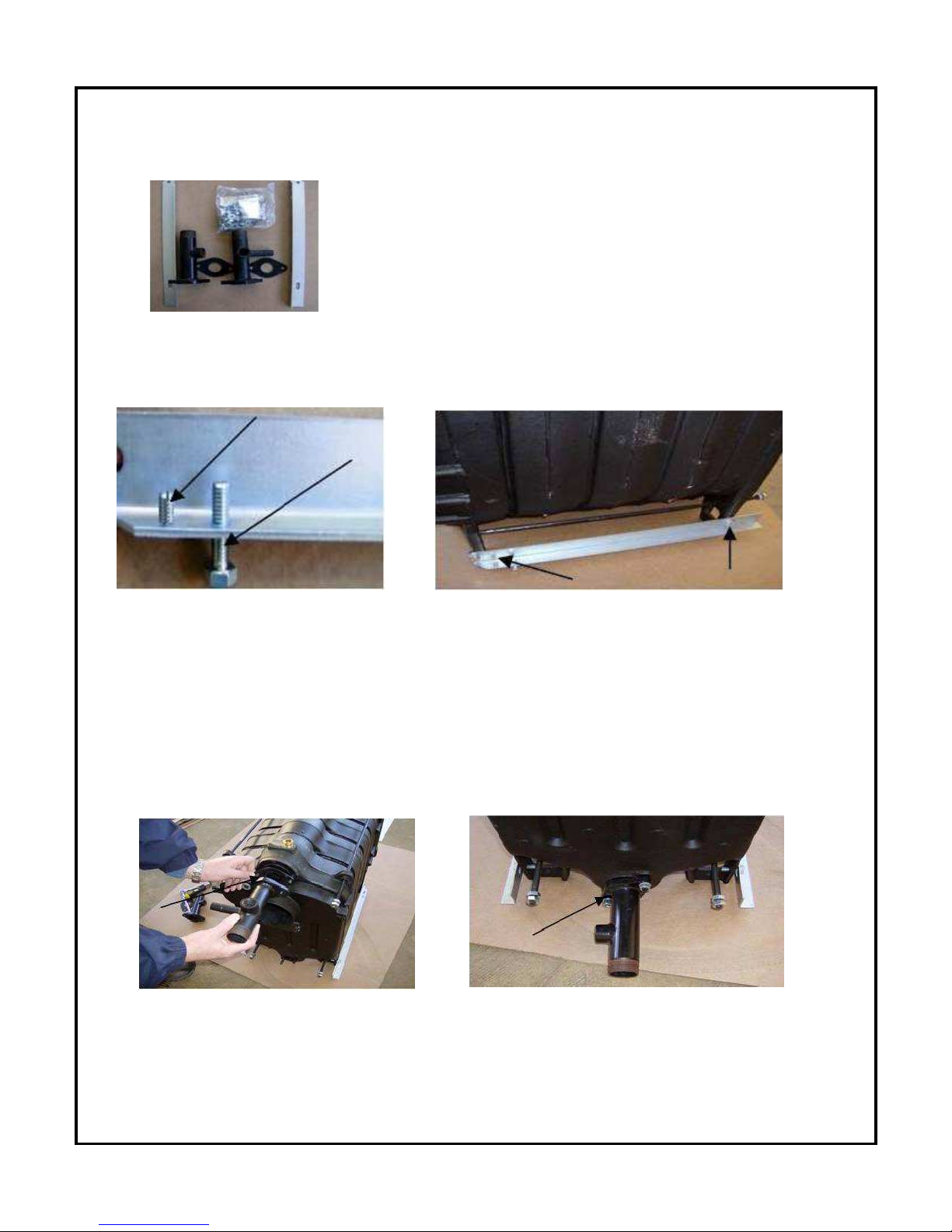
STEP 1 VERIFY CONTENTS OF JACKET ASSEMBLY PACKAGE.
Your jacket assembly will contain two (2) manifolds with gaskets, a
fastening package which includes all necessary bolts, screws, nuts
and washers for assembly along with burner studs, nuts and
washers, block insulation, rear of block insulation, aluminum faced
tape, levelling frame rails, two (2) side panels, a rear panel top
panel and re-insulated top and bottom front panels
S
TEP 2 FRAME RAIL CONNECTION
Attach 10 mm bolts to the underside of the frame rails. These will be used to level the boiler.
Screw the 4 mm jacket affixing screw to the frame rail from the top down. Both the bolt and
affixing screw will be located on the same end of the frame rail. The frame rail will then be
bolted to the legs of the boiler with the frame rail and containing the affixing screw facing in the
direction of the front end of the boiler.
S
TEP 3 MANIFOLD INSTALLATION
Using the gaskets and bolts supplied connect the manifolds directly to the boiler block. The
top supply manifold will have a 3/4” npt tapping for a relief valve and 1/4” npt tapping for a
gauge. The bottom return manifold has 3/4” npt tapping for a drain vlave. Both manifolds have
1-1/4” male npt threads for sytem connection.
7
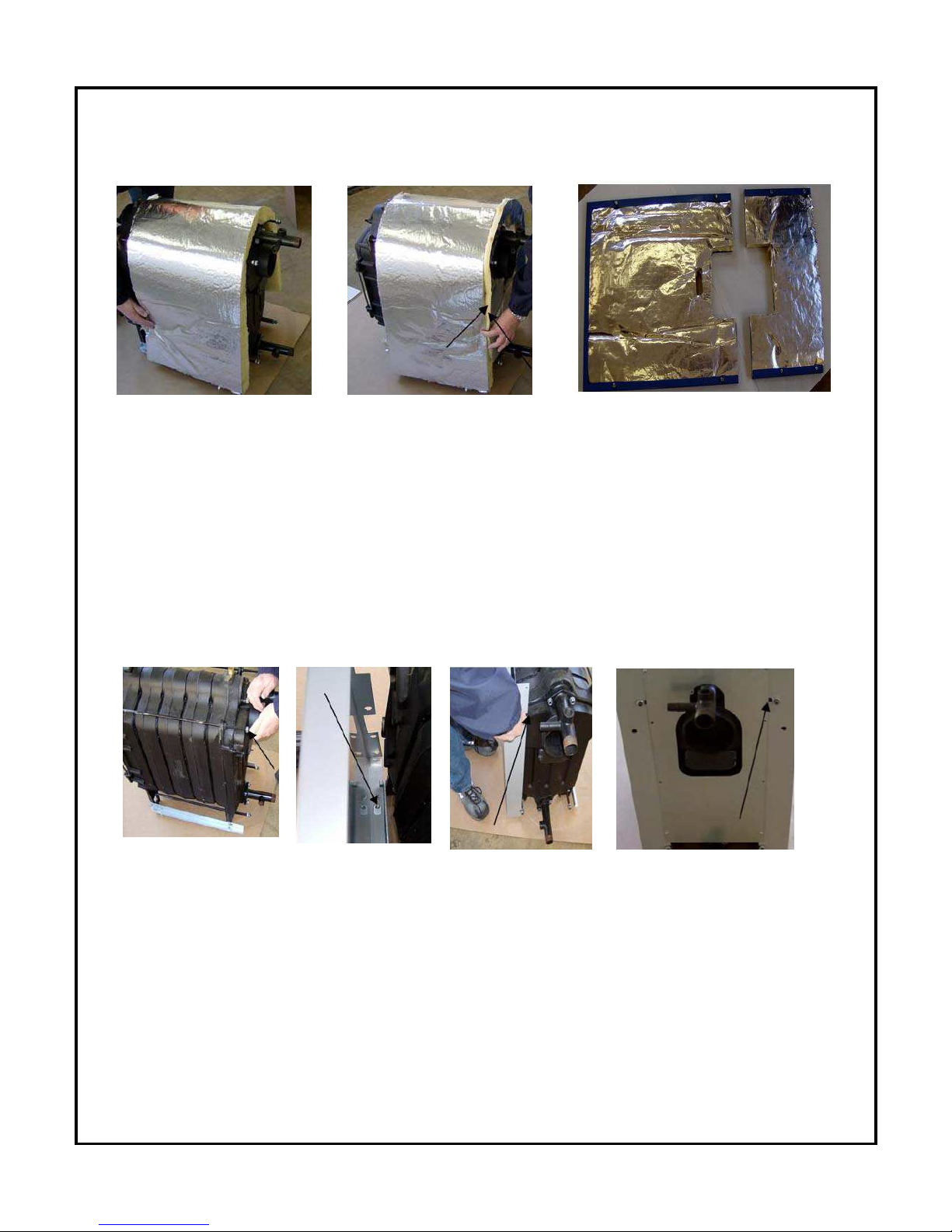
STEP 4 INSULATION INSTALLATION
Drape the large piece of block insulation directly over the block taking care to provide adequate
c
learance from frame rails. Using the aluminum faced tape attach the preshaped rear
inslulation to the block insulation. The process is simply taping the two pieces together. The
front panels come pre-insulated.
STEP 5 SIDE AND BACK PANEL ATTACHMENT
Affix panel mounting nuts to the rear of the tie rods. Mount the side panels by placing the
p
anel over the frame rail so that the hole in the bottom lip of the panel fits directly over the
jacket affixing screw on the rail. You can then lock the panel in place by sliding it slightly
forward. The slot on the rear of the panel will now be in position to slide over the tie rod at the
rear of the boiler. Tighten the nuts on the tie rod end to firmly secure the panel. Repeat on the
other side. Screw the back panel to the side panels.
¸
8
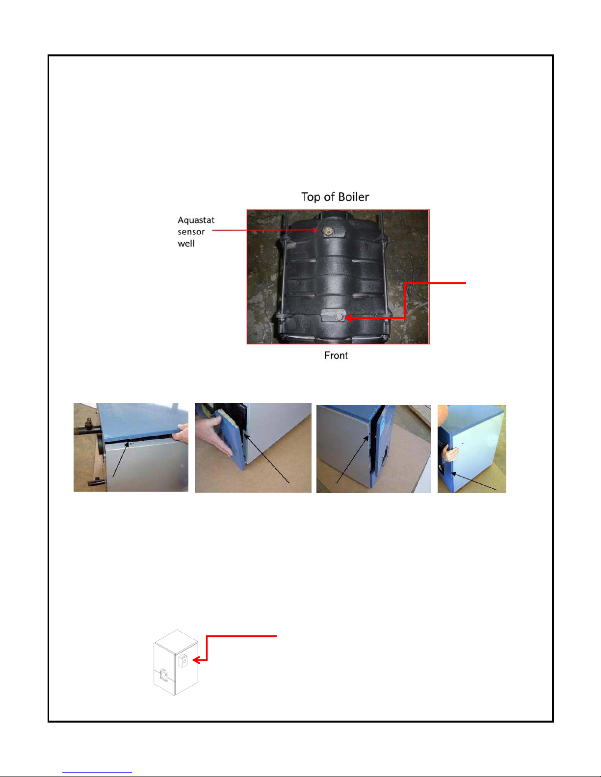
STEP 6 CONTROL SENSOR ATTACHMENT
Prior to jacket top and front panel installation the control sensor must be inserted into the brass
well located on the top of the boiler and secured by a clip. Feed the sensor through the hole
on the front of the right side panel from the outside. Penetrate the block insulation to insert the
sensor. The sensor must be fully inserted to the bottom of the well.
STEP 7 TOP AND FRONT PANEL ATTACHMENT
Affix the top panel by placing the holes located on the underside of the panel over the jacket
a
ffixing pins. Press down on the top panel and it will snap in place. Affix the lower front panel
by placing the openings on the lips of the panel over the jacket affixing screws and pushing
downward on the panel. The panel will lock in place. Repeat the process for the top front
panel.
Upon completion of the jacket assembly the Honeywell control can be mounted on the
side of the boiler. (Left or right)
Boiler control
Manual
Air Vent

9
T
he boiler is now ready for piping and connection to the fuel system, heating and
domestic hot water, thermostat and 110 Volt - 60Hz power source.
CAUTION: Safety or relief valve discharge should be piped downward to within
6” of the floor or to a drain. The valve must be mounted in a vertical position.
4.0 PIPING
Prior to connecting the B*C/G boiler to an existing piping system, certain procedures must be
f
ollowed. The system should be flushed to insure that scale and sludge will not be introduced
to the boiler. This is a must when replacing a gravity open system.
The boiler is a low mass boiler requiring low water content and steps must be taken to insure
that the boiler is not flooded from an existing high volume standing cast iron system. If the
conversion is from a high volume system a bypass loop must be installed.
Manual shut off valves must be installed on both the supply line and on the boiler bypass
loop. ASME Boiler Code requires that feed or make up water be introduced to the piping
system and not directly to the boiler. Pressure reducing valves should be installed and
adjusted to 12psi cold water. The pressure relief valve must be piped from the boiler and
downward to within 6” of the floor or to a height to meet existing code. An expansion tank,
circulating pump and automatic air eliminators must be part of the system. The relief valve,
backflow preventer and drain valve should be piped according to code to a drain with piping
that is the same size as the relief valve. The installation of the relief valve must be consistent
with ANSI/ASME Boiler and pressure vessel code Section IV or Boiler, Pressure vessel and
Pressure piping code CSA B51 as applicable.
All piping, including heating, domestic hot water and fuel lines must be done in accordance
with all local codes. It is suggested that you refer to the Water Installation Survey and
Hydronics Institute Residential Hydronic Heating Installation/Design Guide. All piping must be
properly sized, free from defect and be made of copper, steel, brass, aluminum or PEX.
Circulating Pump
A calculation for proper pump selection must be performed for all installations. The pump(s)
s
hould not be operated at maximum working pressures above 30 psi or maximum working
temperatures above 185°F and within limits advised by the manufacturer. The pump must not
be operated unless the system has been bled of all air and completely filled with water.
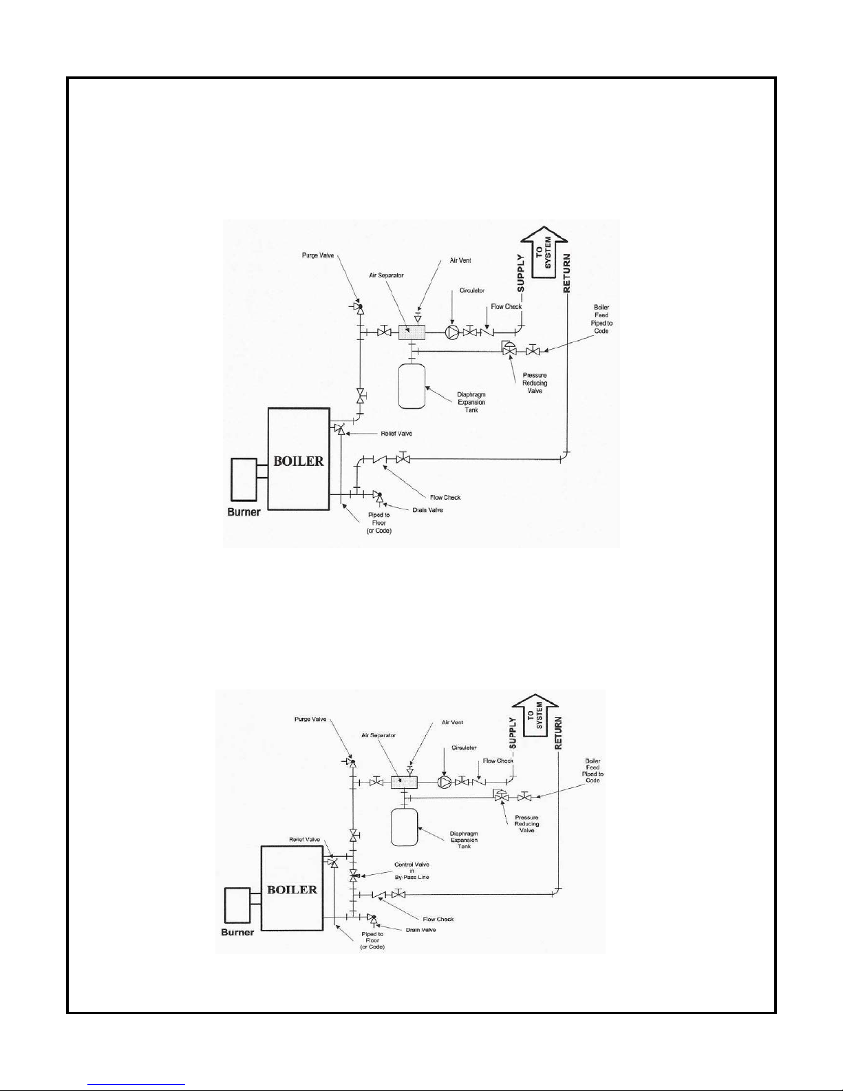
Recommended locations for the circulating pump, expansion tank, relief
valve and other trim are shown in Figure 1, Figure 2, Figure 3 and Figure 4.
10
F
igure 1
A typical installation with no domestic hot water and no by-pass loop
installed.
Figure 2
A
typical installation with no domestic hot water and with a by-pass loop
installed.
11
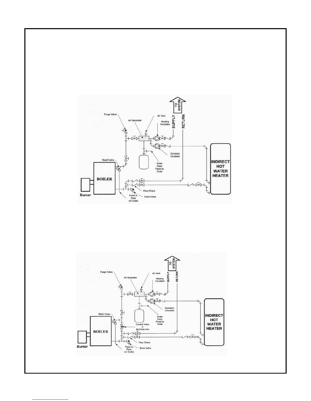
F
igure 3
A typical installation with domestic hot water supplied by an indirect heater
and with no by-pass loop installed.
Figure 4
A typical installation with domestic hot water supplied by an indirect heater
a
nd with a by-pass loop installed.
 Loading...