

Granby 115, 118, 119, 215, 218 Installation Instructions Manual
...
ECONOPLUS ELECTRIC
FURNACE
SERIES 100
Models 115, 118 & 119
SERIES 200
Models 215, 218 & 219
SERIES 300
Model 315, 318, 319 & 323
Rev : June 2009
Econoplus Series 100, 200 and 300 ELECTRIC FURNACES
INSTALLATION INSTRUCTIONS – HOMEOWNER’S MANUAL
1.0 Scope and general instructions
1.1 Installer and service technician
Use this installation guide for the initial set-up of the furnace and for subsequent service and maintenance. Keep
this document near the unit for easy reference.
1.2 Homeowner
This guide details the different modes of operation of your unit. Please read this guide after the initial
installation by your installer and keep it handy afterward for future reference.
1.3 Models covered and description
• Series 100
The 100 series is the basic electric furnace. These furnaces are factory assembled for operation with a single
stage or standard thermostat. They also have a cooling relay factory installed to enable high speed operation
when coupled with an air conditioning unit at 0.5’’W.C. (Suffix C).
Mo
del
Econoplus
KW
Total
Amps
Volts
(V/Hz/Ph)
Motor
(HP)
Motor
Speed
Static
Pressure
(‘’W.C.)
CFM ΔT
(oF)
115 15 64.4 240
/60/1
¼ -
240 Med.
0.2 925 51
115-C 15 64.8 240
/60/1
¼ -
240 High 0.5 1050 45
118 18 76.9 240/60/1
¼ -
240 Med.
0.2 925 59
118-C 18 7
7.3 240/60/1
¼ -
240 High 0.5 1050
52
119 19 78.4 240
/60/1
¼ -
240 Med.
0.2 925 63
119-C 19 78.8 240
/60/1
¼ -
240 High 0.5 1050 65
Table 1 – Series 100 characteristics
• Series 200
The 200 series is the same basic electric furnace with more functional options. These furnaces are factory
assembled for operation with a 1, 2 or 3 stages thermostat. When used with a multi-stage thermostat the
unit will modulate its power depending on the stage calling for heat. The furnace is factory assembled with a
three positions switch to manually choose the level of heat if installed with a one stage thermostat. The
intermediate modes of heating are detailed in tables 2 and 3 and explained later in this guide. The Series 200
also comes with a low speed fan switch that enables operation of the lowest speed of the motor for
continuous ventilation when needed. The Series 200 also has a cooling relay to permit high speed operation
when matched with an air conditioning unit. Suffix C indicates operation at 0.5” W.C. at high speed.
• Series 300
Series 300 has the same functionality of series 200 while being equipped with a 120V motor-blower
combination. This series also comes with, as standard equipment, a 120V terminal strip enabling connection
of additional equipment such as electronic air filter and/or humidifier. Finally, this series has insulating wool
in the blower compartment. As in series 100 and 200, suffix C indicates operation at 0.5’’ W.C. at high speed.
Series 300 features an extended capacity with the addition of a 23 KWatt model. Please note that the 23
KWatt model is ONLY offered on Series 300. Finally, Series 300 is also offered with a 1/2HP ECM motor as
optional equipment. This motor is a high efficiency (up to 80%) motor that is fully compatible with the
standard control scheme of the furnace. ECM models are identified with the ECM suffix.
Model
Econoplus
KW Total
Amps
Volts
(V/Hz/Ph)
Motor
(HP)
Motor
Speed
Static
Pressure
(“ W.C.)
CFM ΔT
(oF)
215 @ 5KW 5 22.6 240
/60/1
¼ -
240 Lo 0.2 750 21
215 @ 10KW 10 43.5 240
/60/1
¼ -
240 Lo 0.2 750 42
215 15 64.4 240
/60/1
¼ -
240 Med.
0.2 925 51
215-C 15
64.8 240
/60/1
¼ -
240 High 0.5 1050 45
218 @ 9KW
9
39.3 240/60/1
¼ -
240 Lo 0.2 750 38
218 @ 13KW
13 56
240/60/1
¼ -
240 Med.
0.2 925 44
218 18 76.9 240/60/1
¼ -
240 Med.
0.2 925 59
218-C 18 77.3 240/60/1
¼ -
240 High 0.5 1050
52
219 @ 9KW 9 39.3 240
/60/1
¼ -
240 Lo 0.2 750 38
219 @ 14KW 14 60.1 240
/60/1
¼ -
240 Med.
0.2 925 48
219 19 78.4
240
/60/1
¼ -
240 Med.
0.2 925 63
219-C 19 78.8 240
/60/1
¼ -
240 High 0.5 1050 55
Table 2 – Series 200 characteristics
Model
Econoplus
KW Total
Amps
Volts
(V/Hz/Ph)
Motor
(HP)
Motor
Speed
Static
Pressure
(“ W.C.)
CFM ΔT
(oF)
315 @ 5KW 5
25.8 240
/60/1
1/3 -
120 Lo 0.2 750 21
315 @ 10KW 10
46.7 240
/60/1
1/3 -
120 Lo 0.2 750 42
315 15
67.6 240
/60/1
1/3 -
120 Med.
0.2 1020
47
315-C 15
68.6 240
/60/1
1/3 -
120 High 0.5 1150
41
3
18 @ 9KW
9
42.5 240/60/1
1/3 -
120 Lo 0.2 750 38
3
18 @ 13KW
13
59.2 240/60/1
1/3 -
120 Med.
0.2 1020
41
318 18
77.5 240/60/1
1/3 -
120 Med.
0.2 1020
54
318-C 18
78.5 240/60/1
1/3 -
120 High 0.5 1150
48
319 @ 9KW 9
42.5 240
/60/1
1/3 -
120 Lo 0.2 750 38
319 @ 14KW 14
63.3 240
/60/1
1/3 -
120 Med.
0.2 1020
43
319 19
82.1 240
/60/1
1/3 -
120 Med.
0.2 1020
58
319-C 19
83.1 240
/60/1
1/3 -
120 High 0.5 1150
51
323 @ 10KW
10
46.7 240/60/1
1/3 -
120 Lo 0.2 750 42
323 @ 18KW
18
77.5 240/60/1
1/3 -
120 Med.
0.2 1020
54
323 23 99.0 240/60/1
1/3 -
120 M
ed. 0.2 1020
70
323-C 23 100.0
240/60/1
1/3 -
120 High 0.5 1150
62
323ECM @ 10KW
10
46.7 240/60/1
½ - 120 E
Lo
0.2 650 49
323ECM @ 18KW
18
77.5 240/60/1
½ - 120 E
Med.
0.2 1230
47
323ECM
23
96.2 240/60/1
½ - 120 E
Med.
0.2 1230
58
323ECM
-C 23
96.9 240
/60/1
½ - 120 E
High 0.5 1280
56
Table 3 – Series 300 characteristics
2.0 Important safety information
• WARNING – BASIC SAFETY WARNINGS
The initial electrical connection and subsequent service MUST be done by a qualified electrician in
accordance with this manual AND ELECTRICAL CODES HAVING JURISDICTION IN YOUR AREA.
This unit is intended and approved for use with heating ducts. Use without ducts will result in untested
operation that could result in property damage, accident or DEATH.
Disconnect power to the unit before doing any service on the unit. The type of voltage and current used in
this furnace are enough to cause serious injury and/or DEATH.
This furnace is not approved or intended for use outside. Use outside voids the warranty.
Do not store gasoline, fuel or any flammable substances near the furnace.
Ask the installer to show you the location of the main disconnect breaker of the furnace.
WARNING – BEST PRACTICES FOR OPTIMAL OPERATION
Make sure that the air filter is always clean and in good working condition and not overly obstructed. An
obstructed air filter will result in reduced air flow and higher outlet temperature. Continued operation WITH
THE FILTER CLOGGED will drastically reduce the life of the heating elements.
The unit must be inspected once a year by a qualified technician.
Make sure that you have enough clearance in the front and the rear of the unit for service and maintenance.
Although the unit is approved for zero clearance on these panels, it is definitely NOT a good practice to do it.
3.0 Installation of the furnace
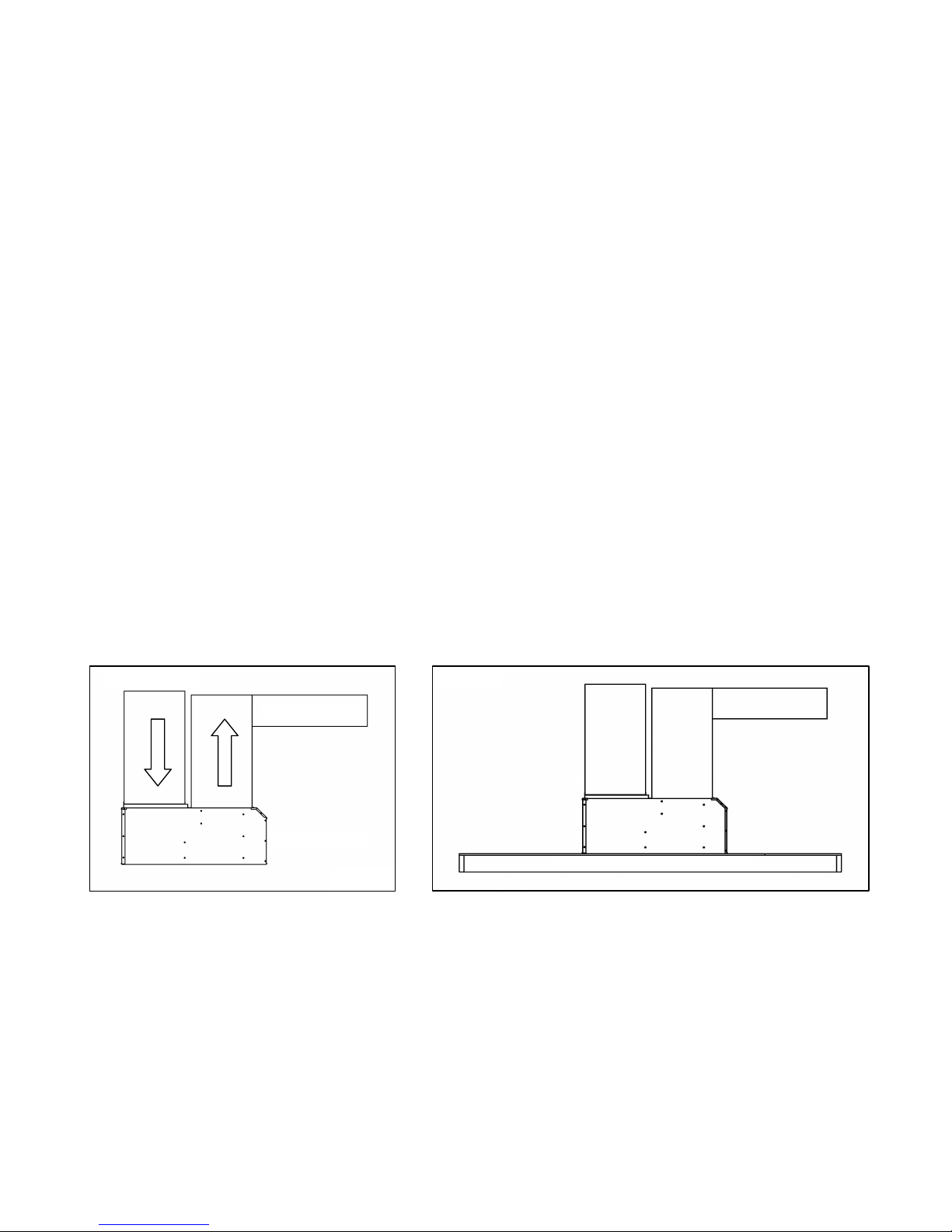
The return air/ inlet connection is made on the rear of the unit and the supply plenum is connected in the front of the
unit. The flanges supplied with the cabinet are 19” X 19” and can accommodate plenums of that size. The cabinet is also
large enough so 20” X 20” supply plenums could be attached directly on the furnace. See Figure 1 for details. The unit is
approved for installation with zero clearance on all parts of the cabinet including the floor (combustible floor) and also
with zero clearance on the walls of the supply plenum. The unit can be installed directly on the floor, on the adjustable
legs (included) or suspended to the ceiling with “plumber” straps. Please see figure 2A, 2B and 2C for the different
installation configurations. Make sure to leave sufficient clearance in the front of the unit for the electrical connections
and electrical service and in the rear of the unit for blower and motor maintenance and service. Please note that the air
filter rack can be installed on the right or left side of the unit in addition to the rear (factory position). To change the
filter rack position, refer to fig. 3.
Supply Air Plenum
Return Air Plenum
Front of furnace
Floor (Combustible floor approved)
Figure 1
Figure 2A
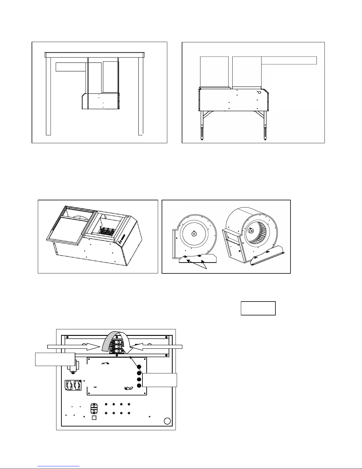
Also note that the blower in the rear compartment can be removed by loosening the 4 wing nuts (figure 3) that hold it to
the blower supports. The wire is long enough so you can remove the blower from the unit without disconnecting it.
CAUTION: when removing the blower, DO NOT remove the blower legs. Loosen the 4 wing nuts and slide the blower
out. To replace the blower, position the studs in the slots on the blower legs and fully insert the blower. Be sure to
RETIGHTEN the wings nuts after reinstalling the blower. Consult figure 4 for details.
4.0 Electrical connection to the furnace
4.1 240VAC – High voltage
You only need to bring a 2 conductors wire + ground to the furnace for the series 100 and 200 and a 3
conductors wire + ground for the series 300. The only electrical “installation” to the furnace is this connection.
All other wiring is factory installed/connected. Consult the local electrical codes for the size of the conductors
needed between the distribution panel and the furnace and
the grounding of the unit. The use of copper wires is
recommended. If aluminum wire is used, make sure to
respect all applicable codes.
Also note that it is possible to change the orientation of the
main terminal block in the furnace to accommodate a
supply wire coming from the left or right. The factory
installed position is on the right side. Knock-outs are
provided on the left and right side panels. If you choose to
reorient the main supply block, you will have to disconnect
and reconnect the internal wires to the block. To do this,
Wing Nuts
Installed with the
mounting legs supplied
as standard equipment.
See the mounting
procedure at the end of
this manual
Alternate filter rack position
Factory designed
240V connection
Alternate 240V
Wiring connection
Rotate the connection
Block for alternate
wiring direction
Figure 2B
Figure 2C
Figure 3
Figure 4
Figure 5 ( model 115 shown)
Rotation of
Supply block
 Loading...