

Granberg Kitchen Appliance Lift, 870-04063, 870-05063, 870-06063 Instruction Manual
Granberg Interior AB
Box 6112
SE-600 06 Norrköping
SWEDEN
Tel: +46 (0)11-19 77 50
Kitchen Appliance Lift
INSTRUCTION MANUAL
www.AccessibilityPro.com 1-877-947-7769

Section: Headline: Page:
1. Introduction ........................................................................................................................................................4
2. Declaration of Conformity
...........................................................................................................................
4
3. Intended use - Technical data ......................................................................................................................4
Installation instructions:
4.1 Mechanical construction ................................................................................................................................5
4.2 Delivery modules
................................................................................................................................................
5
4.3 Location of electric connections .................................................................................................................5
4.4 Installation in the cabinet
...................................................................................................................................
6
4.5 Location of push button unit ........................................................................................................................6
4.6 Functional test
.................................................................................................................................................7
Operator’s information:
5.1 Safe use .................................................................................................................................................................7
5.2 Load distribution and side forces
...............................................................................................................8
5.3 Actions after use
.................................................................................................................................................
8
5.4 Control device options ....................................................................................................................................9
5.5 Cleaning
...........................................................................................................................................................
10
5.6 Maintenance
...................................................................................................................................................
10
6. Instructions for Recycling
.............................................................................................................................
11
7. Decals
..................................................................................................................................................................
11
8. Warranty
.............................................................................................................................................................
12
9. Service & maintenance records
.................................................................................................................
13
10. Fault-finding .................................................................................................................................................... 14
11. Spare parts list ................................................................................................................................................. 14
12. Electric circuit diagram
..................................................................................................................................
15
13. CE-declaration of Conformity
......................................................................................................................
15
Contents
4
3. Intended use - Technical data
The Kitchen appliance lift 870 is intended to achieve a convenient location for handling material, which has been placed on the
Lift platform by means of manoeuvring it along an arc-shaped path up to top level, or to bring it into the cabinet. The operation
shall be indoors, under normal housing conditions regarding temperature, humidity and lighting. The Kitchen appliance lift is not
intended for use in moist environments. It is assumed that the cabinet is made according the standards EN 1116 and EN 1153.
Model: 870-04063 870-05063 870-06063
Cabinet width 400 mm 500 mm 600 mm
Cabinet height, inside Adjusted for the height of the
load on the platform.
Adjusted for the height of the load on
the platform.
Adjusted for the height of the load
on the platform.
Cabinet depth, inside Adjusted for the size of the load
on the platform.
Adjusted for the size of the load on
the platform.
Adjusted for the size of the load on
the platform.
Vertical stroke, max 575 mm 575 mm 575 mm
Horizontal stroke, max 500 mm 500 mm 500 mm
Machine depth, raised platform 1055 mm 1055 mm 1055 mm
Machine depth, lowered platform 555 mm 555 mm 555 mm
Machine height, raised platform 745 mm 745 mm 745 mm
Machine height, lowered platform 660 mm 660 mm 660 mm
Platform width 330 mm 430 mm 530 mm
Platform length 350 mm 350 mm 350 mm
Time for a lift or lowering stroke,
approx
16 sec. 16 sec. 16 sec.
Mains supply 230V / 120V* 230V / 120V* 230V / 120V*
El. protection class IP 54 IP 54 IP 54
Power consumption 120V / 230V 324 W / 345 W 324 W / 345 W 324 W / 345 W
Max no. of full work cycles per hour 6 6 6
Control voltage 24 V DC 24 V DC 24 V DC
Weight 15 kg 15 kg 15 kg
Max load on the platform 20 kg 20 kg 20 kg
The noise pressure is less than 70 db(A) 70 db(A) 70 db(A)
Technical data, Kitchen appliance lift 870:
1. Introduction
We have the pleasure to deliver a Granberg Interior Kitchen appliance lift 870, an electrically operated lifting and lowering
system for e.g. food processing machines, bottle crates, microwave oven, computer, sewing-machine etc.
The Lift includes a wooden board platform, onto which the load shall be placed. With the push button box the motorized
platform with its load is brought to convenient reach height.
Only authorized persons may use the Kitchen appliance lift!
Authorization means obligation to read and follow the instructions.
It is very important that you read and understands the instructions before you use the device.
If you have any questions - contact your supplier.
This Instruction manual shall be available for all concerned persons, be kept in a protected place and shall follow the product,
if it is moved to another installation site or another house or apartment owner.
Correct use, operation, inspections and maintenance are
decisive for efficient and safe work.
2. Declaration of Conformity with EU-directives
This product is CE-marked and is granted to conform to the basic safety and operation requirements, in accordance with the
actual Machinery, EMC- and Low voltage Directives. A separate ”CE-Declaration of Conformity” is available in section 13.
* The voltage depends on which model that is delivered
5
G
A
B
C
D
E
F
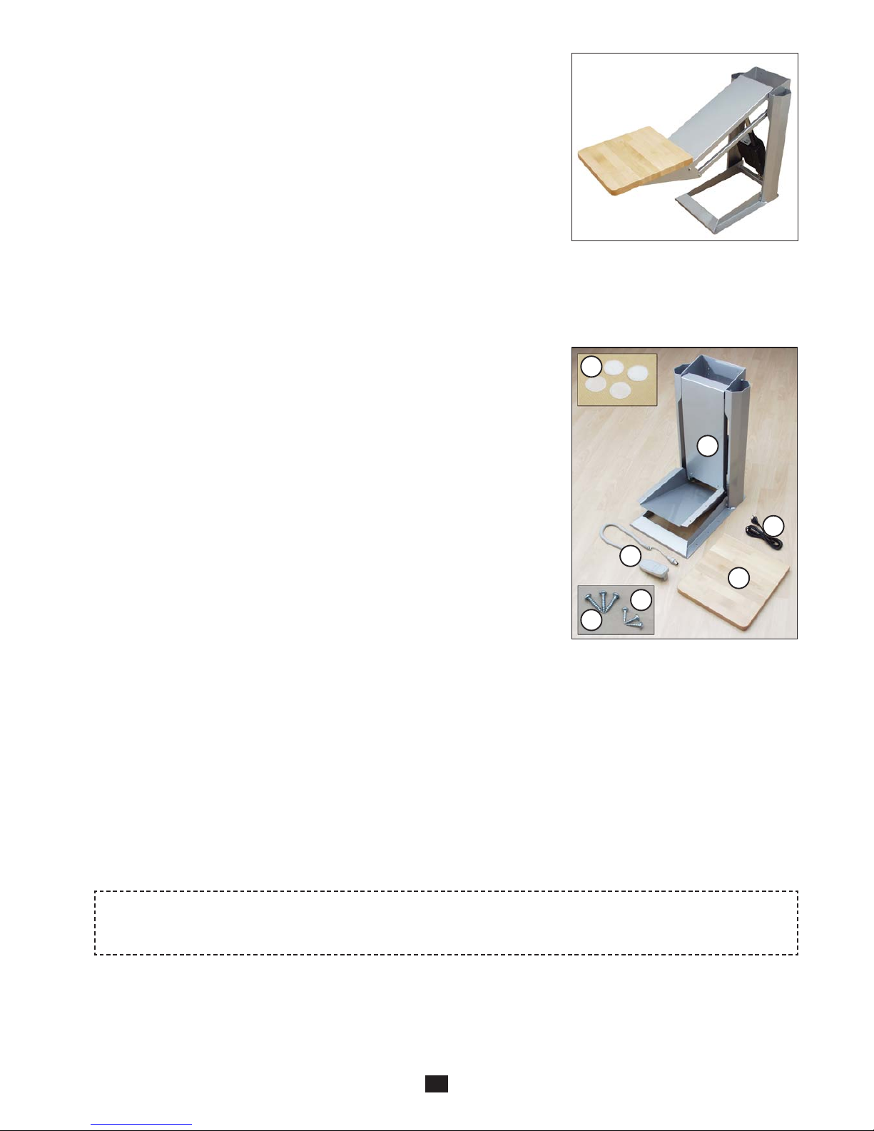
4.2 Delivery modules
The Kitchen appliance lift is delivered in a box. The parts acc. picture 2 shall be
installed acc. to the installation instruction. See section 4.4.
The packaging material shall be handed over to an organized material re-cycling
organisation.
A - Lift mechanism
B - Mains cable to the power unit
C - Wooden platform
D - 10 off 6x30 mm wood screw, for mounting the lift mechanism in the cabinet
E - 6 off 4x20 mm wood screw, for mounting the platform on the lift mechanism
F - Hand-held control unit
G - Self-adhesive Velcro pads
4.1 Mechanical construction
The Kitchen appliance lift 870 comprises a motor powered parallel-acting
arm system that lifts and lowers the platform. The lifting arrangement is fixed
onto a framework. The curved lifting and lowering motion is achieved by an
electrically powered screw jack, which is attached in the framework and in
the arm system.
Picture 1
Picture 2
4.3 Location of the electric connection
The Kitchen appliance lift must be connected to a separate mains switch, which is placed in the vicinity of the lift.
A double electric socket 230 V or 120 V (The voltage depends on which model that is delivered) shall be installed in the
cabinet. (Also an electrically operated device, which is placed on the platform, is fed from the same socket).
Place the socket so that it does not disturb the motion of the Kitchen appliance lift.
Be careful with the location and fastening of the cables, so that they cannot be damaged.
* Power consumption 230 V = 575 W
* Power consumption 120 V = 720 W
An authorized electrician must make the electric installation!
6
C
B
A
A
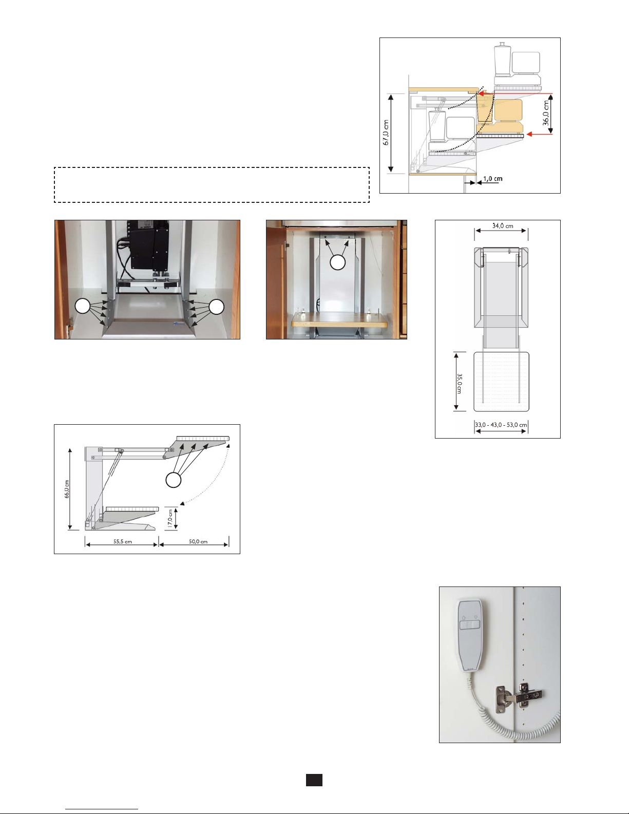
4.4 Installation in a cabinet
To consider before installation:
The dimensions of the cabinet must be suitable for the size of the Kitchen appliance lift as well as for the space required for the load. A standard cabinet with
inside height 67 cm and depth minimum 56 cm is sufficient. The location of the lift
is adapted for the size of the cabinet, to the size of the load and to desired height
in the raised position. Be aware of that the maximum height of the load at the rear
end of the platform is 36 cm when the Kitchen appliance lift is installed 1 cm from
the cabinet front edge, for the standard cabinet described above. Other cabinet
dimensions or other load location can allow higher or lower load.
4.5 Location of the control box
A hand-held control box is delivered as standard, and this shall be placed in the cabinet or
on the inside of the cabinet door. Thereby it is prevented that the Kitchen appliance lift is
operated before the door has been opened.
There are two alternatives for parking the push button box:
Suspension hook:
When delivered the push button box is provided with a suspension hook.
Self-adhesive Velcro pads:
Dismantle the hook from the push button box and put the included self-adhesive pads on
the backside of the control unit.
Check the position of the cable carefully, so that it cannot be jammed.
Picture 2
4.4.1
Put the Kitchen appliance lift on the bottom
of the cabinet, approx. 1 cm from the front
edge of the cabinet. Fix screws in all 8 holes of
the bottom frame (A).
4.4.2
Fix the upper part of the Kitchen
appliance lift to the wall (B). Fill the
space between the
Kitchen appliance lift and the wall
with a suitable wooden joist.
4.4.3
Connect to the electric socket
and operate the lift to the top
position.
Fix the platform onto the lift
rack with six wood screws (C),
picture 1. (The platform has
got markings for the location
of the screws).
Side view
From above
Picture 1
Competent persons must make the installation work!
 Loading...