

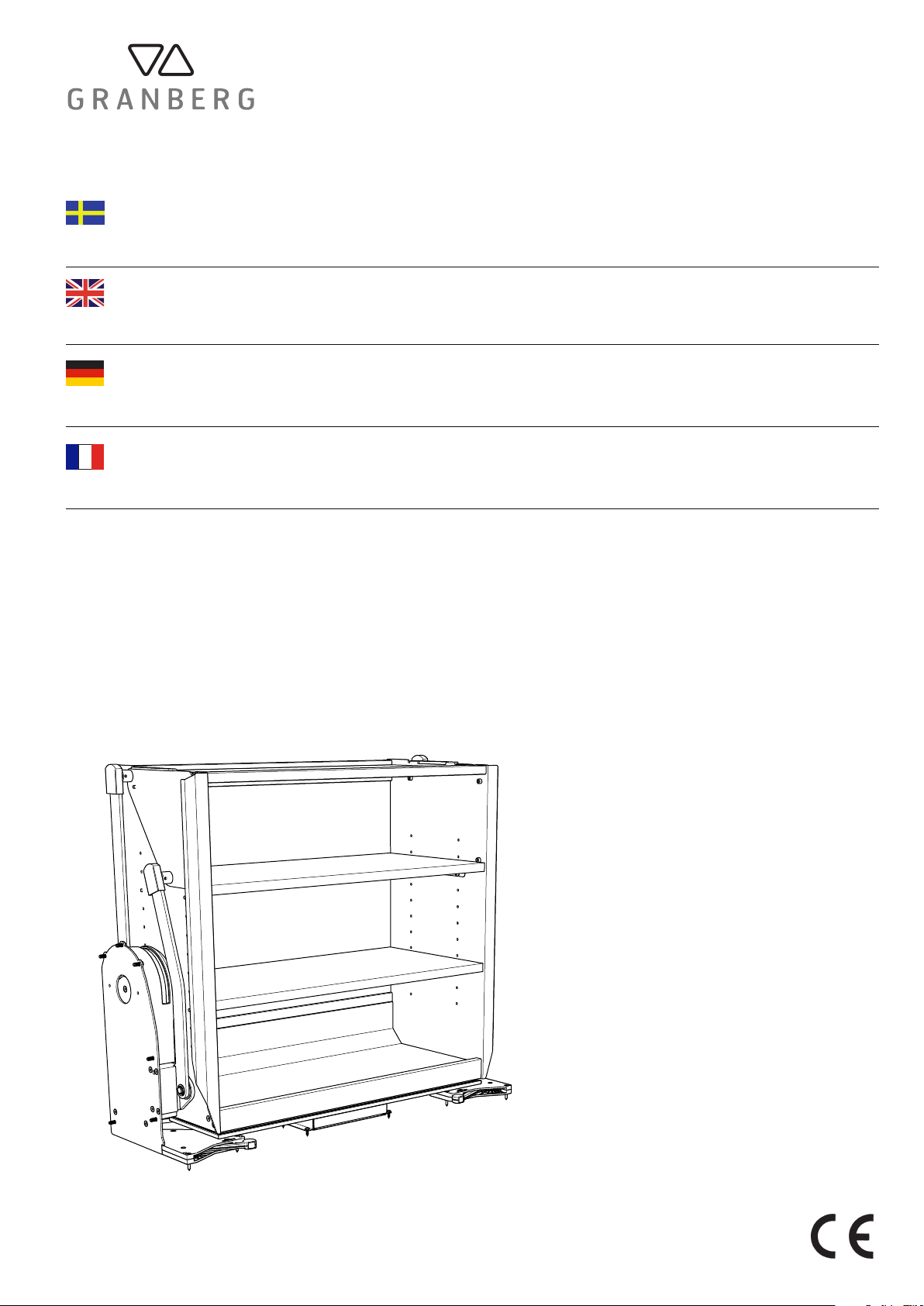
Granberg InDIago 510 Installation Instructions Manual
Installationsanvisning
InDiago 510
Installation Instructions
InDiago 510
Montageanleitung
InDiago 510
Notice de montage
InDiago 510
Dok. Nr: M510
V: 1.1
2018-03-19

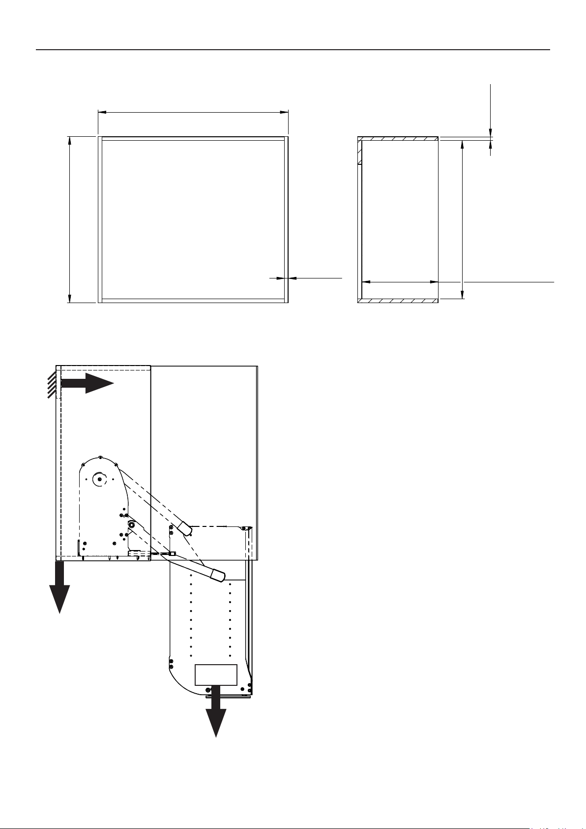
Teknisk data / Technical data / Technische Daten / Données techniques
Min 460
Max 968
318 / 418 / 518 / 618 / 718 / 818
650 / 800
(mm)
254 / 304
kg
614
248 / 298
InDIago 510
230/50Hz/2.0A
20 mm / s
470 mm
40 kg
6 / 1h
Planering / Planning / Planung / Planification
16 - 20
500 / 600 / 700 / 800 / 900 / 1000
(mm)
min 700 / min 850
600N
16 - 20
min 660 / min 810
min 260 / min 310
900N
750N
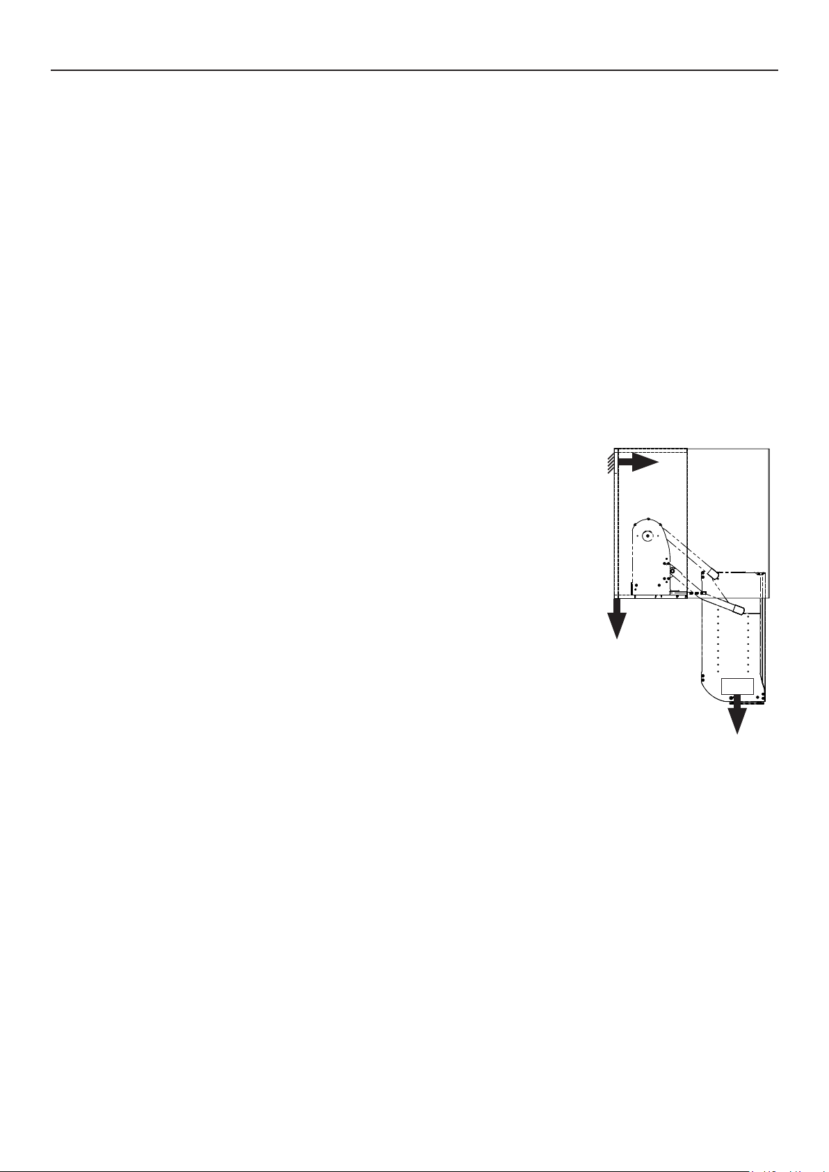
Planering / Planning / Planung / Planification
Mycket Viktigt!
SE
Kontrollera skåpets fastsättning i vägg före installation!
Vid max belastning och fullt utkörd kan dragkraften i vägg uppgå till 600N
Säkerställ att skruvförband och skick på skåp uppfyller dessa krav.
Kontrollera skicket på spikregelns sammanfogning med skåpsidor.
Förstärk med en byggvinklar fastsatta i skåpets sidor och in i vägg genom spikregel för att få en starkare
fastsättning i vägg.
Sammanfoga även skåpet med skåp vid sidorna för att fördela ut kraften ytterligare.
Gångjärn
Alla skåpstillverkare har olika typer av gångjärn och placering.
Vi har utfromat produkten för att fungera med så många typer och gångjärn och dess placering som är möjligt.
Det kan ändock förekomma fall där gångjärnen är i konikt med produkten.
Gångjärnen yttas då för att inte kollidera med produkten eller dess rörliga delar.
Dämpning som är monterade utanpå gångjärn avlägsnas.
Gångjärn med integrerad dämpning är kompatibla.
600N
Very important!
EN
900N
Check the cabinet xing on the wall before installation!
At maximum load and fully driven, the tensile force in the wall can reach 600N.
Make sure that the screw connection and condition of the cabinet meet these requirements.
Check the condition of the wall joining with cupboard sides.
Reinforce with an angle bracket xed in the sides of the cabinet and into the wall through the cabinet to get a stronger
wall xing.
Also connect the cabinet with cabinets at the sides to further distribute of the forces.
750N
Hinges
All cabinet manufacturers have dierent types of hinges and placement.
We have developed the product to work with as many types and hinges and its location as possible.
There may even be cases where the hinges are in conict with the product.
The hinges must then be moved so as not to collide with the product or its moving parts.
Dampings mounted outside of the hinges must be removed.
Hinges with integrated damping are compatible.
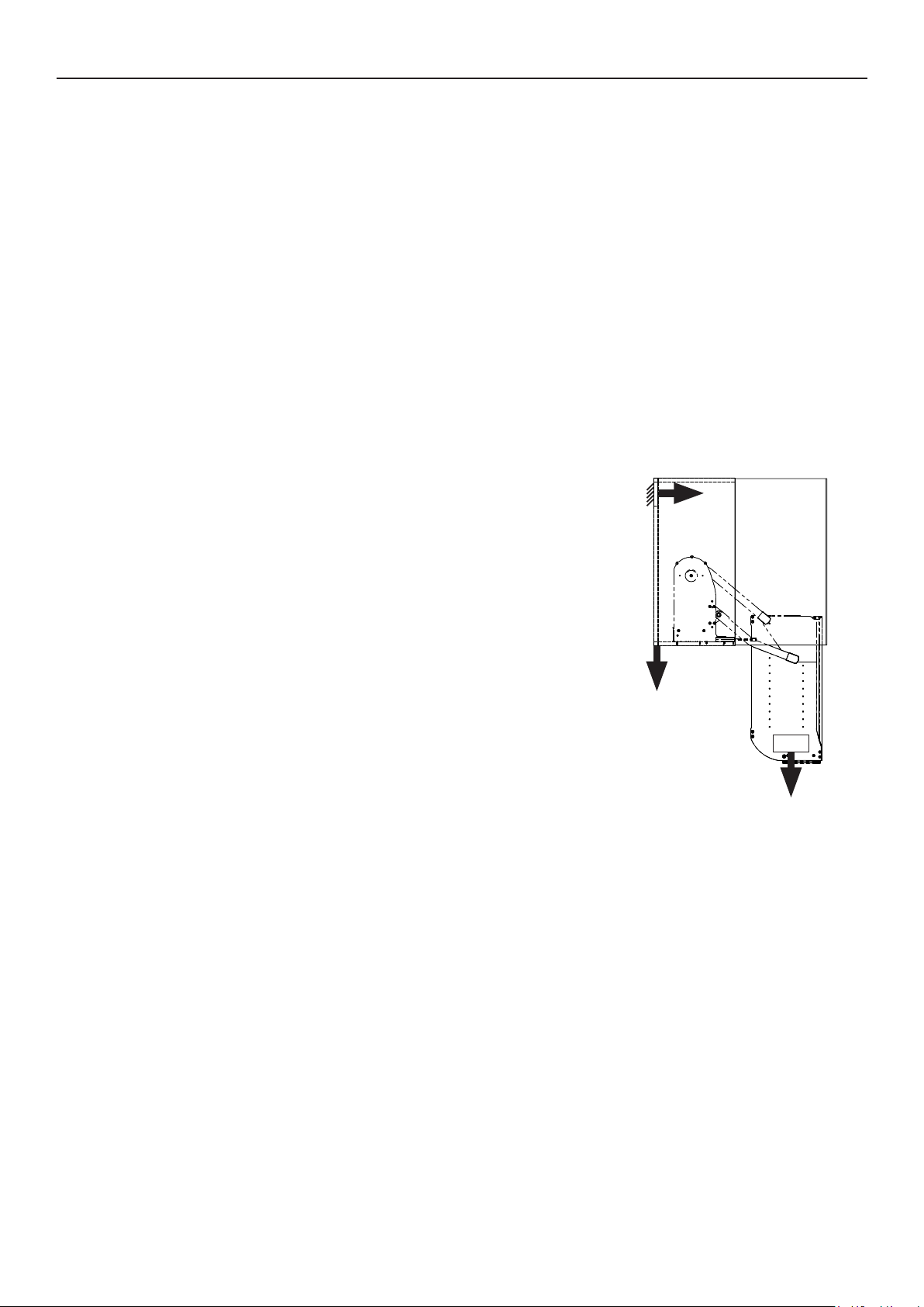
Planering / Planning / Planung / Planification
Sehr wichtig!
DE
Überprüfen Sie vor der Montage die Wandbeschaenheit!
Bei max. Belastung können während des Betriebs Zugkräfte von bis zu 600N an der Wand auftreten.
Stellen Sie sicher, das die Schrankaufhängung dieser Belastung standhält.
Gegebenenfalls müssen weiter Befestigungspunkte gesetzt werden.
Um eine möglichst große Stabilität zu erhalten, verschrauben Sie den Schrankkorpus mit den seitlich anschließenden
Schränken (falls vorhanden).
Scharniere
Je nach Möbelhersteller variieren die Montagemaße und die Art der Scharniere.
Wir haben unser Produkt so konstruiert, das es mit den gängigsten Fabrikaten kompatibel ist.
Sollte es dennoch zu Problemen kommen, so müssen die Scharniere versetzt werden, damit eine einwandfreie Funktion
gewährleistet wird.
Aufgesetzte Scharnierdämpfungen müssen entfernt werden.
Scharnieren mit integrierter Dämpfung sind kompatibel.
900N
600N
Très important!
FR
Vériez la xation du caisson sur le mur avant l’installation!
Une fois le caisson chargé et en fonctionnement, la force de traction sur le mur peut atteindre jusqu’à 600N
Assurez-vous que le support murale et la suspension du caisson peuvent supporter cette charge.
Si nécessaire, d’autres points de xation doivent être dénis.
An d’obtenir la plus grande stabilité possible, renforcer avec une equerre xée dans les coins du caisson et dans le mur
pour obtenir pour obtenir une plus forte xation murale (si possible).
Connectez également l’armoire avec des armoires sur les côtés pour répartir davantage la puissance.
Charnière
Selon le fabricant de meubles, les dimensions de montage et le type de charnières varient.
Nous avons conçu notre produit pour être compatible avec les marques les plus courantes.
Si toutefois il y a des problèmes, les charnières doivent être déplacées, de sorte qu’une fonction parfaite
est garanti.
Les ”amortisseurs” de charnière attachés doivent être enlevés.
Tracer des repères de perçage sur les côtés du caisson.
750N
Elektricitet / Electricity / Strom / Électricité
500 / 600 / 700 / 800 / 900 / 1000
min 260 / min 310
min 660 / min 810
16 - 20
16 - 20
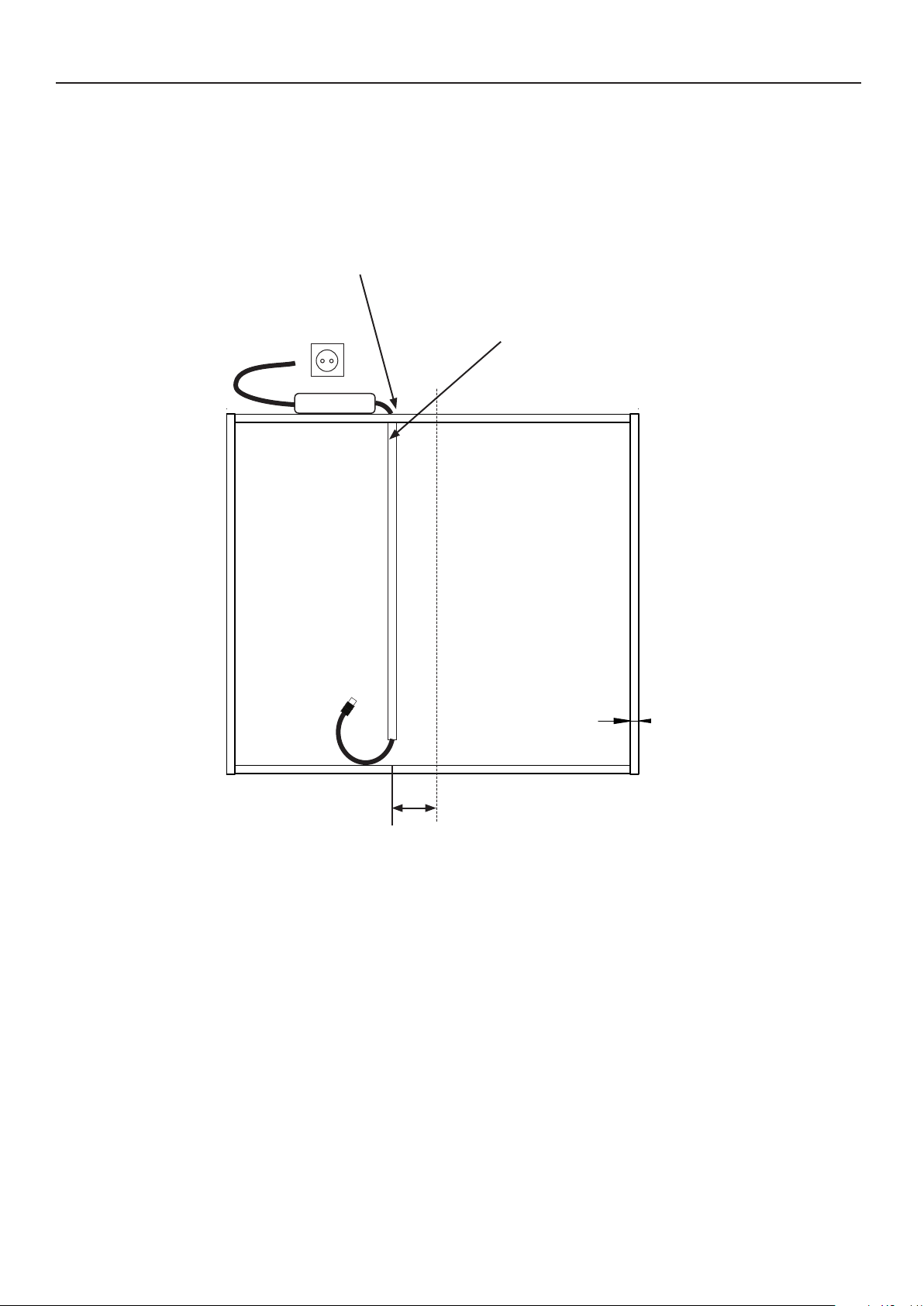
Borra ett 30mm hål i skåpstakets bakkant.
Drill a 30mm hole in the back of the cabinet.
Bohren Sie ein 30 mm Loch an der Hinterkante des Schranks.
Percez un trou de 30 mm à l’arrière de l’armoire.
230V
TRAFO
(mm)
Kabelkanal, max djup 10mm
Cable channel, max depth 10mm
Kabelkanal, maximale Tiefe 10mm
Canal de câble, profondeur maximale 10mm
centrum
90 mm
1
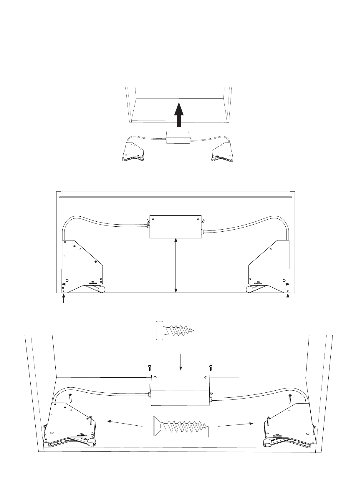
Placera lucköppnarenheten på botten av skåpet och skruva fast.
Place the door opener on the bottom of the cabinet and screw it tight.
Platzieren Sie den Türöner wie unten gezeigt auf dem Unterboden des Schranks.
Placez l’ouvre-porte sur le fond de l’armoire et vissez-le fermement.
185 mm
2x - 4x12mm
6x - 3,5 x 25 mm
 Loading...