

Grams Medical Aspirator S-300 Operating & Maintenance Instructions
Grams
Medical
Operatinu & Maintenance Instructions
For Grams Aspirator
Turnina The Aspirator On
The center position of the switch on the electrical panel is OFF. Placing switch in the UP position
bypasses the foot pedal and turns the aspirator on manually. To use the Pneumatic foot pedal, place the
switch in the DOWN position. The foot pedal is a "Push On
*
For best results using the foot pedal, press quickly and firmly.
*
The pilot light is illuminated when the aspirator is on.
"
In the event of electrical overload there is a circuit breaker on the electrical panel that
can be manually reset.
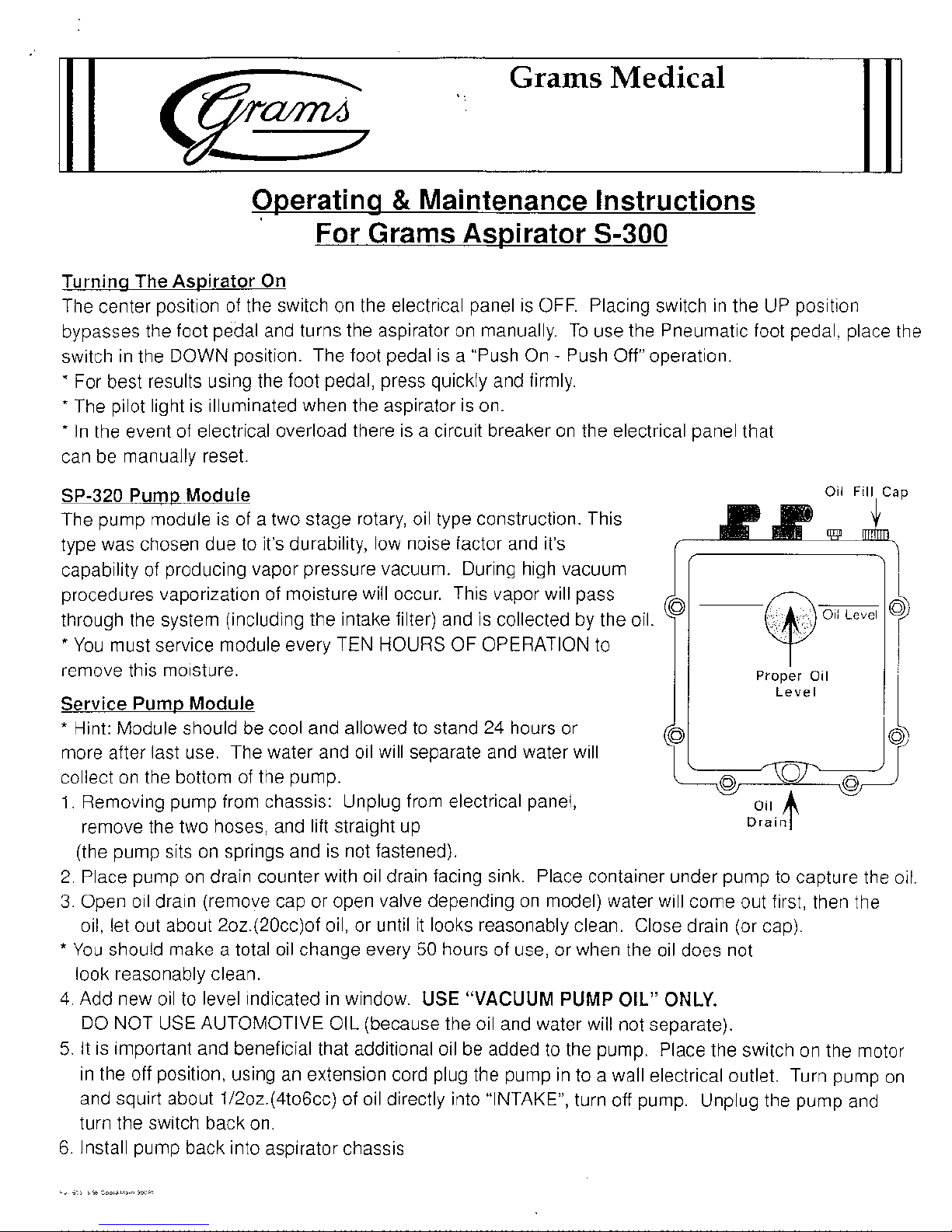
SP-320 Pump Module
The pump module is of a two stage rotary, oil type construction. This
type was chosen due to it's durability, low noise factor and it's
capability of producing vapor pressure vacuum. During high vacuum
procedures vaporization of moisture will occur. This vapor will pass
through the system (including the intake filter) and is collected by the oil.
*
You must service module every TEN HOURS OF OPERATION to
remove this moisture.
Service Pump Module
*
Hint: Module should be cool and allowed to stand 24 hours or
more after last use. The water and oil will separate and water will
collect on the bottom of the pump.
1.
Removing pump from chassis: Unplug from electrical panel,
remove the two hoses, and lift straight up
(the pump sits on springs and is not fastened).
2.
Place pump on drain counter with oil drain facing sink. Place container under pump to capture the
3.
Open
011,
*
You should make a total oil change every 50 hours of use, or when the oil does not
look reasonably clean.
4.
Add new oil to level indicated in window.
DO
5.
It is important and beneficial that additional oil be added to the pump. Place the switch on the motor
in the off position, using an extension cord plug the pump in to a wall electrical outlet. Turn pump on
and squirt about
turn the switch back on.
6.
Install pump back into aspirator chassis
011
drain (remove cap or open valve depending on model) water will come out f~rst, then the
let out about 2oz.(20cc)of oil, or until it looks reasonably clean. Close drain (or cap).
USE "VACUUM PUMP OIL" ONLY.
NOT USE AUTOMOTIVE OIL (because the oil and water will not separate).
1/2oz.(4to6cc) of oil directly into "INTAKE", turn off pump. Unplug the pump and
S-300
-
Push Off" operation.
1-JI
Level
oil
+
Drain
011
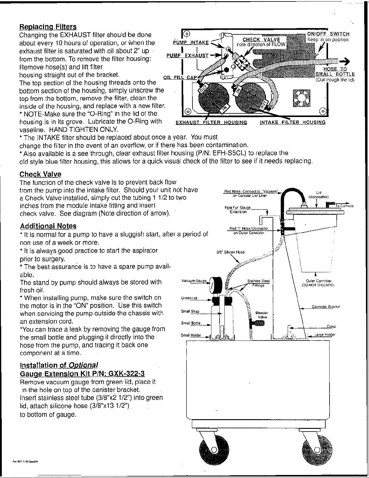
Replacina Filters
Changing the EXHAUST filter should be done
about every
10
hours of operation, or when the
exhaust filter is saturated with oil about
2"
up
from the bottom. To remove the filter housing:
Remove
hose(s) and lift filter
housing-straight out of the bracket.
The top section of the housing threads onto the
bottom section of the housing, simply unscrew the
top from the bottom, remove the filter, clean the
inside of the housing, and replace with a new filter.
*
NOTE-Make sure the "0-Ring" in the lid of the
housing is in its grove. Lubricate the 0-Ring with
EXHAUST
FILTER
HOUSING INTAKE
FILTER
HOUSING
vaseline. HAND TIGHTEN ONLY.
*
The INTAKE filter should be replaced about once a year. You must
change the filter in the event of an overflow, or
if
there has been contamination.
*Also available is a see through, clear exhaust filter housing (PIN:
EFH-S5CL) to replace the
old style blue filter housing, this allows for a quick visual check of the filter to see if it needs replacing.
Check Valve
The function of the check valve is to prevent back flow
from the pump into the intake filter. Should your unit not'have
a Check Valveinstalled, simply cut the tubing 1 112 to two
inches from the module intake fitting and insert
!la
check valve. See diagram (Note direction of arrow).
Additional Notes
*
It is normal for a pump to have a sluggish start, after a period of
non use of a week or more.
*
It is always good practice to start the aspirator
prior to surgery.
*
The best assurance is to have a spare pump avail-
able.
The stand by pump should always be stored with
(DO
NOT
DISCARD)
fresh oil.
*
When installing pump, make sure the switch on
the motor is in the "ON" position. Use this switch
when servicing the pump outside the chassis with
an extension cord.
*You can trace a leak by removing the gauge from
the small bottle and plugging it directly into the
hose from the pump, and tracing it back one
component at a time.
Installation of
O~tional
Gauae Extension Kit
PIN:
GXK-322-3
Remove vacuum gauge from green lid, place it
in the hole on top of the canister bracket.
Insert stainless steel tube
(3/8"x2 112") into green
lid, attach silicone hose
(31811x1 3
112")
to bottom of gauge.
J
S-300
Assembly Instructions
Unpacking
Unpack all three boxes.
wrapping and packing. Discard packing, except the pump
box (box
pump. You might need this later to
service.
"20f3") its foam and two little red vinyl caps from the
Remove everything out of its
send.the pump in for
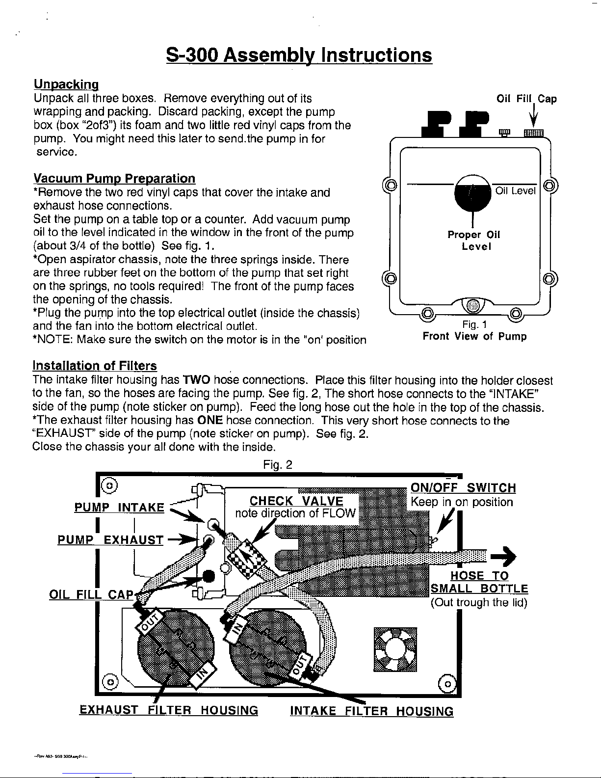
Vacuum Pump Preparation
*Remove the two red vinyl caps that cover the intake and
exhaust hose connections.
Set the pump on a table top or a counter. Add vacuum pump
oil to the level indicated in the window in the front of the pump
(about 314 of the bottle) See fig.
*Open aspirator chassis, note the three springs inside. There
are three rubber feet on the bottom of the pump that set right
on the springs, no tools required! The front of the pump faces
the opening of the chassis.
*Plug the pump into the top electrical outlet (inside the chassis)
and the fan into the bottom electrical outlet.
*NOTE: Make sure the switch on the motor is in the "on' position
1.
@
Front
Proper
Level
View
Oil Level
Oil
of Pump
Installation of Filters
The intake filter housing has
to the fan, so the hoses are facing the pump. See fig. 2, The short hose connects to the "INTAKE"
side of the pump (note sticker on pump). Feed the long hose out the hole in the top of the chassis.
*The exhaust filter housing has
"EXHAUST" side of the pump (note sticker on pump). See fig. 2.
Close the chassis your all done with the inside.
TWO
ONE
hose connections. Place this filter housing into the holder closest
hose connection. This very short hose connects to the
Fia. 2
EXHAUST FILTER HOUSING INTAKE
FILTER
HOUSING

Installation of Canister Bracket & Vacuum Jar
Place the canister bracket in the large holder on top of the chassis, so the loop faces the end
of the chassis with the electrical panel, then snap the clasps into place.
*Place green lid on top of small bottle, set the jar in the small holder, so that the two stainless
steel hose connections face towards the canister bracket. Use the 'small' strap to fasten the
jar to the chassis.
*Connect the vacuum hose sticking out of the lid
(from the inside) to the bleeder
hose connection that is attached to the small
bottle).
*Insert vacuum gauge into green lid.
valve (a black plastic
*Place
318"~ 12" silicon hose onto the red plastic
hose tee on the outer canister. Set the outer
canister in the loop so the hose faces the
bracket, then thread the hose through the slot
in the bracket and attach to strait stainless
steel fitting in small jar. For complete
&
instructions on the disposable lids
liners
(CL-340) see separate instructions in the lids
&
liners box.
Installation of Foot Pedal
Push hose (from foot pedal) onto tube on
the electrical panel marked
"pneumatic foot pedal".
(if it does not fit snugly trim about 1" off the
hose) That's it your done!
Installation of
Gauae Extension Kit
Remove vacuum gauge from green lid, place it
in the hole on top of the canister bracket.
Insert stainless steel tube (318x2
silicone hose attached into green lid, attach
silicone hose
gauge.
Optional
PIN:
GXK-322-3
112") with
(3/8"x13 112") to bottom of
P/ease don Y hesitate to ca// the factoy forpersona//hsfruction
Grams
design and production of medical instrumentation
Medical
- - - - -
-
-
-
-
 Loading...