

Grainger LumaPro 436R33, LumaPro 446M57, LumaPro 446M61, LumaPro 446M58 Operating Instructions Manual
Please read and save these instructions. Read through this owner’s manual carefully before
using product. Protect yourself and others by observing all safety information, warnings, and
cautions. Failure to comply with instructions could result in personal injury and/or damage to
product or property. Please retain instructions for future reference.
Operating Instructions 436R33, 446M61, 446M57, 446M58
LED Area Light
Fixtures
Description
These Area Light fixtures deliver class-leading efficacy in a lightweight design that can be
effortlessly applied to new and retrofit outdoor projects.
Picture is for illustration purposes only.
Your model may vary.
FEATURES
• Universal 120-277V dimming driver standard
• Greater than 100,000 hour L70 lifetime at TM21 standards at 25°C
Specifications and Dimensions
436R33 120-277V 60W 5000K 7,990 75 Type IV 3.22” x 12.28” x 22.48”
446M61 120-277V 60W 5000K 7,990 75 Type V 3.22” x 12.28” x 22.48”
446M57 120-277V 100W 5000K 12,540 75 Type V 3.22” x 12.28” x 22.48”
446M58 120-277V 100W 5000K 12,540 75 Type V 3.22” x 12.28” x 22.48”
Dimensions (in)
Model Volts Watts CCT Lumens CRI Type H” x W” x D”

2
LumaPro Operating Instructions
436R33, 446M61, 446M57, 446M58
LED Area Light
Fixtures
General Safety Information
• To reduce the risk of death, personal injury or property damage from fire, electric shock,
falling parts, cuts/abrasions, and other hazards read all warnings and instructions
included with and on the fixture box and all fixture labels.
• Before installing, servicing, or performing routine maintenance upon this equipment,
follow these general precautions.
• Commercial installation, service and maintenance of luminaires should be performed by
a qualified licensed electrician.
• DO NOT INSTALL DAMAGED PRODUCT!
• This fixture is intended to be connected to a properly installed and grounded UL
listed junction box.
WARNING:
RISK OF ELECTRICALSHOCK
• Turn off electrical power at fuse or circuit breaker box before wiring fixture to the
power supply.
• Turn off the power when you perform any maintenance.
• Verify that supply voltage is correct by comparing it with the luminaire label information.
• Make all electrical and grounded connections in accordance with the National Electrical
Code and any applicable local code requirements.
• All wiring connections should be capped with UL approved wire connectors.
CAUTION:
RISK OF INJURY
• Unit will fall if not installed properly. Follow installation instructions.
• Wear gloves and safety glasses at all times when removing luminaire from carton,
installing, servicing or performing maintenance.
• Avoid direct eye exposure to the light source while it is on.
• Account for small parts and destroy packing material, as these may be hazardous
to children.
CAUTION:
RISK OF FIRE
• Keep combustible and other materials that can burn away from luminaire and lamp/lens.
• MIN 90°C SUPPLY CONDUCTORS.
3
LumaPro Operating Instructions
436R33, 446M61, 446M57, 446M58
LED Area Light
Fixtures
Installation & Operation
Disconnect the power by turning off the circuit breaker or by removing the
appropriate fuse at the fuse box. Turning the power off using the light switch is not
sufficient to prevent electrical shock.
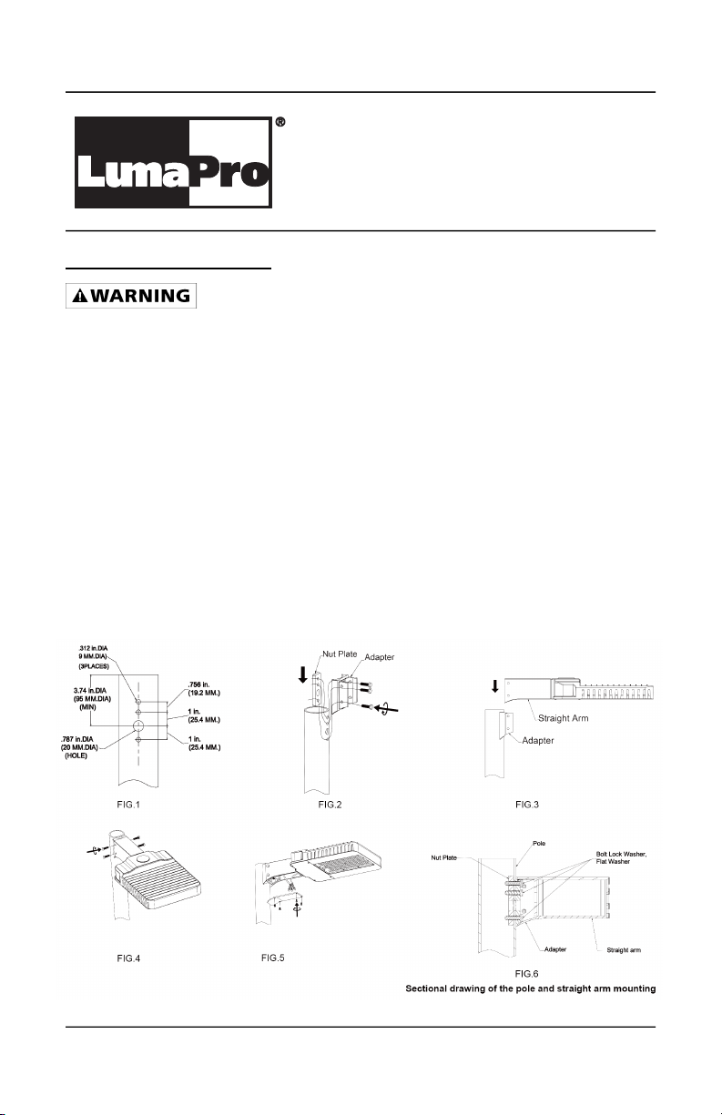
Straight Arm Pole Mounting:
This fixture can be configured to pole and an adapter plate has been included to mount to
the pole. Hole pattern on the pole shall be in accordance with FIG.1. If there is no hole on
the pole, drill holes according to the pattern in FIG.1.
Different adapters are optional, including square pole adapter, 3” round pole adapter
(RPA), 4”RPA, and 5”RPA.
• Tighten the nut plate and adapter on the pole (see FIG.2).
• Insert the fixture into the adapter (see FIG.3).
• Tighten the four M8 screws on the straight arm and secure it to the adapter (see FIG.4).
• Connect the power lead properly, make wirings inside the straight arm, and tighten
the arm door with screws (see FIG.5).
• Inspect installation to ensure fixture is secure.

4
LumaPro Operating Instructions
436R33, 446M61, 446M57, 446M58
LED Area Light
Fixtures
Straight Arm Pole Drill Pattern
5
LumaPro Operating Instructions
436R33, 446M61, 446M57, 446M58
LED Area Light
Fixtures
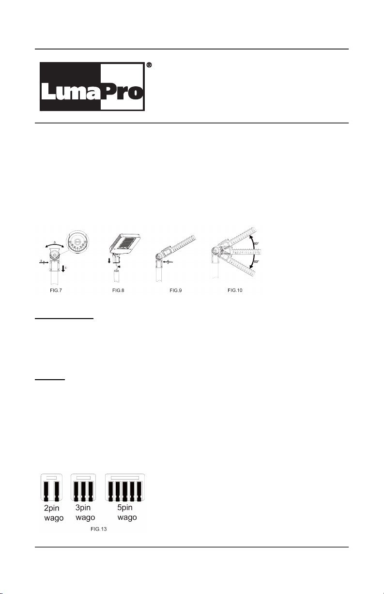
Straight Arm Pole Mounting:
This fixture can be configured to provide 0 to 60° both upward and downward aiming in 15°
increments (see FIG.7).
• Connect the power lead properly, Make wiring connection (see WIRING) and lay the
wires in the pole, insert the Slipfitter to the pole(see FIG.8).
• Tighten the four M8 bolts on the slipfitter and secure it to the pole (see FIG.9).
• To aim the fixture, loosen and adjust the M12 knuckle bolt to right angle, adjust the aim
0 to 60°both upward and downward (see FIG.10).
• Inspect installation to ensure fixture is secure.
Maintenance
The unit is designed for years with minimum care. For optimum performance, periodically
clean lens with a mild, non-abrasive glass cleaner and soft cloth. Do NOT use solvents or
cleaners containing abrasive agents. When cleaning the fixture, make sure you have the
power turned off and do not spray liquid cleaner directly onto the LED, or wiring.
Wiring
CAUTION: Turn off electrical power at fuse or circuit breaker box before wiring fixture to the
power supply. All units must be individually connected to AC supply.
Note:
1. Verify that supply voltage is correct by comparing it to claimed voltage on the product
label.
2. All Wiring inside the fixture use WAGO connector of 5 PIN, 3 PIN and 2 PIN
(See FIG.13). If need to remove or replace any component in the driver compartment,
please keep the WAGO connector for future use.

6
LumaPro Operating Instructions
436R33, 446M61, 446M57, 446M58
LED Area Light
Fixtures
Wiring (Continued)
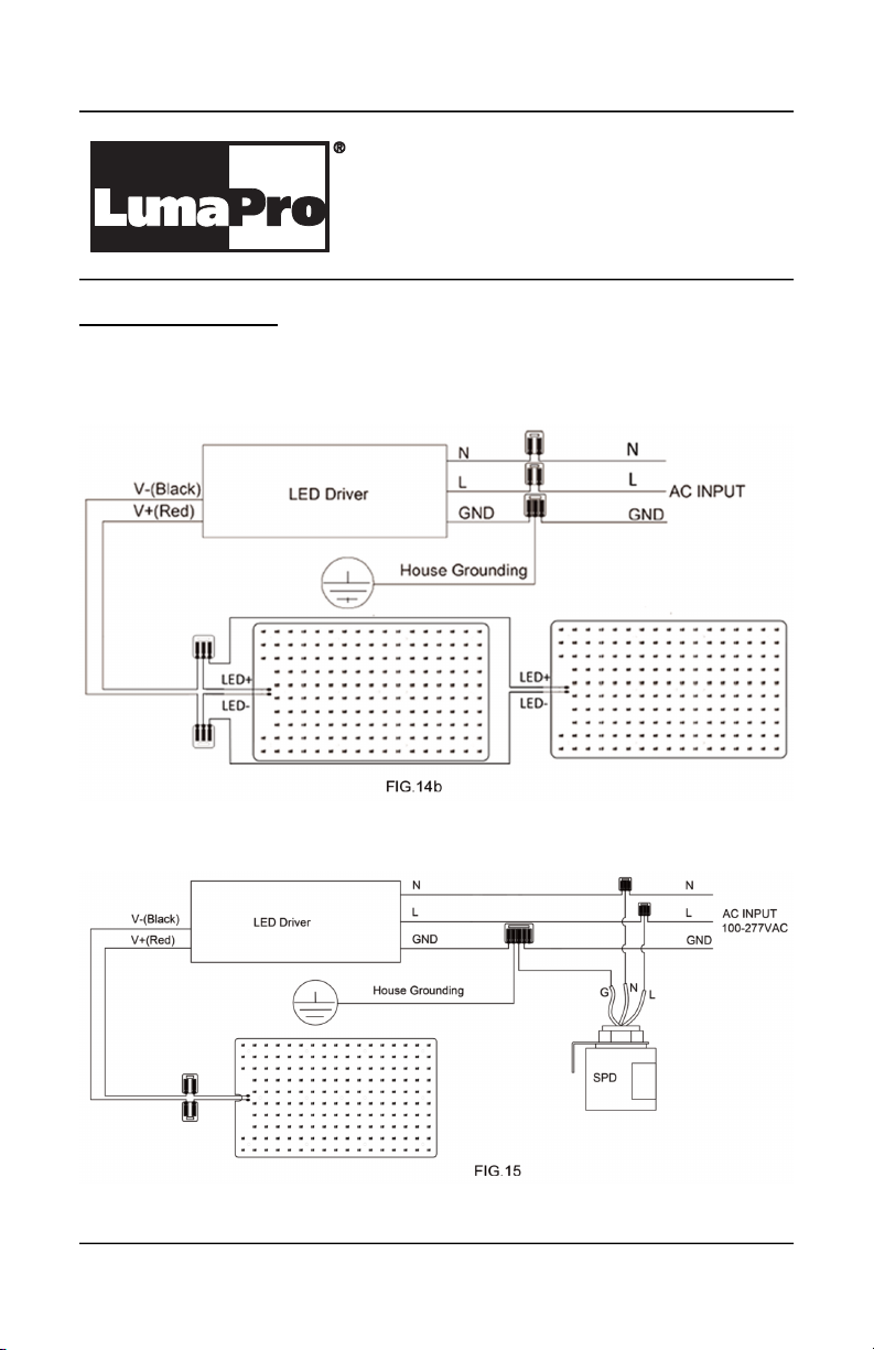
3. The FIG. 14 and FIG.15 demonstrate the interior wiring of different configurations in
the driver compartment (When need to remove or replace any component in the driver
compartment, please refer to the below wiring FIG. 14 and FIG. 15 and base on the
actual condition, resume using the fixture by wire connecting).
4. Disconnect the AC power supply to prevent electric shock when making wiring or
installation, removing or replacing any component in the fixture. Make sure to use
WAGO connector properly to ensure proper and secure wiring, make sure of correct
wiring before restoring power supply to light up the fixture.
Fixture wiring diagram:
1. FIG.14a is for wirings when only one LED driver is used in driver compartment,
no options.
7
LumaPro Operating Instructions
436R33, 446M61, 446M57, 446M58
LED Area Light
Fixtures
Wiring (Continued)
2. FIG.14b is for fixtures with two LED modules. This LED module to LED
driver connection can be used in the other configurations if there are two LED
modules.
3. FIG.15 is for wirings when surge protector is used.
 Loading...