

Page 1
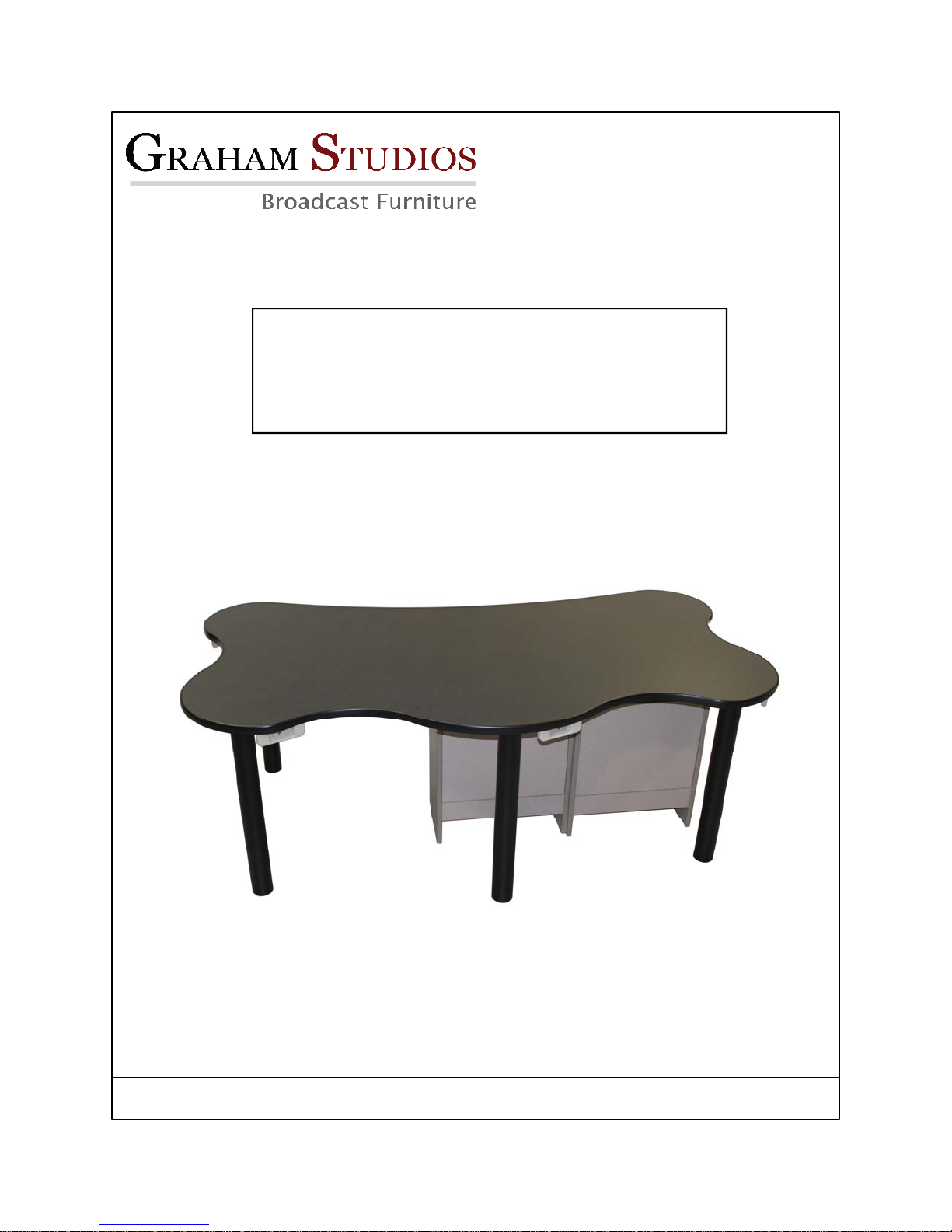
RXPC Talk Table
Instruction Manual
www.graham-studios.com ( 970 ) 225-1956
Copyright 2013 Graham Studios LLC
Page 2

This manual is a generic guide. The assembly of a Talk Table and is used as an
example. Your particular configuration may vary. Please refer to your personalized shop
drawing included in packaging.
Please call the factory if you have any questions at (970) 225-1956.
Tools needed :
1. #2 Phillips screw driver ( Power drill with barrel magnet makes it much easier )
2. 2 each— 7/16” open end wrenches
Table of Contents
1. Equipment/PBC cabinet assembly……………………………………….………...3
2. Attach stringers & Utility panel…………………………………… ………………..4
3. Install bases……………………………….………………………………………….5
4. Attach rear doors & Bolt cabinets together………………...……………………...6
5. Tabletop installation..……………………………………………………………….. 7
6. HP assembly………..………………………………………………………………...8
Care and Maintenance
Surfaces may be cleaned with mild soap and water.
Note : We will replace any damaged part at cost.
2
Page 3
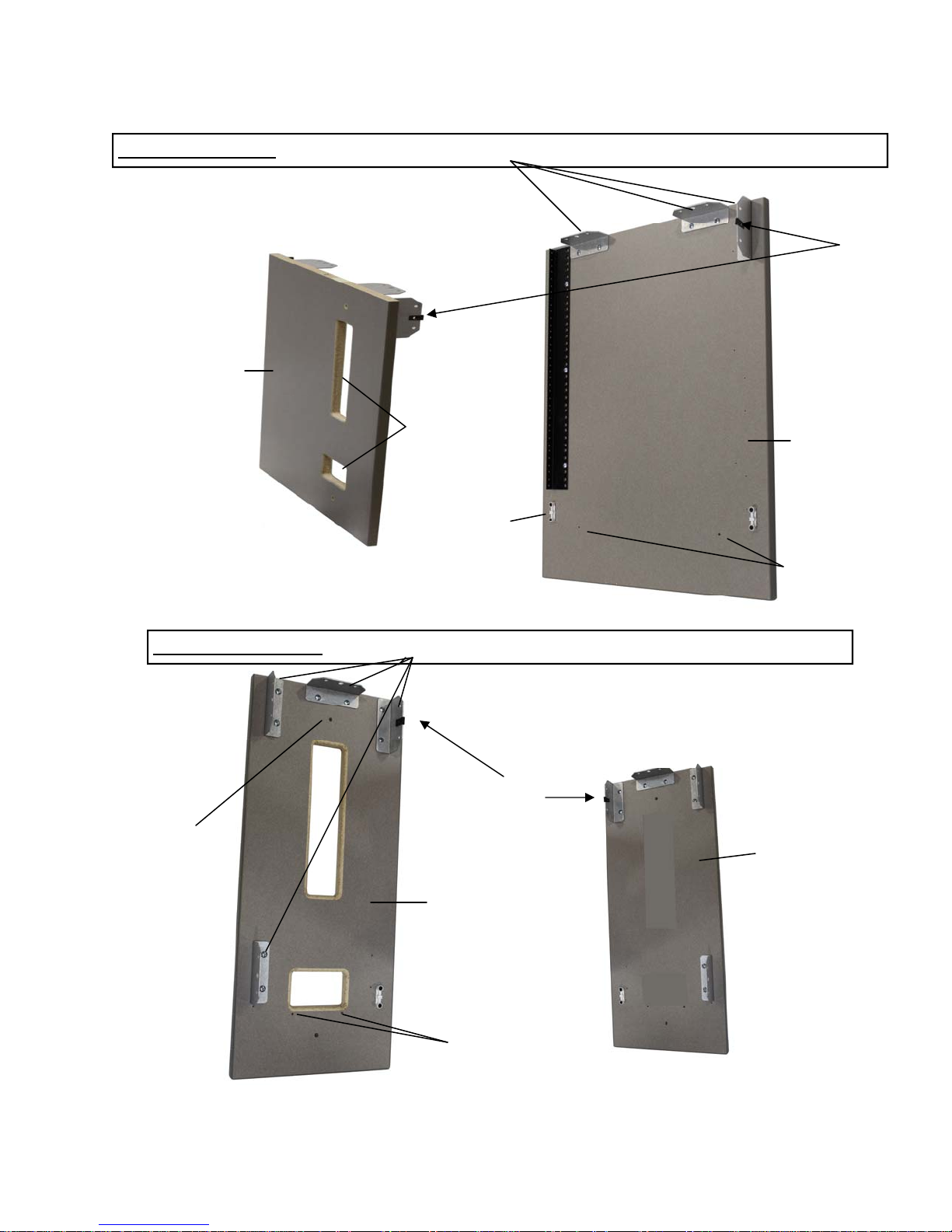
Equipment / PBC Cabinet Assembly
Equipment cabinet — Attach 3 Universal Brackets on each leg using 3/4 Truss head screws
Note : U Clip
on Rear of
each cabinet
Inside leg
Wire Egress
Surface
Mount
PBC / Utility Cabinet — Attach 4 Universal Brackets on each leg w/ 3/4 Truss head
Note: U Clip
on Rear of
Thru holes to
bolt cabinets
together
each cabinet
Outside leg
Outside leg
Hole for
shelf clip
Inside leg
Hole for shelf clip
3
Page 4
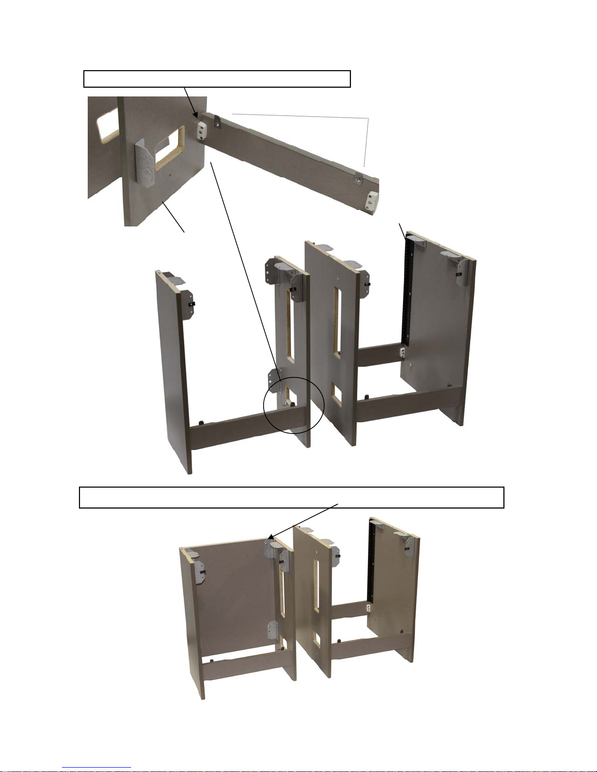
Attach Stringers to Both legs with surface mounts
Note : Door stops on Rear of cabinet
Utility / PBC cabinet leg
Rack rail
Equipment Cabinet
Utility/PBC Cabinet
Attach utility panel to punch block cabinet with 3/4 Truss head screws
4
Page 5
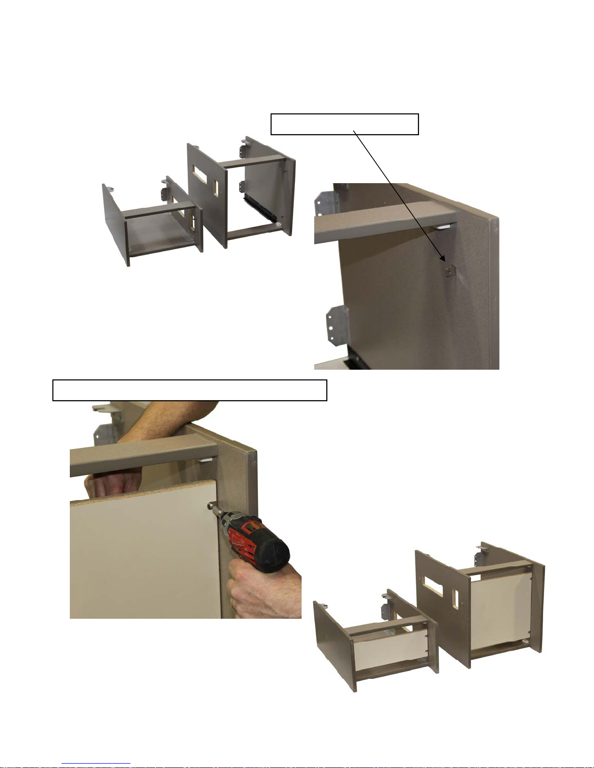
Install Bases
Lay cabinets on their sides
Insert 2 Clips on each leg
Secure bottom with #6 5/8 Phillips pan head screws
View of Bottoms installed
5
Page 6
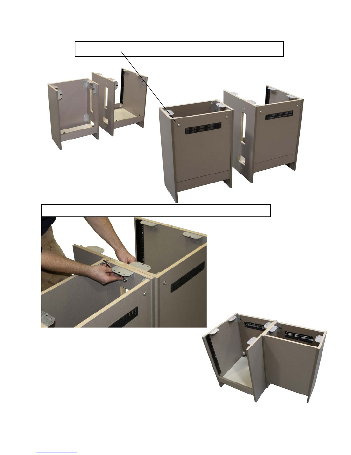
Attach Rear Door with 1/4 x 20 machine screws and finish washers
Equipment
Utility/PBC
cabinet
cabinet
Bolt Rack & PBC Cabinets together with 1/4 x 20 Bolts at top and bottom
Front view
6
Page 7
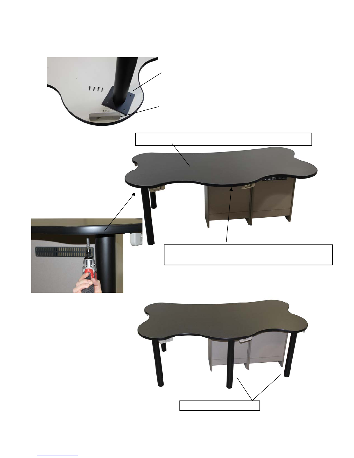
Tabletop Installation This step requires 2 people
Tabletop legs are secured with 1” Phillips pan head screws
in pre-marked areas
Note : Attaching HP Assembly can be done at this
time or after Top is installed ( See next page )
Place Top in position and Secure 2 metal Legs as shown
Locate pre-drilled holes and secure Cabinets to Top
with 3/4 Truss head screws
Secure last 2 metal legs
7
Page 8
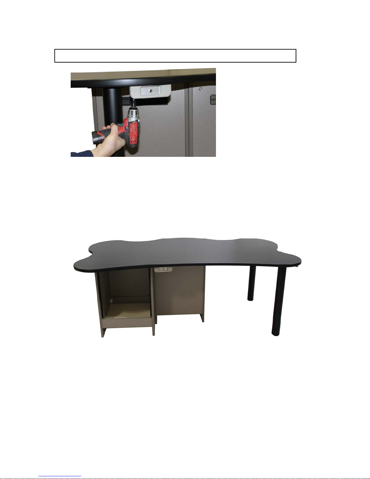
Attach HP Assembly at pre-drilled holes with 3/4 Truss head screws
Finished Talent view
8
 Loading...