

Page 1
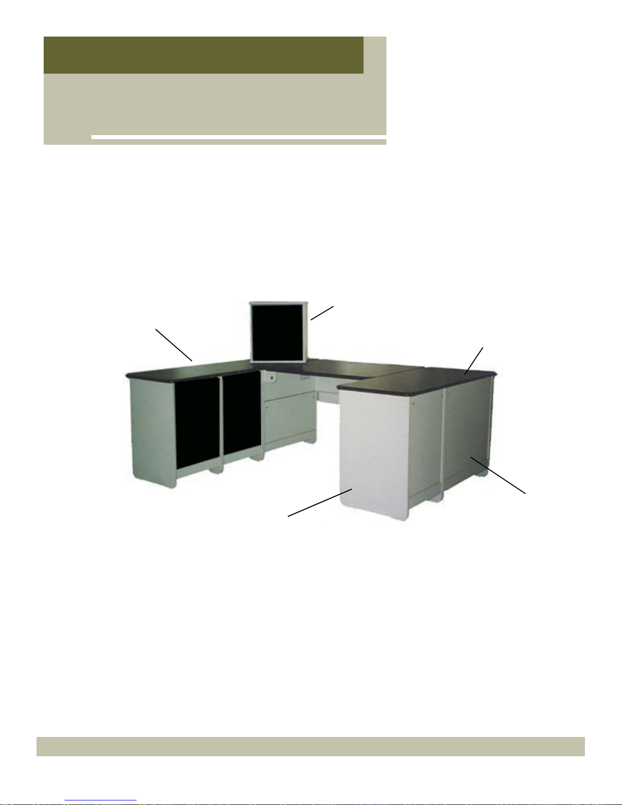
RADIUS-XP
Instruction Manual
...Studio furniture
Tabletops are high quality
plastic laminates
Melamine side
panels can not
delaminate and
are scratch and
wear resistant
Tabletop equipment
rack pod with heat
vent and rear access
All tabletops and
other panels are
laminated both sides
Rear access doors provide fast and convenient access to pedestal
interiors
This new studio line is engineered for studio decors where non-wood trims are a design goal. Available in a wide variety of colors, this furniture will complement any
size market application. The modular design enables the furniture to be ordered in
any configuration.
Graham Studios www.graham-studios.com (866) 481-6696
Page 2

otto
UB w/ U
She
p
ectors
otto
p
**Installati
on of the hardware
BEFORE
assembly is recommended
B
m
Universal Bracket
w/ U-cli
w/out Clip
Connector - Female
Inside Leg Outside Leg
UB w/ U-clip
Inside Stringer
Inside Door
M-panel
Door Stop
lf Cli
Male conn
Rear Door
Connector - Female
Rear Stringer
Universal Bracket
w/ U-clip
w/out Clip
-clip
Connector – female
Door Stop Bracket
Universal
Bracket w/ U-clip
Universal Brackets
RETURN PEDESTAL CABINET PARTS
Front Stringer Rear Stringer
Connector-
female
B
m
Outside Leg
Connector -
male
Shelf Clips
(typ 4P)
Door
Inside Leg
1 ¼ Ph screw
w/ washer
Universal
Bracket
w/ U-Clip
Universal
Bracket
Rack Rail
Rack Rail Connectors- male
(typ 4P)
Page 3
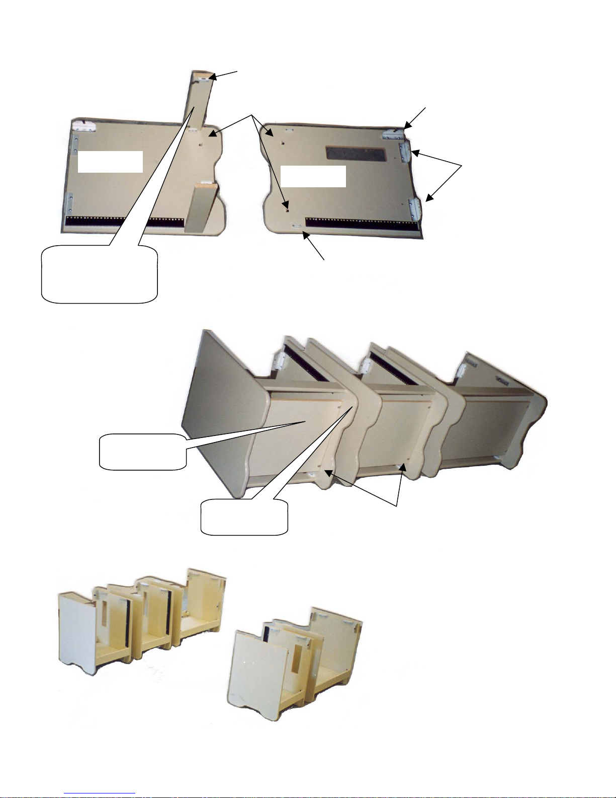
RETURN PEDESTAL ASSEMBLY
(typ
Connector - Female
Outside Leg
Attach Front & Rear
Stringers to outside leg
with ¼ turn connectors
- male/female
Shelf Clips
Figure 4
Inside Leg
Connector - Male
Universal bracket w/ U-Clip
Universal Brackets
4P)
Install bottom
to shelf clips
Figure 5
Secure inside
leg to stringers
Figure 6
Use #6 5/8 Phillips pan head screws
to secure shelf clip to bottom panel
Place pedestal cabinets
& return pedestals in
desired configuration
2
Page 4
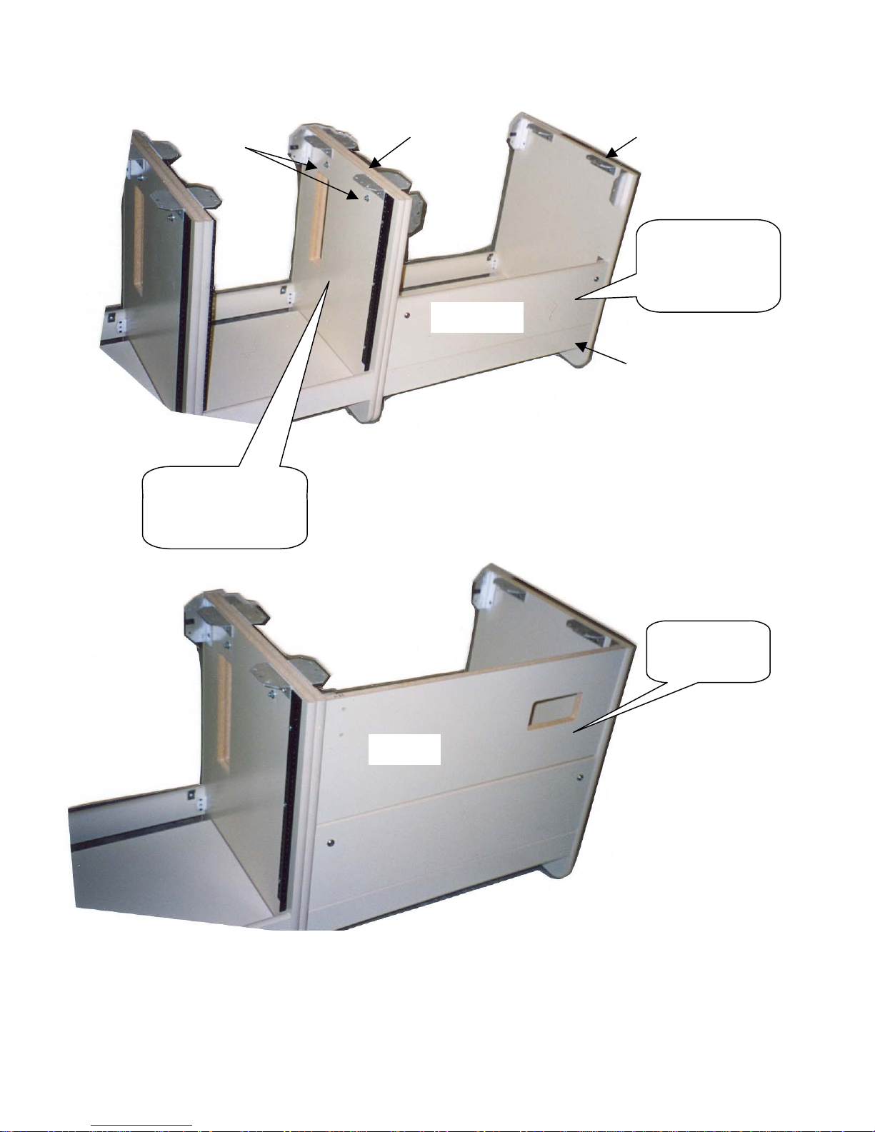
p
p
Inside leg for
¼ 20 x 2
Bolts
edestal
Outside leg
for
edestal
Install Inside door
w/ ¼ 20 x 1 ¼
phillips flat head
screw w/ washer
Inside Door
Inside Stringer
Figure 7
Connect Pedestal
cabinet to Return
Pedestals w/ ¼ 20 x 2
bolts
Install M-Panel
with wire egress
M-Panel
Figure 8
3
Page 5
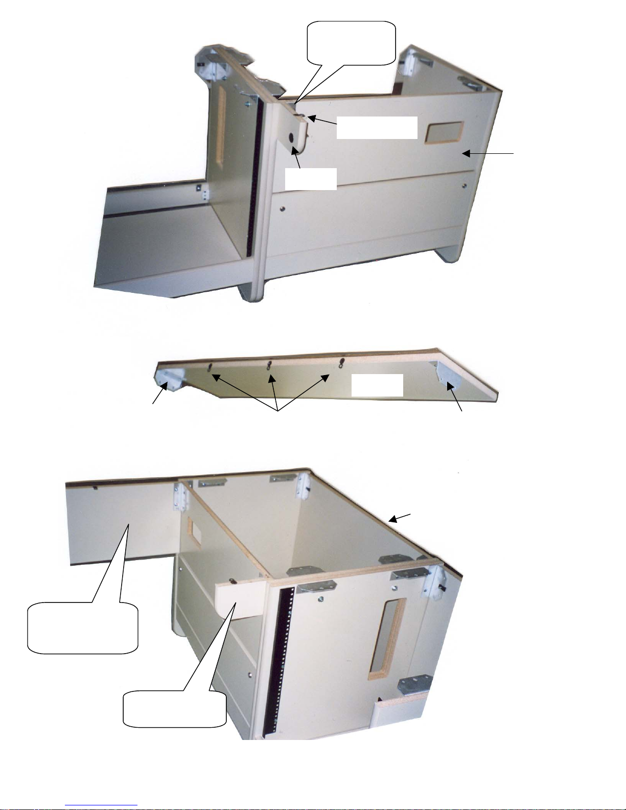
Secure left wing
p
w/ ¼ 20 bolts to
M-
HP jack
anel
Fig 8 connector
M-panel
Figure 9
** Populate M-panel
w/ hardware prior to
attaching to pedestals
Attach M-Panel to
right & left Pedestals
w/ ¼ 20 bolts
Universal
Bracket
Fig 8 connectors
M-Panel
Figure 10
Universal
Bracket
Rear door
Secure right wing
w/ ¼ 20 bolts
4
Figure 11
Page 6
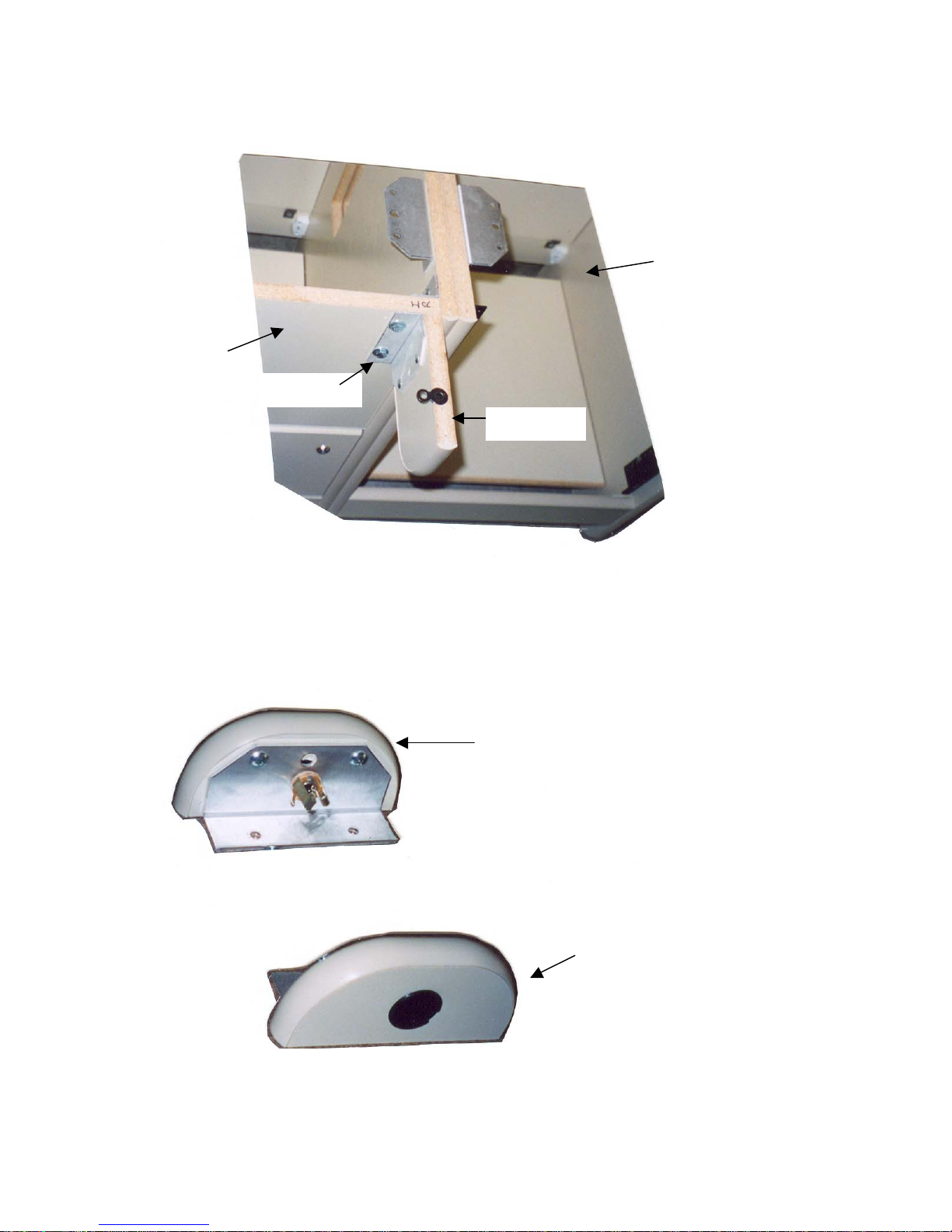
CLOSEUP OF WING ASSEMBLY
Return Pedestal
(Right Side)
Pedestal
¼ 20 Bolts
Right Wing
Figure 12
ACCESSORY ITEM FOR INTERVIEW LEDGES
HP Jack Assembly
Rear View
Front View
Figure 13
5
Page 7
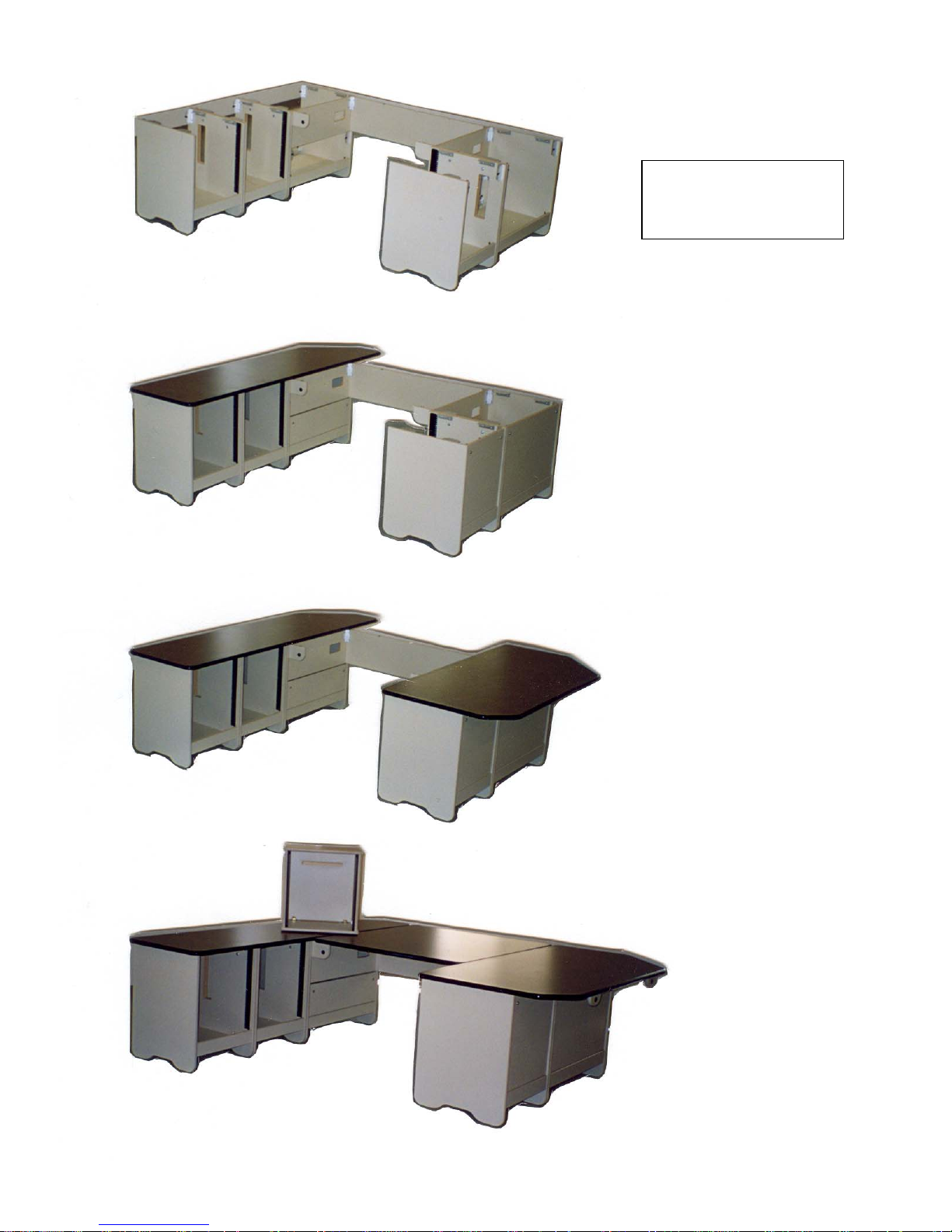
N
FINAL ASSEMBLY
Figure 14
**All hardware should be
installed prior to securing top
ote: Tabletops shown
include optional interview
ledges
Place first top on pedestals
Locate predrilled holes
Secure with #10 x ¾ truss
head screws
Leave loose until all tops
have been installed
Figure 15
Figure 16
Place second top on
pedestals
Locate predrilled holes
Secure with #10 x ¾ truss
head screws
Leave loose until all tops
have been installed
Place center top on
right & left wings
and m-panel
Secure with #10 x ¾
truss head screws
Adjusts as needed
for fit & tighten all
screws
Figure 17
6
Page 8
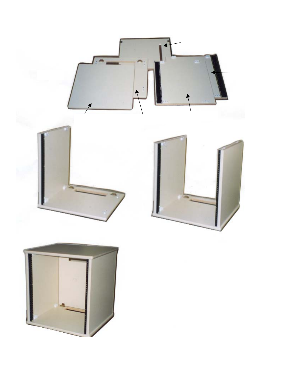
TABLE TOP EQUIPMENT RACK
Access Panel
Figure 1
Top Bottom
Right Side
Left Side
Figure 2
Figure 4
7
Figure 3
Locate Right, Bottom & Left sides as shown
in Figures 2 & 3
Using a phillips screwdriver tighten ¼ turn
connectors
Place Top over Side panels into ¼ turn
connectors & tighten
Put Access panel in place (magnet connectors
are preinstalled)
 Loading...