

Graham-Patten SoundPals, SoundPals DAC-20, SoundPals ADC-20, SoundPals DFADE-2, SoundPals DMIX-41 User Manual
...
SoundPals
User's Guide
™
interstage
Phistersvej 31, 2900 Hellerup, Danmark
Telefon 3946 0000, fax 3946 0040
www.interstage.dk
- pro audio with a smile

Printing History
SoundPals™ User’s Guide • Rev. B • January 1998 • Printed in U.S.A.
Part Number 08-2022-00A • The information contained in this guide is
subject to change without notice or obligation.
Copyright
© 1998 GRAHAM-PATTEN SYSTEMS, INC.
Contents of this publication may not be reproduced in any form without the
written permission of Graham-Patten. Reproduction or reverse engineering
of copyrighted software is prohibited.
FCC Compliance
This equipment has been tested and found to comply with the limits for a
Class A digital device pursuant to Part 15 of the FCC Rules. These limits are
designed to provide reasonable protection against harmful interference when
the equipment is operated in a commercial environment. This equipment
generates, uses, and can radiate radio frequency energy and, if not installed
and used in accordance with the instruction manual, may cause harmful
interference to radio communications. Operation of this equipment in a
residential area is likely to cause harmful interference in which case the user
will be required to correct the interference at his own expense.
Warranty Statement
Graham-Patten warrants that the equipment it manufactures is free from
defects in workmanship and materials and meets applicable published
specifications. Equipment that has been operated within published ratings and
has not been subjected to abuse or modification, and which fails because of
such defects, will be replaced or repaired at the Company’s discretion if it is
returned, freight prepaid, to Graham-Patten within 180 days of receipt.
This warranty supersedes all other Warranties, express or implied. GrahamPatten is not liable for any consequential damages.
NOTE
Filling out and returning the warranty registration card will
extend your SoundPals warranty to one year.
Company Address

GRAHAM-PATTEN SYSTEMS, INC.
Grass Valley, California 95945
Telephone: (800) 422-6662, (530) 273-
8412
World Wide Web: http://www.gpsys.com
P.O. Box 1960
Fax: (530) 273-7458
e-mail: soundpals@gpsys.com


Table of Contents
Introduction 1
About This Guide......................................................................................1
What are SoundPals .................................................................................2
Documentation Conventions..................................................................4
Documentation Terms ..............................................................................4
Abbreviations ............................................................................................5
Signals and Values....................................................................................5
Warnings ....................................................................................................5
Looping.......................................................................................................6
Unpacking and Inspection.......................................................................6
Power Supply Note...................................................................................6
DAC-20 7
About the DAC-20....................................................................................7
DAC-20 Installation................................................................................10
Connecting Power...........................................................................10
Connecting Inputs ..........................................................................10
Connecting Outputs .......................................................................10
DAC-20 Operation...................................................................................11
Using the Gain Controls .................................................................11
Using the Headphone Monitor.....................................................11
DAC-20 Interconnection........................................................................12
DAC-20 Internal Jumpers.......................................................................14
DAC-20 Troubleshooting......................................................................15
DAC-20 Specifications...........................................................................16
Audio Specifications......................................................................16
Environmental Specifications and Dimensions..........................16
SoundPals User's Guide Table of Contents • i

ADC-20 17
About the ADC-20..................................................................................17
ADC-20 Installation................................................................................20
Connecting Power...........................................................................20
Connecting Inputs ..........................................................................20
Connecting AES Reference...........................................................20
Connecting Outputs .......................................................................21
ADC-20 Operation...................................................................................21
Using the Gain Controls .................................................................21
Setting the Sample Frequency.......................................................21
ADC-20 Interconnection........................................................................22
ADC-20 Internal Jumpers.......................................................................24
ADC-20 Troubleshooting......................................................................25
ADC-20 Specifications...........................................................................26
Audio Specifications......................................................................26
Environmental Specifications and Dimensions..........................26
DFADE-2 27
About the DFADE-2...............................................................................27
DFADE-2 Installation.............................................................................30
Connecting Power...........................................................................30
Connecting Inputs ..........................................................................30
Connecting Outputs .......................................................................30
DFADE-2 Operation................................................................................32
Using the Gain Controls .................................................................32
Aligning Outputs ............................................................................32
Setting the DIP Switches................................................................33
DFADE-2 Interconnection.....................................................................34
DFADE-2 Remote Control ......................................................................36
Remote Control Connection..........................................................36
Remote Control Operation.............................................................38
DFADE-2 Internal Jumpers....................................................................40
DFADE-2 Troubleshooting...................................................................41
DFADE-2 Specifications........................................................................42
Audio Specifications......................................................................42
Remote Control Specifications......................................................42
Environmental Specifications and Dimensions..........................42
ii • Table of Contents SoundPals User's Guide

DMIX-41 43
About the DMIX-41................................................................................43
DMIX-41 Installation..............................................................................47
Connecting Power...........................................................................47
Connecting Inputs ..........................................................................47
Connecting Outputs .......................................................................48
DMIX-41 Operation................................................................................48
Local Operation...............................................................................48
AC-3 Operation................................................................................49
DMIX-41 Interconnection......................................................................49
DMIX-41 Remote Control......................................................................52
Remote Control Connection..........................................................52
Remote Control Operation.............................................................53
DMIX-41 Internal Jumpers.....................................................................55
Setting Output Channel Status.....................................................56
DMIX-41 Troubleshooting....................................................................57
DMIX-41 Specifications.........................................................................58
Audio Specifications......................................................................58
Remote Control Specifications......................................................58
Environmental Specifications and Dimensions..........................58
DMIC-20 59
About the DMIC-20................................................................................59
DMIC-20 Installation..............................................................................62
Connecting Power...........................................................................62
Connecting Inputs ..........................................................................62
Connecting AES Reference...........................................................62
Connecting Outputs .......................................................................63
Using Phantom Power....................................................................63
DMIC-20 Operation.................................................................................63
Adjusting Microphone Sensitivity...............................................63
DMIC-20 Interconnection......................................................................64
DMIC-20 Internal Jumpers.....................................................................66
DMIC-20 Troubleshooting....................................................................67
DMIC-20 Specifications.........................................................................68
Audio Specifications......................................................................68
Environmental Specifications and Dimensions..........................68
SoundPals User's Guide Table of Contents • iii

DA-14 69
About the DA-14.....................................................................................69
DA-14 Installation...................................................................................72
Connecting Power...........................................................................72
Connecting Inputs ..........................................................................72
Connecting Outputs .......................................................................72
DA-14 Operation and Application........................................................73
DA-14 Interconnection...........................................................................74
DA-14 Internal Jumpers..........................................................................76
DA-14 Troubleshooting.........................................................................77
DA-14 Specifications..............................................................................77
Environmental Specifications and Dimensions..........................77
Audio Specifications......................................................................78
DATS 79
About the DATS.....................................................................................79
DATS Installation...................................................................................80
DATS Specifications..............................................................................80
Appendix A. Inside the Module 81
In This Appendix .....................................................................................81
Before You Begin ....................................................................................81
Opening The Module .............................................................................82
Closing The Module...............................................................................83
Appendix B. External Power 85
About Power Supplies............................................................................85
CE Compliance.........................................................................................85
Portable Power Sources..........................................................................85
Power Supply Specifications.................................................................86
Power Supply Sources............................................................................86
Appendix C. Rack Tray 87
In This Appendix .....................................................................................87
Index 89
iv • Table of Contents SoundPals User's Guide

Introduction
About This Guide
This guide provides installation and operating instructions for GrahamPatten’s full line of SoundPals™ modular digital audio processing
products. The following chapters are included:
• The “Introduction” chapter describes the guide and introduces
the SoundPals products.
• The “DAC-20” chapter provides information on the DAC-20
AES digital-to-analog converter.
• The “ADC-20” chapter describes the ADC-20 stereo analog-
to-digital AES converter.
• The “DFADE-2” chapter describes the DFADE-2 stereo AES
two-channel digital fader.
• The “DMIX-41” chapter provides information on the DMIX-41
four-channel digital mixer.
• The “DMIC-20” chapter describes the DMIC-20 stereo digital
microphone pre-amplifier.
• The “DA-14” chapter describes the DA-14 AES 1-in 4-out
distribution amplifier.
• The “DATS” chapter describes the DATS (Digital Audio
Transmission System) converters.
• Appendix A, “Inside The Module” provides instructions for
opening and closing all SoundPals modules.
• Appendix B, “External Power” provides generic power supply
information for all SoundPals modules.
• Appendix C, “Rack Tray” provides instructions for installing
SoundPals modules in the optional Rack Tray.
A comprehensive index is also provided for your reference.
SoundPals User's Guide Introduction • 1

For simplicity and convenience in locating information in this guide,
each SoundPals chapter follows the same basic outline:
• Product Description • Interconnection
• Installation • Internal Jumpers
• Operation • Troubleshooting
• Remote Control (if applicable) • Specifications
What are SoundPals
Each Graham-Patten SoundPals module is essentially a digital audio
building block that can be used independently, or interconnected to
perform more advanced mixing and processing functions.
The following SoundPals modules are described in this guide:
• The DAC-20 is a stereo, 20-bit, AES digital-to-analog
converter that offers stereo headphone monitoring, automatic
detection and deemphasis, LED indicators for emphasis and
valid AES input, and analog output level adjustments.
• The ADC-20 is a stereo 20-bit, analog-to-digital AES converter
that offers adjustable input level, active balanced and
unbalanced outputs, and LED level indicators for normal and
overload conditions.
• The DFADE-2 is a stereo digital fader that offers local level
adjustment, unity gain switches for each channel, remote fade,
crossfade, channel-swapping and pan, 20-bit or 24-bit
processing, active balanced and unbalanced outputs, and LED
status indicators.
• The DMIX-41 is a four stereo-channel digital mixer that offers
remote input selection capability, 20-bit or 24-bit processing,
active balanced and unbalanced outputs, plus LED indicators
for continuous input status.
• The DMIC-20 is a dual microphone pre-amplifier with a built-in
20-bit analog-to-digital AES converter. The unit offers
adjustable microphone sensitivity, LED level indicators, and
coupling for phantom power.
• The DA-14 is a one-input, four-output “data regenerator” for
distributing AES digital audio signals. Versions are available
in both AES3 and AES3ID formats.
2 • Introduction SoundPals User's Guide

SoundPals can be used in both standalone and system configurations:
• In a “standalone” configuration, each SoundPals module is
designed to perform a specific audio processing function such
as digital-to-analog conversion or microphone pre-
amplification. In this way, each module functions as a perfect
low-cost adjunct to larger mixing consoles (such as the
Graham-Patten D/ESAM series) — for single-purpose digital
processing tasks.
• In a “system” configuration, SoundPals can be linked to form
more comprehensive digital audio tools. For both field
recording and studio applications, SoundPals can be used to
seamlessly perform functions that would otherwise require
extensive peripheral gear. Multi-purpose tasks such as
inserting analog equipment in a digital stream or adding
mix/fade capability to a workstation environment can be
performed with ease. Best of all, SoundPals “systems” can be
re-configured quickly and easily — to suit your changing
audio production requirements.
All SoundPals modules are extremely compact, rugged, and identical in
size for ease of installation, interconnection, and use. In addition,
SoundPals support AES3ID. This allows longer, more robust AES
signal distribution using standard coaxial cable. Error free distances of
1000 feet can be attained using inexpensive coaxial cables.
SoundPals User's Guide Introduction • 3

Documentation Conventions
The following documentation conventions are used in this guide:
• Buttons, knobs, connectors, and switches are indicated in
bold-faced capital letters. For example:
Adjust the left GAIN TRIM to …
• Primary sections are listed in bold text, with a line above:
Primary Section
• Secondary sections are listed in bold text, with no line:
Secondary Section
Documentation Terms
The following documentation terms are used throughout this guide:
• “Input” refers to a SoundPals module input, either analog or
digital. An analog input is a single monophonic track from an
analog audio source; a digital input represents two tracks
(stereo, left and right) from a digital audio source.
• “Output” refers to a SoundPals audio output, either analog or
digital. An analog output is a single monophonic track; a
digital output represents two tracks (stereo, left and right).
• “Source” refers to a monophonic or stereo device (analog or
digital) that is capable of generating an audio signal. Typical
sources are tape machines, audio mixers, and microphones.
• “Channel” refers to the specific left or right portion of the
stereo audio signal (digital or analog).
• “Unity Gain ” means that the audio output is equal to the input.
The signal is not adjusted, and simply passed through.
• “Gain Controls” are used to make level adjustments.
4 • Introduction SoundPals User's Guide

Abbreviations
The following abbreviations are used throughout this guide:
Abbreviation Description
AES Audio Engineering Society
ATR Audio Tape Recorder
DA Distribution Amplifier
DTR Digital Tape Recorder
GPS Graham-Patten Systems
Pot Potentiometer
SRC Sample Rate Converter
VTR Video Tape Recorder
Signals and Values
Note the following important information regarding signals and values:
• AES3 signals are balanced, 2–7 Vp-p at 110 Ω and use XLR
connectors.
• AES3ID signals are unbalanced, 1 Vp-p at 75 Ω and use BNC
connectors.
• 0 dBu = 0.778 Vrms
Warnings
Please observe the following important warnings:
• Heed all warnings on the unit and in the instructions.
• Do not use this product in or near water.
• Route power cords and other cables so that they are not likely
to be damaged. Disconnect power before cleaning. Do not
use liquid or aerosol cleaners; use only a damp cloth.
SoundPals User's Guide Introduction • 5

Looping
Looping between different SoundPals should only be attempted when
they are within approximately 3 feet of each other. Custom built Y
cables (for AES3 signals) or BNC T adapters (for AES3ID signals) must
be used for signal looping.
Unpacking and Inspection
When you receive your SoundPals modules, inspect the cartons for
signs of damage. Contact your dealer and the shipper immediately if
you suspect any damage has occurred during shipping. Check the
contents of each box to be sure that all parts are included. If any items
are missing, contact your dealer immediately.
NOTE Remember that filling out and returning the warranty
registration card will extend your SoundPals
warranty from 180 days to one year.
Power Supply Note
SoundPals are delivered with a power connector only. A separate
power solution must be obtained. Graham-Patten offers several power
solutions for both domestic and international customers. Refer to
Appendix B, “External Power,” for detailed power specifications for
users who wish to configure their own power solutions, rather than
purchase one from Graham-Patten.
6 • Introduction SoundPals User's Guide

DAC-20
About the DAC-20
The SoundPals DAC-20 is a stereo, 20-bit, AES digital-to-analog
converter. The unit offers the following features:
• Stereo headphone monitoring with level control
• 20-bit D/A converter
• Automatic detection and deemphasis
• LED indicators for emphasis and valid AES input
• Separate analog output level adjustments
(-10 to +4 dBu at -20 dBFS)
• Terminating or bridging input
• Optional rack mounting tray (1 RU)
• Compact size, rugged construction
The DAC-20 takes one AES input (on an XLR or BNC connector) and
converts it to two analog outputs (on XLR connectors).
SoundPals User's Guide DAC-20 • 7
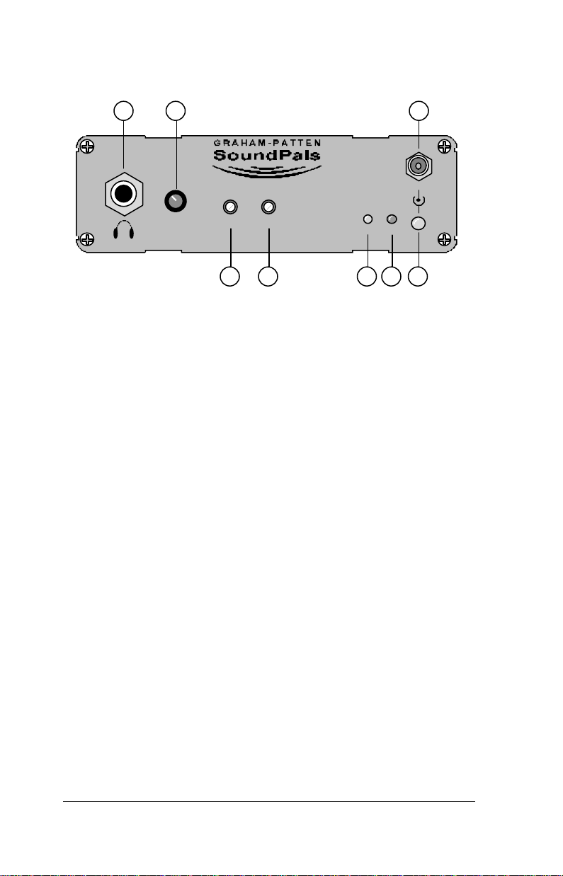
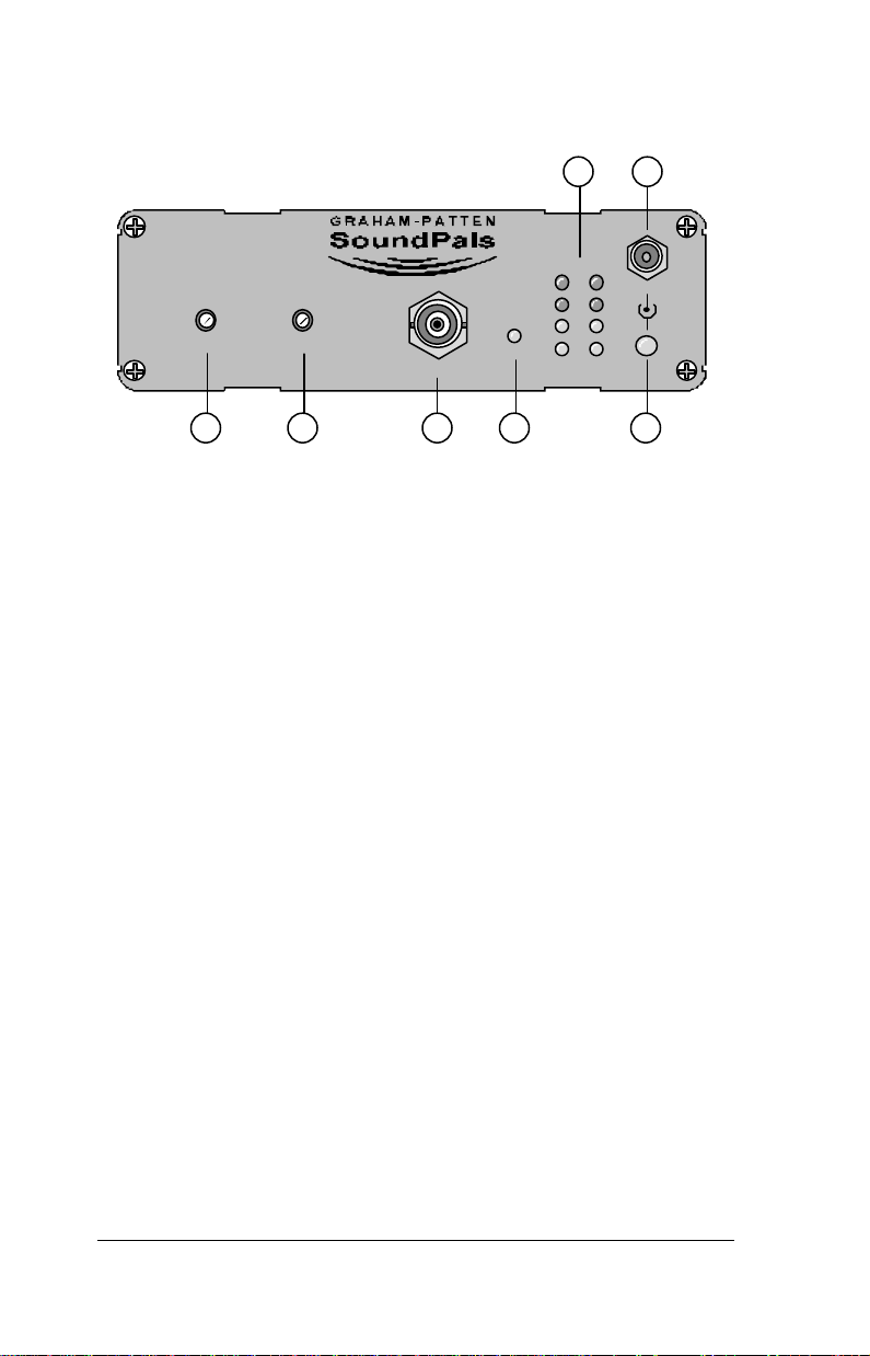
The figure below illustrates the DAC-20’s front panel:
ERR
7
+6V
DAC-20
8
65
1 2
DAC-20
VOLUME L R
GAIN
3
EMPH
4
1) Stereo Headphone Connector — accepts standard low-
impedance stereo headphones.
2) Headphone Gain Control — adjusts stereo headphone volume.
The control does not affect analog output levels.
3) Left Analog Output Gain Trim — the L GAIN trim sets the
analog line level for the left channel output.
4) Right Analog Output Gain Trim — the R GAIN trim sets the
analog line level for the right channel output.
5) Emphasis Detection LED — the EMPH LED lights when the
channel status bits of the AES input signal indicates that preemphasis has been applied to the signal. If the sampling
frequency is within 4% of 48 kHz, 44.1 kHz or 32 kHz, deemphasis correction is automatically applied.
6) AES Input Error LED — the ERR LED lights when no signal
is applied to the AES input, or when the signal is not valid. A
non-valid signal exhibits errors such as format violations, bit
errors, low level, or incorrect frequency.
7) Power Connector — accepts the power jack from the 6 VDC
power supply. Refer to Appendix B for more information
regarding external power.
8) Power LED — the large green LED below the power jack lights
when power is applied.
8 • DAC-20 SoundPals User's Guide
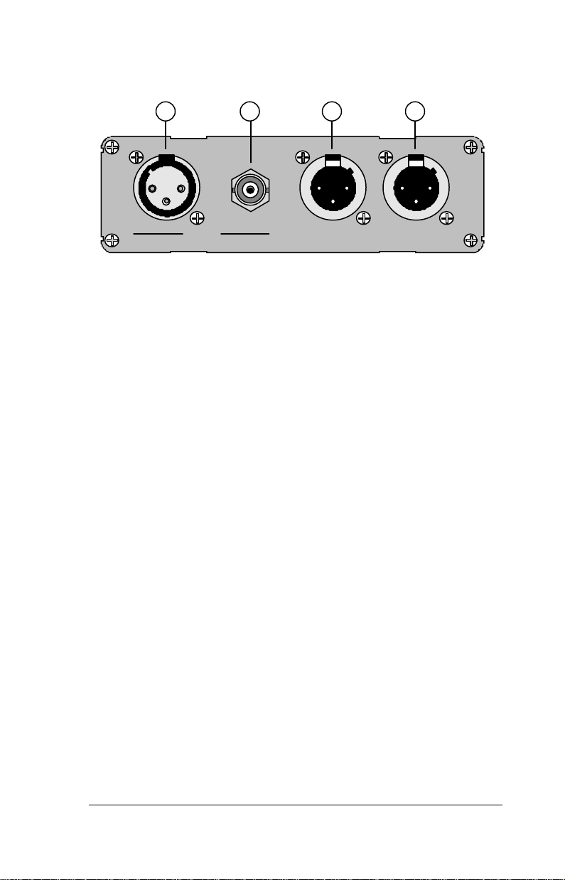
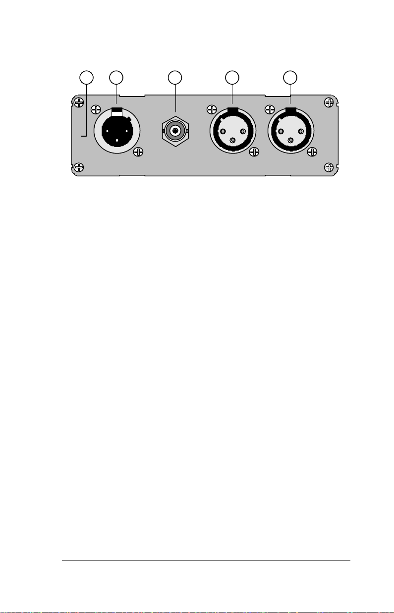
The figure below illustrates the DAC-20’s rear panel:
1 2 3 4
AES IN RIGHT OUT LEFT OUT
1) AES Balanced Input — the AES IN XLR connector accepts a
balanced AES input signal.
2) AES Unbalanced Input — the AES IN BNC connector accepts
an unbalanced AES input signal.
NOTE Do not connect both AES inputs at the same time.
3) Right Channel Analog Output — provides decoded right
channel output at analog line level, adjustable via R GAIN on
the front panel.
4) Left Channel Analog Output — provides decoded left channel
output at analog line level, adjustable via L GAIN on the front
panel.
MADE IN THE USA
SoundPals User's Guide DAC-20 • 9

DAC-20 Installation
This section provides instructions for connecting power, AES inputs,
and analog outputs.
NOTE For information on rack mounting the DAC-20 with
the optional rack tray, refer to Appendix C.
Connecting Power
Plug a 6 VDC power supply into the appropriate voltage outlet for your
specific country, and connect the end of the cord into the DAC-20 jack
marked +6V. Secure the locking ring finger tight. The green LED below
the jack lights when power is applied.
Connecting Inputs
Connect a digital input signal, between 30 kHz and 50 kHz sampling
frequency, to one of the two inputs marked AES IN. The ERR LED on
the front panel will light until a valid input signal is applied.
NOTE Do not connect both AES inputs at the same time.
The inputs are normally terminated internally with 110 Ω (AES3) and 75
Ω (AES3ID). When you need to loop an input signal to several
SoundPals, the signal must be terminated only once, and always at the
last unit in the chain. Refer to the “DAC-20 Internal Jumpers” section
for information on changing the input termination.
Connecting Outputs
Connect the analog audio outputs from the LEFT OUT and RIGHT
OUT connectors to the inputs of the desired analog destination device.
Please note:
• Balanced outputs are taken from pins 2 (+ve) and 3 (−
pin 1 and the shell grounded.
• Unbalanced outputs are taken from pin 2 with pin 1 and the
shell grounded.
CAUTION Do not connect pin 3 to the low (grounded) side of
an unbalanced load.
See the “DAC-20 Operation” section for instructions on adjusting level
for conditions other than +4 dBu reference with 20 dB headroom.
10 • DAC-20 SoundPals User's Guide
ve
) with

DAC-20 Operation
This section provides instructions for using the gain controls, aligning
outputs, and adjusting the headphone monitor.
Using the Gain Controls
For setting left and right output levels, each output has its own level
adjustment on the front panel. Outputs are factory-set for +4 dBu at 20 dBFS. Other levels can be set by using the following alignment
procedure:
To align the left and right analog outputs:
1. Connect a reference digital tone generator to the DAC-20’s
AES IN connector.
2. Connect analog VU meters to the LEFT OUT and RIGHT
OUT connectors.
3. Turn on the digital reference tone, and while metering the
analog output levels, adjust the associated L and R trimmers
for the desired output level.
Using the Headphone Monitor
The analog outputs may be monitored with a pair of stereo headphones
plugged into the headphone jack. Best results are obtained with a
headphone impedance of 20–50 Ω. Use the associated stereo
VOLUME control to set a comfortable listening level.
SoundPals User's Guide DAC-20 • 11

DAC-20 Interconnection
SoundPals DAC-20
SoundPals ADC-20
This section provides basic and advanced interconnection diagrams.
• Basic — Monitoring Digital Signals
In this basic application, connect the DAC to an AES patch
panel. You can then quickly monitor the signal on any circuit,
using either headphones or VU meters.
AES Jackfield
Analog VU Meters
Stereo
Headphones
• Basic — Inserting Analog Equipment
In this application, an analog ATR is seamlessly inserted in a
digital stream, using both the DAC and ADC together.
AES
Input
AES In
AES In
Right Out
Left Out
PWR
R Trim
L Trim
Volume
Headphones
Analog
ATR
AES In
AES In
Right Out
Left Out
SoundPals DAC-20
AES Out
AES Ref
Right In
Left In
PWR
R Trim
L Trim
Volume
Headphones
AES
Output
PWR
AES Out
R Trim
L Trim
12 • DAC-20 SoundPals User's Guide
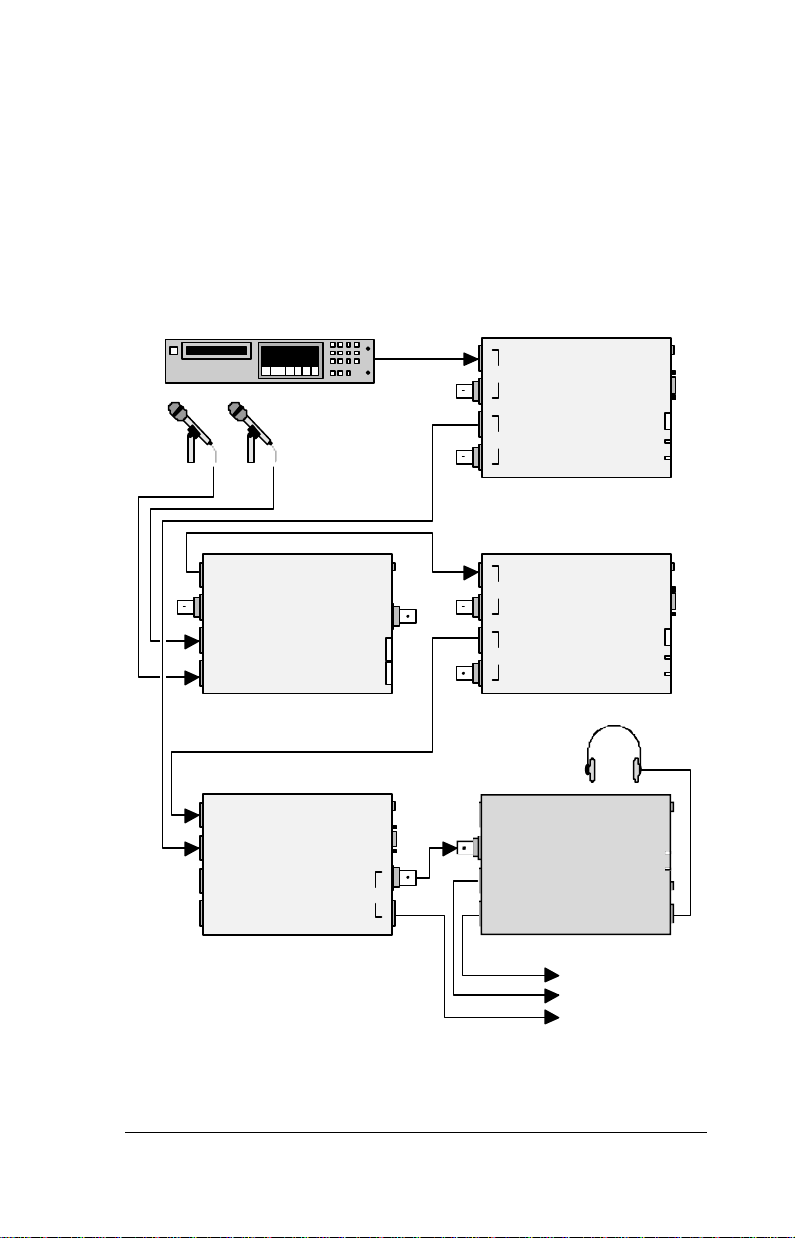
• Advanced — Simultaneous Multi-Format Outputs
Digital Out
In this application, SoundPals are combined in a sub-mix
configuration. A CD player feeds a DFADE for level control,
and then a DMIX. Dual mics are converted to digital, routed to
a DFADE for level control, and then to a DMIX. One DMIX
output provides a digital feed, while the other is converted to
analog using a DAC. Thus the mix is available in both analog
and digital formats simultaneously.
CD Player
AES In
Analog
Microphones
AES Out
SoundPals DFADE-2
PWR
Control
Mode
R Trim
L Trim
AES Out
AES Ref
Right In
Left In
SoundPals DMIC-20
AES In 1
AES In 2
AES In 3
AES In 4
SoundPals DMIX-41
PWR
AES Out
Sensitivity
PWR
Control
AES Out
AES In
AES Out
SoundPals DFADE-2
Stereo
Headphones
AES In
AES In
Right Out
Left Out
SoundPals DAC-20
Analog Out (L)
Analog Out (R)
PWR
Control
Mode
R Trim
L Trim
PWR
R Trim
L Trim
Volume
Headphones
SoundPals User's Guide DAC-20 • 13
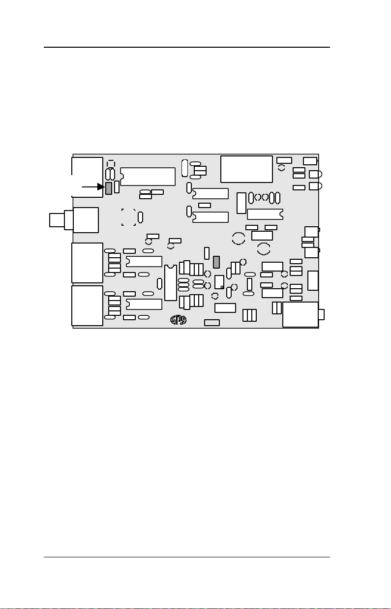
DAC-20 Internal Jumpers
This section provides information about the DAC-20’s internal jumpers
and adjustments.
NOTE For detailed instructions on opening and closing the
DAC-20, see Appendix A, “Inside the Module.”
The figure below shows the DAC-20’s internal jumper locations:
Input
Termination
Jumper
J1
J3
DAC
04-0223-
• To change the AES input from terminating to bridging, remove
jumper J1.
14 • DAC-20 SoundPals User's Guide

DAC-20 Troubleshooting
The table below lists several DAC-20 problems, and provides a variety
of “checklist” procedures designed to solve them.
Problem Procedure
No signal at
any analog
output.
• Is power applied? Check the power
LED and power supply.
• Is a valid AES input signal
connected? Check ERR LED off.
• Is the input signal silent? Check the
signal source.
No audio on
XLR outputs.
No audio on
headphone
output.
Emphasis on
input is not
corrected.
• Are the outputs connected correctly?
Check +ve to pin 2, −ve to pin 3
(balanced) or hot to pin 2, ground to
pin 1/shell, pin 3 open (unbalanced).
• Is the volume control turned up?
• Is the phone jack connected
correctly? Check left hot to tip, right
hot to ring, ground to sleeve.
• Does AES channel status indicate
emphasis? Check EMPH LED on.
• Is the sampling frequency within 4%
of 48 kHz, 44.1 kHz or 32 kHz?
• Does the emphasis use 50/15 µs time
constants?
NOTE Please contact the GPS factory if the problem still
exists after completing the above procedures.
SoundPals User's Guide DAC-20 • 15

DAC-20 Specifications
This section provides audio and environmental specifications.
Audio Specifications
Parameter Specification
Digital input Terminated (110 Ω AES3, 75 Ω AES3ID)
Sample Rate 30 kHz – 50 kHz
Analog Outputs
Impedance 30 Ω
Level range −5 dBu to +12 dBu at −20 dBFS
Maximum output @ 86dB THD+N
+24 dBu (bridging load)
+22 dBu (600 Ω load)
Frequency
response
Crosstalk <−84 dB, 20 Hz – 10 kHz
Dynamic range 94 dB
Impedance 20 Ω
Frequency
response
Dynamic range 91 dB
+0/−0.2 dB, 20 Hz – 20 kHz
Headphone Output
+0/−0.2 dB, 50 Hz – 20 kHz
NOTE
• All specifications listed above subject to
change without notice.
• All parameter s listed above specified at 48 kHz
sampling frequency.
Environmental Specifications and Dimensions
Parameter Specification
Dimensions
(less connectors)
Power 375 mA @ 6 Vdc
16 • DAC-20 SoundPals User's Guide
5.2W x 1.62H x 6.625D
13.2 x 4.1 x 16.8 cm

Operating Temp. 10 – 50 °C
Operating
Humidity
10 – 90% RH non-condensing
SoundPals User's Guide DAC-20 • 17


ADC-20
About the ADC-20
The SoundPals ADC-20 is a stereo 20-bit, analog-to-digital AES
converter. The unit takes two line-level analog inputs (on XLR
connectors), and converts them to one digital AES output (provided on
both XLR and BNC connectors simultaneously).
The ADC-20 offers the following features:
• 20-bit A/D converter
• Adjustable level for each input
(-10 to +4 dBu at -20 dBFS)
• AES reference input
• Active balanced and unbalanced outputs
• LED level indicators for normal and overload conditions
• Optional rack mounting tray (1 RU)
• Compact size, rugged construction
Two versions of the ADC-20 are available:
• 44.1 kHz Model
This model defaults to 44.1 kHz, via the internal crystal.
However, if an external reference is applied to the AES REF
connector, the output frequency will lock to the reference.
• 48 kHz Model
This model defaults to 48 kHz, via the internal crystal.
However, if an external reference is applied to the AES REF
connector, the output frequency will lock to the reference.
NOTE The printed legend on the rear panel indicates the
default frequency.
SoundPals User's Guide ADC-20 • 19
The figure below illustrates the ADC-20’s front panel:
ADC-20
L R
GAIN
AES OUT
EXT
REF
L R
0
-3
-20
-60
LEVEL
65
+6V
ADC-20
2
3 4 71
1) Left Analog Input Gain Trim — L GAIN sets the left
channel’s analog input level (the level that you want to
correspond to -20dB below digital clipping).
2) Right Analog Input Gain Trim — R GAIN sets the right
channel’s analog input level (the level that you want to
correspond to -20dB below digital clipping).
3) AES Unbalanced Output — provides AES unbalanced output
(BNC). Output is concurrent with the rear panel’s AES
balanced output (XLR) — both can be used simultaneously.
4) AES Reference LED — the EXT REF LED lights when the
sampling frequency is locked to the externally supplied AES
reference signal. The LED is an indication only, not an alarm.
5) Level Indicator LEDs — provides level indication for each
input (calibrated in dB). When properly adjusted, the
following levels are indicated:
• −−60 dB: signal present
• −−20 dB: normal digital reference level
• −−3 dB: approaching clipping
• 0 dB: A/D converter is clipping
6) Power Connector — accepts the power jack from the 6 VDC
power supply. Refer to Appendix B for more information
regarding external power.
7) Power LED — the large green LED below the power jack lights
when power is applied.
20 • ADC-20 SoundPals User's Guide
The figure below illustrates the ADC-20’s rear panel:
2 3 4 51
44.1 KHZ
AES OUT AES REF RIGHT IN LEFT IN
1) ADC Version — the printed legend indicates the default
frequency (either 44.1 kHz or 48 kHz).
2) AES Balanced Output — provides AES balanced output via
XLR connector. Output is concurrent with the front panel’s
AES unbalanced output (BNC) — both can be used
simultaneously.
3) AES Reference Input — the AES REF connector accepts an
AES reference signal (between 30 kHz and 50 kHz sampling
rate). Only timing information is used; audio content (if any) is
ignored. Refer to the “Connecting AES Reference” section for
information on switching frequencies via the reference signal.
4) Right Analog Input — accepts right channel line level analog
input. The input level is adjustable via R GAIN on the front
panel of the ADC.
5) Left Analog Input — accepts left channel line level analog
input. The input level is adjustable via L GAIN on the front
panel of the ADC.
MADE IN THE USA
SoundPals User's Guide ADC-20 • 21

ADC-20 Installation
This section provides instructions for connecting power, analog inputs,
AES reference, and digital outputs.
NOTE For information on rack mounting the DAC-20 with
the optional rack tray, refer to Appendix C.
Connecting Power
Plug a 6 VDC power supply into the appropriate voltage outlet for your
specific country, and connect the end of the cord into the ADC-20 jack
marked +6V. Secure the locking ring finger tight. The green LED below
the jack lights when power is applied.
Connecting Inputs
Connect left and right channel analog inputs to the two rear connectors
marked LEFT IN and RIGHT IN. Balanced sources are connected to
pins 2 (+ve) and 3 (−
sources are connected to pin 2 with pins 1, 3 and the shell grounded.
Refer to the “ADC-20 Operation” section for instructions on correctly
adjusting input level.
Connecting AES Reference
The ADC-20 can be synchronized to an alternate output frequency
(from the default frequency) by connecting a valid AES reference signal
to the AES REF BNC connector. The EXT REF LED on the front
panel lights when a valid reference signal is applied.
ve
) with pin 1 and the shell grounded. Unbalanced
To phase lock the unit’s sample frequency to a reference, connect a
reference signal (between 30 kHz and 50 kHz sampling rate) to the AES
REF BNC connector. The AES signal output will now phase-lock to the
incoming reference — independent of the ADC’s default reference
frequency.
Note that the AES REF input is normally terminated internally with 75
Ω. When it is necessary to loop reference to several SoundPals, the
signal must be terminated only once, and always at the last unit in the
chain. Refer to the “ADC-20 Internal Jumpers” section for information
on changing the input from terminating to bridging.
22 • ADC-20 SoundPals User's Guide
 Loading...