

Graham-Patten D/ESAM 8000 Installation Manual
D/ESAM 8000
Installation Guide
Revision 1.6a
December 12, 2002


Table of Contents
Introduction .......................................................................................1
Overview....................................................................................1
System.......................................................................................2
Dimensions ........................................................................................3
Control Panel...............................................................................3
CPU Controller.............................................................................4
Vadis Chassis ..............................................................................4
System Interconnection........................................................................5
Basic Connections ........................................................................5
Ethernet Connections ....................................................................6
Sync/Reference Connection............................................................8
RS-422 Editor Remote Connection...................................................8
Audio Inputs.....................................................................................11
SDI Input .................................................................................11
AES Input .................................................................................12
Audio Outputs...................................................................................13
AES Output ...............................................................................14
Analog Output ...........................................................................15
Audio Connector Panels ......................................................................16
GPI Input Connections .......................................................................17
Boot-Up Procedures...........................................................................18
Contact Information ...........................................................................19


D/ESAM 8000 – Installation Guide
Introduction
Overview
This guide provides information for the installation of the D/ESAM 8000 audio
mixer. The following information is covered in this Installation Guide:
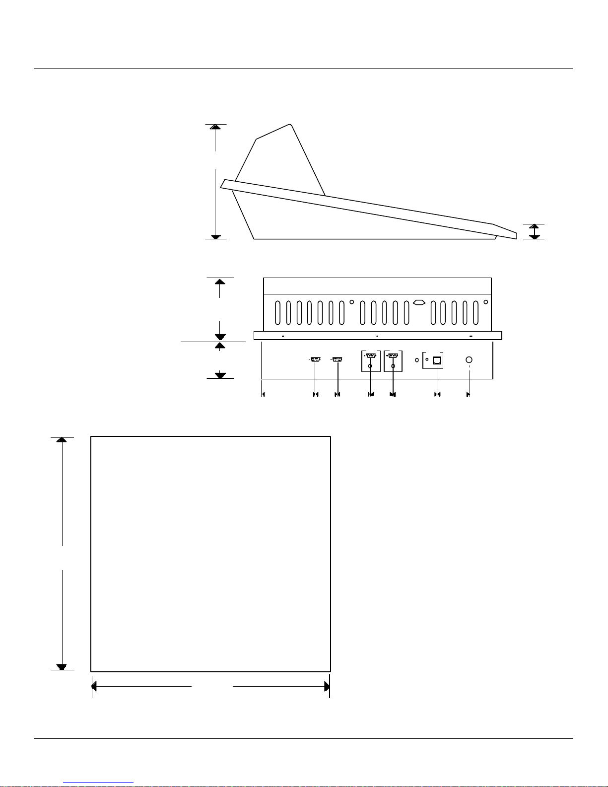
Dimensions (page 3)
Diagrams showing dimensions for the control panel, CPU
controller and Vadis chassis.
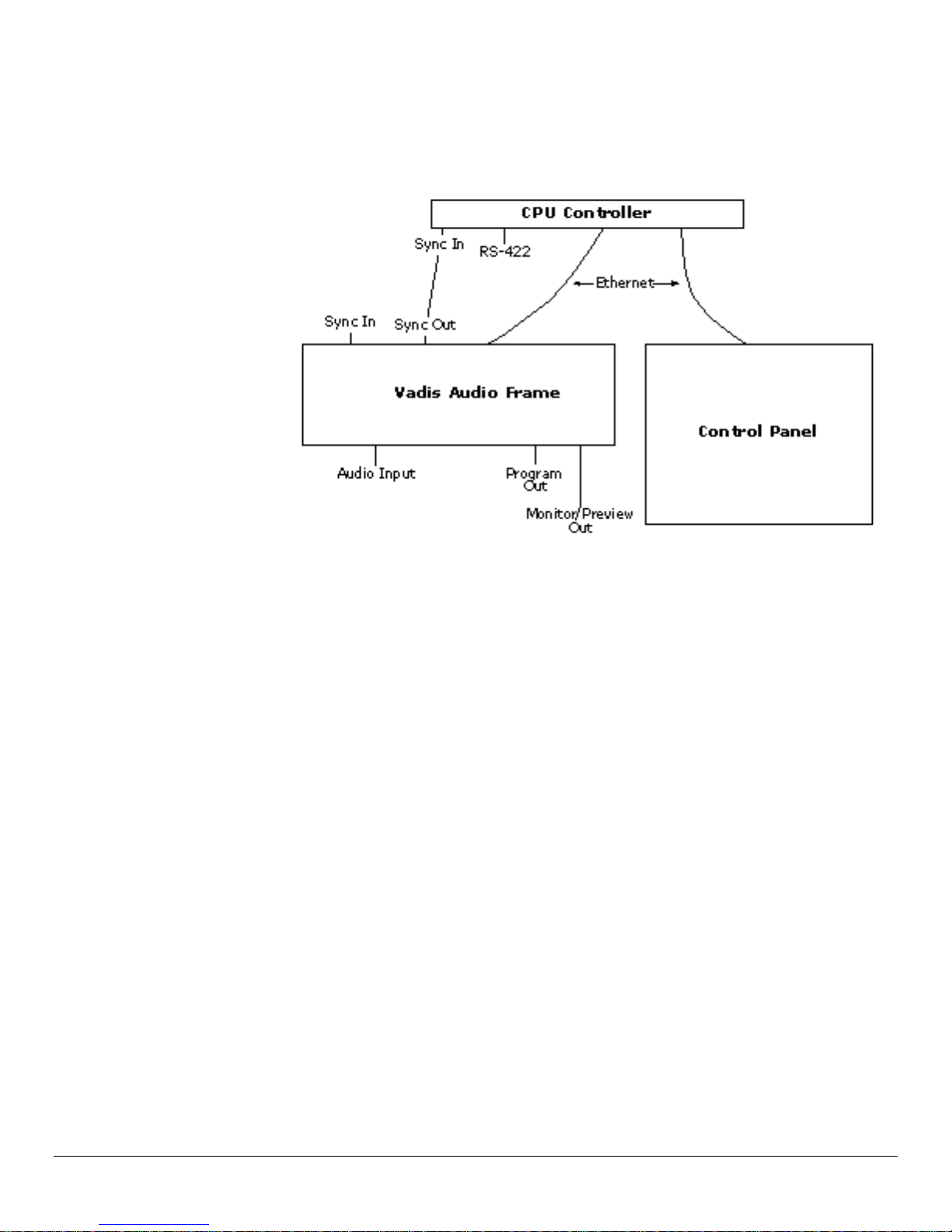
System Interconnection (page 5)
Information and diagrams outlining the basic system
connections including sync and Ethernet.
Audio Inputs (page 11)
Information and diagrams about audio inputs.
Audio Outputs (page 13)
Information and diagrams about audio outputs.
Audio Connector Panels (page 15)
Information and diagrams about audio connector panels.
GPI Input Connections (page 17)
Connector pinout diagram and other info for GPI input
connections.
Boot-Up Procedures (page 18)
This section shows you how to properly boot up and re-boot
the D/ESAM 8000.
Introduction 1
System
D/ESAM 8000 – Installation Guide
Before we begin, here is an overview of the D/ESAM 8000 system. The
D/ESAM 8000 consists of three units: the CPU controller, the Vadis audio
chassis and the mixer control panel.
2 Introduction
D/ESAM 8000 – Installation Guide
1.10 inches
Dimensions
Control Panel
8.77 inches
222.76 mm
27.94 mm
5.70 inches
(144.8 mm)
20 inches
(508 mm)
Console
Surface
3.36 inches
(85.3 mm)
Control Panel
Cutout
Dimensions
4.84
(123)
2.00
(51)
SpareMaint
3.00
(76)
MeterStatus
2.00
(51)
Reset
4.00
(102)
Active
Rack I/O
Link
P ower
2.91
(74)
FRONT
21 inches
(533.4 mm)
Dimensions 3
 Loading...