

Graham Corporation Liquid Ring Pump 2 Series Installation, Operation & Maintenance Manual

Graham Corporation
Table of Contents
Section 1 - General Information ................................................................................................... 3
1.1 Introduction......................................................................................................................................3
1.2 General Description and Principle of Operation..............................................................................4
1.3 Description of Pump Model Codes .................................................................................................. 5
Section 2 - Installation Instructions .............................................................................................. 6
2.1 Handling........................................................................................................................................... 6
2.2 Preservation...................................................................................................................................... 6
2.3 Mounting..........................................................................................................................................6
2.4 Installation........................................................................................................................................ 6
2.5 Coupling Alignment......................................................................................................................... 7
2.6 Belt Drives .......................................................................................................................................8
2.7 Service Liquid Piping Arrangements ............................................................................................... 8
2.8 Shaft Seal Coolant Piping Arrangement ........................................................................................ 11
2.9 Piping Requirements ...................................................................................................................... 11
2.10 Electrical Requirements ............................................................................................................... 12
Section 3 - Operating Instructions ..............................................................................................12
3.1 Start-up Procedures ........................................................................................................................ 12
3.2 Pump Packing Adjustment............................................................................................................. 13
3.3 Service Liquid Requirements.........................................................................................................14
3.4 Cavitation ....................................................................................................................................... 15
3.5 Shut-Down Procedure .................................................................................................................... 16
Section 4 - Accessory Items........................................................................................................ 16
4.1 Accessories..................................................................................................................................... 16
Section 5 - Maintenance.............................................................................................................. 19
5.1 Performance ................................................................................................................................... 19
5.2 Pump Estimated Weights ............................................................................................................... 19
5.3 Shaft Bearings ................................................................................................................................ 19
5.4 Gland Packings ..............................................................................................................................19
5.5 Mechanical Seals............................................................................................................................ 19
5.6 Storage ...........................................................................................................................................20
5.7 Removal from storage....................................................................................................................20
5.8 Troubleshooting Chart ...................................................................................................................21
Section 6 - Rebuild Instructions.................................................................................................. 22
6.1 General ........................................................................................................................................... 22
6.2 Impeller End Clearances ................................................................................................................ 22
6.3 Tie Rod Torque Values .................................................................................................................. 24
6.4 Bearing Data .................................................................................................................................. 24
Section 7 - Warranty ................................................................................................................... 25
Appendix A- Material Safety Data Sheets.................................................................................. 26
Appendix B- Return Material Authorization Form .................................................................... 29
Appendix C- Pump Information ................................................................................................. 30
Appendix D- Pump Weights.......................................................................................................31

Graham Corporation
Section 1 - General Information
1.1 Introduction
This manual will provide assistance in the installation, operation, and maintenance of your
Graham Liquid Ring Pump. Please read this manual completely prior to operating your Liquid
Ring Pump. If you need to contact the Pump Service Department for assistance, please have
available the pump serial number and model number. The Pump Service Department may be
reached by contacting Graham Corporation in Batavia, NY by phone (585) 343-2216, Fax (585)
343-1097, or e-mail at service@graham-mfg.com. Refer to the Graham web site at
www.graham-mfg.com for other information on our Liquid Ring Pumps.
Graham has an extensive stock of spare parts and replacement pumps. Stocked parts and pumps
can be shipped from our warehouse in Batavia, NY by a carrier of your choice.
For your convenience, use our toll free number (1-800-828-8150) only when ordering spare parts
and replacement pumps. Please have the model number, serial number and part number of the
items required when placing an order. Refer to Graham web site www.graham-mfg.com for
Liquid Ring Vacuum Pump spare parts information. Normal business hours are 8:00 a.m. to 5:00
p.m. (E.S.T.), Monday through Friday.
Factory rebuilding service is available for pumps returned to our factory in Batavia, New York.
Before a pump is returned to the factory for repairs, please drain and flush the pump and include
a Material Safety Data Sheet (MSDS) for the process in which the pump was used. A Return
Material Authorization (RMA) Number, issued by Graham, is required before returning a pump.
Refer to our web site for this form or contact Graham for this information. Field Service
Technicians are also available for travel to the jobsite for troubleshooting and repair or
rebuilding of pumps. Contact Graham for service rates.
This document and the information contained herein are the property of Graham Corporation and
must not be copied, in whole or in part, nor used for manufacture or otherwise disclosed without
the prior written consent of the company. Information contained herein may, from time to time,
be revised and/or updated.
Copyright Graham Corporation 2006
3
Graham Corporation
1.2 General Description and Principle of Operation
Graham Vacuum Pumps and Compressors are of the liquid ring type. Single and two stage
pumps are available in a wide range of sizes and materials. These options are listed in the
Graham Sales Bulletin available on our web site. The major component of the Graham pump is a
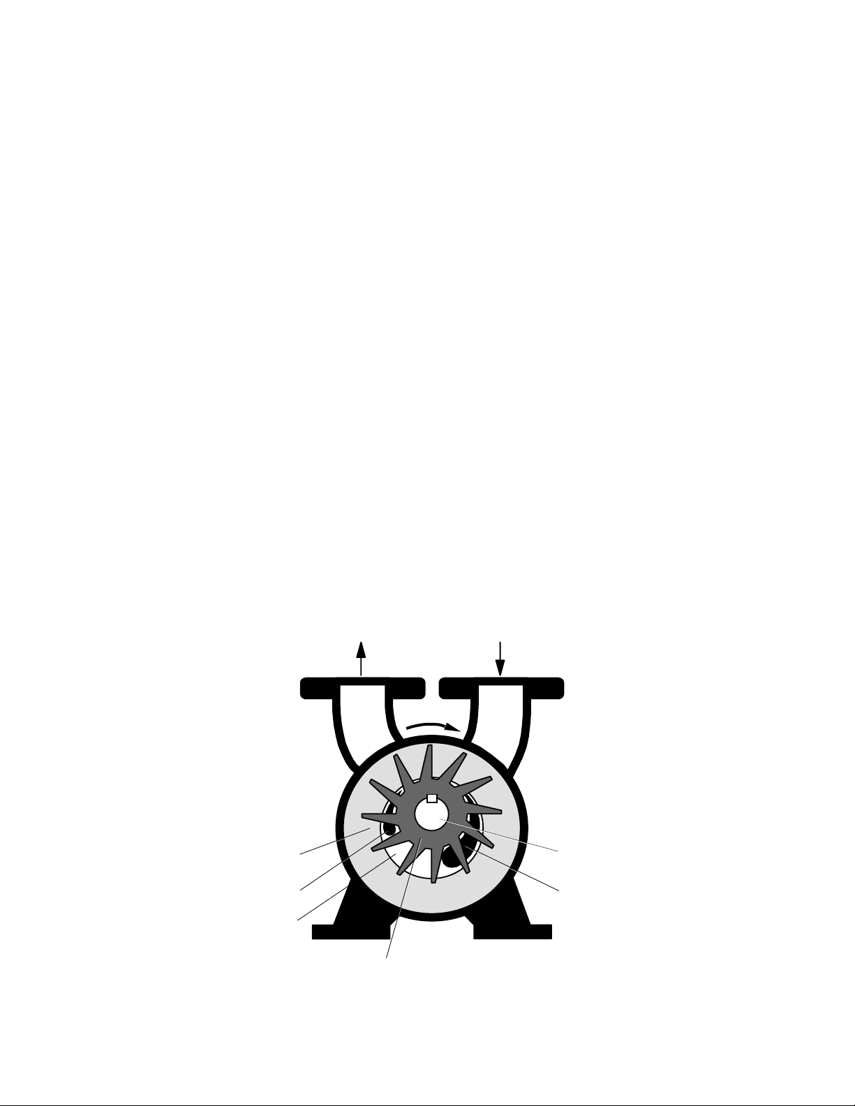
multi-bladed rotating assembly positioned eccentrically in a cylindrical casing. (See Figure 1)
This assembly is driven by an external source, normally an electric motor. Service liquid
(usually water) is introduced into the pump. As the impeller rotates, centrifugal force creates a
liquid ring which is concentric to the casing. At the inlet, the area between the impeller blades
(buckets) increases in size, drawing gas in. As the impeller continues to rotate toward the
discharge, the impeller bucket area decreases in size, compressing the gas. This gas, along with
the liquid from the pump, is discharged through the outlet nozzle. The service liquid is separated
from the gas and cooled for reuse in the pump or sent to a drain. In addition to being the
compressing medium, the liquid ring performs two other important functions:
1) It absorbs the heat generated by compression, friction, and condensation of
the incoming vapor.
2) It absorbs and washes out any process contaminants entrained in the gas.
A continuous supply of service liquid is necessary to limit the temperature rise in the pump
caused by the heat of compression, friction, and condensation. Any excessive rise in
temperature will have a detrimental effect on performance, reducing the capacity and degree of
vacuum attainable. Installation schematics for the supply of the service liquid and for the
separation of the gas and liquid discharged from the pump are shown in Section 2.
Liquid Ring
Discharge Port
Gas
Gas and
Liquid Outlet
Impeller
Gas
Inlet
Rotation
Shaft
Suction Port
FIGURE 1
4
Graham Corporation
C
ode
Service liquid quantities are a function of the particular model and the intended application.
Check the data sheet for your specific pump model or see Table 1 of Section 3 which lists typical
service liquid requirements for Graham Model Pumps.
The normal operating ranges of Liquid Ring Pumps when using water at 59 ºF
(15 ºC) for the service liquid are:
Single Stage Pumps dependent on model, down to 25 mmHgA
Two Stage Pumps down to 25 mmHgA
Two Stage Pumps w/Air Ejector down to 3 mmHgA
Single Stage Compressors 20 psi (1.4 bar) max. differential
Two Stage Compressors 30 psi (2.1 bar) max. differential
The standard materials of construction are suitable for handling air and other non-corrosive
gases, while using water as the service liquid. Other materials can be supplied for special
applications.
1.3 Description of Pump Model Codes
Each pump is designated by a model code which describes the materials of construction, size,
type of shaft seals, and any special features. An example of a typical pump is shown below.
Note: Graham Pump Models LXP30 & LXP55 are replacements for models 2PV31020 and
2PV31040 respectively.
Number of Stages
Frame Size
Series 2 Design
2 PV 42120 / 10 / DD / L
Material
Size
C-faced mounting option
(not available on all models)
Design Code Vacuum Pump = PV
5

Graham Corporation
Section 2 - Installation Instructions
2.1 Handling
Carefully unpack the pump. Bare pumps may be lifted with a sling placed around the bearing
housings or under the flanges.
Lift pump-motor assemblies by the baseplate only. Do not attach slings or hooks to the motor or
the pump as this can cause misalignment. Do not attempt to run the pump until the installation
work is complete.
CAUTION: DO NOT RUN THE PUMP WITHOUT SERVICE LIQUID AND SHAFT
SEAL FLUID.
2.2 Preservation
Cast Iron and Steel pumps are protected internally with a preservative solution applied at the
factory before shipping. The preservative solution should be flushed from the pump prior to use.
An MSDS form is included in the back of this manual (Appendix A).
The preservative solution is petroleum based and must be disposed of
in accordance with all Local, State, and Federal regulations.
2.3 Mounting
Before operation, the pump package should be carefully set, leveled, and securely bolted in
place. It is recommended that shims and grout be used as necessary under all structural members
of the base.
Graham vacuum pumps supplied with an adapter for mounting a NEMA C-faced motor should
be bolted to a floor, a cement pad or an existing framework. Support bracket located under
motor lantern should contact but not be anchored to the floor or mounting base.
Baseplates supplied with a pump and drive motor mounted at the factory should be leveled,
shimmed as required, and firmly anchored.
2.4 Installation
All piping to the pump should be adequately supported to eliminate any stress at the pump
connections. All piping joints should be tested for leaks prior to start-up. A temporary start-up
strainer in the process inlet piping may be used to keep large contaminates from entering the
pump at start-up.
6
Graham Corporation
Install the piping for the service liquid and process, as required. Refer to Section 2.7 for details.
The location of the installation or the storage of the pump should be in an area that will
not subject the pump to freezing.
Verify the pump’s rotation direction by checking the arrow on the shaft end casing. Refer to
Section 2.10 concerning the electrical requirements.
2.5 Coupling Alignment
CAUTION: TO PREVENT PERSONAL INJURY, DO NOT OPERATE THE PUMP
WITHOUT PROPERLY GUARDING THE DRIVE COUPLING(S).
Pumps supplied from the factory packaged with a motor on a baseplate have had the shafts
aligned prior to shipment. This ensures that alignment can be done in the field. It is required
that the shaft alignment be rechecked after mounting on a level foundation and prior to start-up.
When a gear reducer is supplied between the pump and motor, they are aligned at the factory and
must be realigned after installation. The gear reducer should be aligned to the pump first and
then the motor should be aligned to the gear reducer.
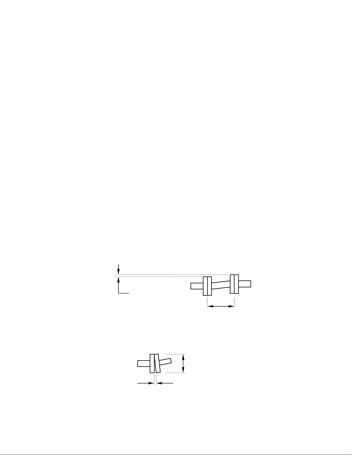
For smoother operation and longer life of the coupled equipment, the following maximum
misalignment tolerances are recommended:
The maximum allowable parallel shaft misalignment for standard couplings is ±0.002" (0.05
mm) and for spacer couplings is ±0.001" per inch (0.025 per mm) of spacer length.
The maximum allowable angular shaft misalignment is ±0.0005" per inch
(0.013 per mm) of coupling diameter.
Pumps provided with a C-faced mounted motor do not require alignment, however, the coupling
should be checked prior to start-up.
±0.002" or
±0.001" x L
L
D
±0.0005" x D
7

Graham Corporation
2.6 Belt Drives
CAUTION:
When pumps are supplied with belt drives, follow the belt manufacturer’s instructions to set the
tension.
TO PREVENT PERSONAL INJURY, DO NOT OPERATE THE PUMP
WITHOUT PROPERLY GUARDING THE DRIVE BELTS.
2.7 Service Liquid Piping Arrangements
The operating principle of a liquid ring pump depends on a continuous supply of clean service
liquid, which is normally water. The liquid enters the pump through a connection on the casing
and is discharged from the pump along with the gas. There are two basic piping arrangements
that can be used for liquid ring pump applications. A once-through method with no recovery of
the service liquid and a recirculation method which re-uses the service liquid.
Both of these arrangements have four basic elements:
1) A supply of service liquid.
2) A means to control flow of service liquid.
3) A means of stopping the flow of service liquid when the pump is off.
4) A means of separating the gas / liquid exhaust mixture.
It is recommended to use a strainer to ensure that foreign matter does not enter the pump with
the service liquid supply or make-up source. See Diagrams 1 and 2 for the proper piping
arrangement scheme.
CAUTION: COMPLETE ALL PIPING INSTALLATION AND MAKE SURE A
SUPPLY OF SERVICE LIQUID IS AVAILABLE BEFORE
STARTING THE PUMP.
8
Graham Corporation
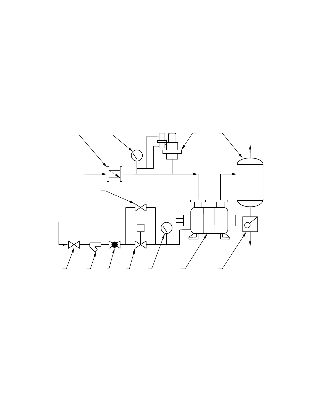
A) Typical Installation of Once Through with No Recovery
The service liquid is piped directly from a supply source to the pump. The liquid is separated
from the gas in the separator and discharged to a drain. No recirculation nor recovery takes
place. This is the most basic arrangement and can be used when service liquid conservation or
contamination is not a concern. A solenoid operated valve provides for flow of the liquid
simultaneously with the pump/motor operation. When the motor stops, the valve closes to
prevent the pump casing from filling with fluid. The by-pass valve is used to pre-fill the pump at
initial start-up only. It also can be used should the solenoid fail. When a manual valve is used, it
must be opened immediately after starting the motor and closed immediately before turning the
motor off.
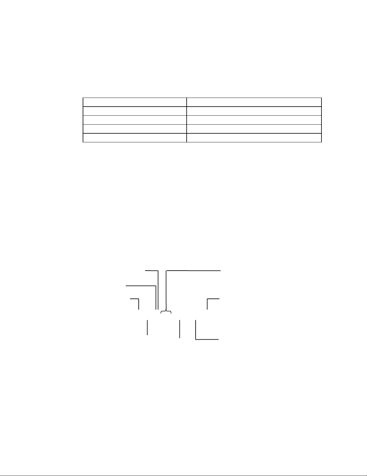
A
B
C
D
Gas
Outlet
Process
Inlet
E
Service
Liquid Inlet
S
F G H
J K
Liquid
Drain
M L
A. Inlet Check Valve G. Strainer
B. Pressure Gauge (vacuum gauge for
vacuum service or compound gauge for
compressor service)
C.
Vacuum Relief Valve (not required for
compressor service)
D.
Discharge Separator
H.
J.
K.
L.
M.
Regulating Valve
Solenoid Valve
Compound Gauge
Liquid Ring Pump
Trap (required if discharge pressure
is above atmospheric pressure)
E. By-Pass Valve
F. Shut-off Valve
ONCE THROUGH WITH NO RECOVERY
IAGRAM 1
D
9
Graham Corporation
K
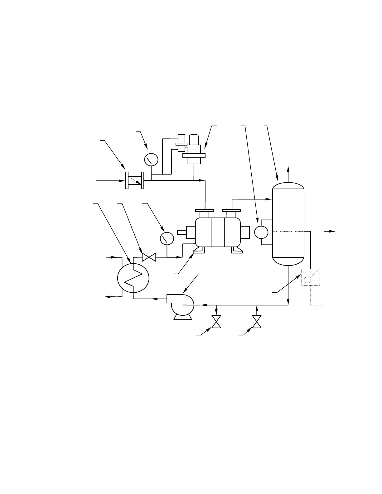
B) Typical Installation of Closed Loop with Total Recovery
This arrangement provides for the total recirculation of the service liquid. A heat exchanger is
added to the system to remove the heat of compression, friction, and condensation from the
service liquid before it is re-introduced to the pump.
The service liquid level in the separator of a total recovery system should be at, or slightly
below, the centerline of the pump shaft. A provision should be made for a high level overflow.
This will prevent starting the pump while it is full of liquid, which will damage the pump or
overload the motor.
A
B
DC
E
Process
Inlet
Gas
Outlet
F
H G
LG
Cooling
Liquid Inlet
J
Cooling
Liquid
L
Overflow
Make-up Drain
M N
A. Inlet Check Valve G. Shut-off or Throttling Valve
B. Pressure Gauge (vacuum gauge for
vacuum service or compound
gauge for compressor service)
C.
Vacuum Relief Valve (not required
for compressor service)
D.
Level Gauge
H.
J.
K.
L.
Compound Gauge
Liquid Ring Pump
Recirculation Pump (if required)
Trap or Loop Seal (required if discharge pressure is above atmospheric
pressure)
E. Discharge Separator M. Drain Valve
F. Service Liquid Cooler N. Make-Up Valve
LOSED LOOP-TOTAL RECOVERY
C
IAGRAM 2
D
10
 Loading...