

Graham PV31120, PV31040, PV31080, PV41160, PV51120 Installation, Operation & Maintenance Manual
...Page 1

Liquid Ring Pump
IOM-LRP1,2_0402
Series 1 and 2 Design
INSTALLATION, OPERATION & MAINTENANCE MANUAL
Graham Corporation ● 20 Florence Avenue ● Batavia, New York 14020
Email: equipment@graham-mfg.com ● www.graham.mfg.com
Phone: 585-343-2216 ● Fax: 585-343-1097
Page 2

Graham Corporation
Table of Contents
Section 1 - General Information...........................................................................3
1.1 Introduction....................................................................................................................... 3
1.2 General Description and Principle of Operation ........................................................... 4
1.3 Description of Pump Model Codes ..................................................................................5
Section 2 - Installation Instructions .....................................................................6
2.1 Handling............................................................................................................................. 6
2.2 Preservation....................................................................................................................... 6
2.3 Mounting............................................................................................................................ 6
2.4 Installation ......................................................................................................................... 6
2.5 Coupling Alignment..........................................................................................................7
2.6 Belt Drives.......................................................................................................................... 8
2.7 Service Liquid Piping Arrangements.............................................................................. 8
2.8 Shaft Seal Coolant Piping Arrangement....................................................................... 11
2.9 Piping Requirements....................................................................................................... 14
2.10 Electrical Requirements ............................................................................................... 14
Section 3 - Operating Instructions .....................................................................15
3.1 Start-up Procedures........................................................................................................ 15
3.2 Pump Packing Adjustment ............................................................................................15
3.3 Service Liquid Requirements......................................................................................... 16
3.4 Cavitation......................................................................................................................... 17
3.5 Shut-Down Procedures ...................................................................................................17
Section 4 - Accessory Items .................................................................................18
4.1 Accessories ....................................................................................................................... 18
Section 5 - Maintenance ......................................................................................20
5.1 Performance ....................................................................................................................20
5.2 Series 1 and 2 Pump Estimated Weights ( lbs.)*.......................................................... 20
5.3 Shaft Bearings .................................................................................................................21
5.4 Gland Packings................................................................................................................ 21
5.5 Mechanical Seals ............................................................................................................. 22
5.6 Storage.............................................................................................................................. 22
5.7 Removal from storage..................................................................................................... 23
5.8 Troubleshooting Chart ...................................................................................................24
Section 6 - Disassembly And Reassembly Procedures .....................................25
6.1 General............................................................................................................................. 25
6.2 Impeller End Clearances ................................................................................................25
6.3 Tie Rod Torque Values................................................................................................... 27
6.4 Bearing Data.................................................................................................................... 27
Section 7 - Warranty............................................................................................28
Appendix A- MATERIAL SAFETY DATA SHEET .......................................29
Appendix B- RETURN MATERIAL AUTHORIZATION FORM................33
2
Page 3

Graham Corporation
Section 1 - General Information
1.1 Introduction
This manual will provide assistance in the installation, operation, and maintenance of your
Graham Liquid Ring Pump. Please read this manual completely prior to operating your Liquid
Ring Pump. If you need to contact the Pump Service department for assistance, please have
available the pump serial number, model number, and ID number if possible. The ID number is
stamped on the edge of the discharge flange. The Pump Service department may be reached by
contacting Graham Corporation in Batavia, NY by phone (585) 343-2216, Fax (585) 343-1097,
or e-mail at
Graham has an extensive stock of spare parts and replacement pumps. Stocked parts and pumps
can be shipped from our warehouse in Batavia, NY by a carrier of your choice.
For your convenience, use our toll free number ( 1-800-828-8150 ) only when ordering spare
parts and replacement pumps. Please have the model number, serial number and part number of
the items required when placing an order. Normal business hours are 8:00 a.m. to 5:00 p.m.
(E.S.T.), Monday through Friday.
Factory rebuilding service is available for pumps returned to Batavia. When a pump is returned
to the factory for repairs, please drain and flush the pump and include a Material Safety Data
Sheet (MSDS) (see Appendix A) for the process in which the pump was used. A Return
Material Authorization (RMA) Number (see Appendix B), issued by Graham, is required
before returning a pump. A sample form is included at the back of this manual to show what
type of information is required to obtain an RMA Number. Field Service Technicians are also
available for travel to the jobsite for troubleshooting and repair or rebuilding of pumps.
This document and the information contained herein are the property of Graham Corporation
and must not be copied, in whole or in part, nor used for manufacture or otherwise disclosed
without the prior written consent of the company. Information contained herein may, from time
to time, be revised and/or updated. Copyright Graham Corporation 1999
equipment@graham-mfg.com
.
3
Page 4
Graham Corporation
1.2 General Description and Principle of Operation
Graham Vacuum Pumps and Compressors are of the liquid ring type. Single and two stage
pumps are available in a wide range of sizes and materials. These options are listed in the
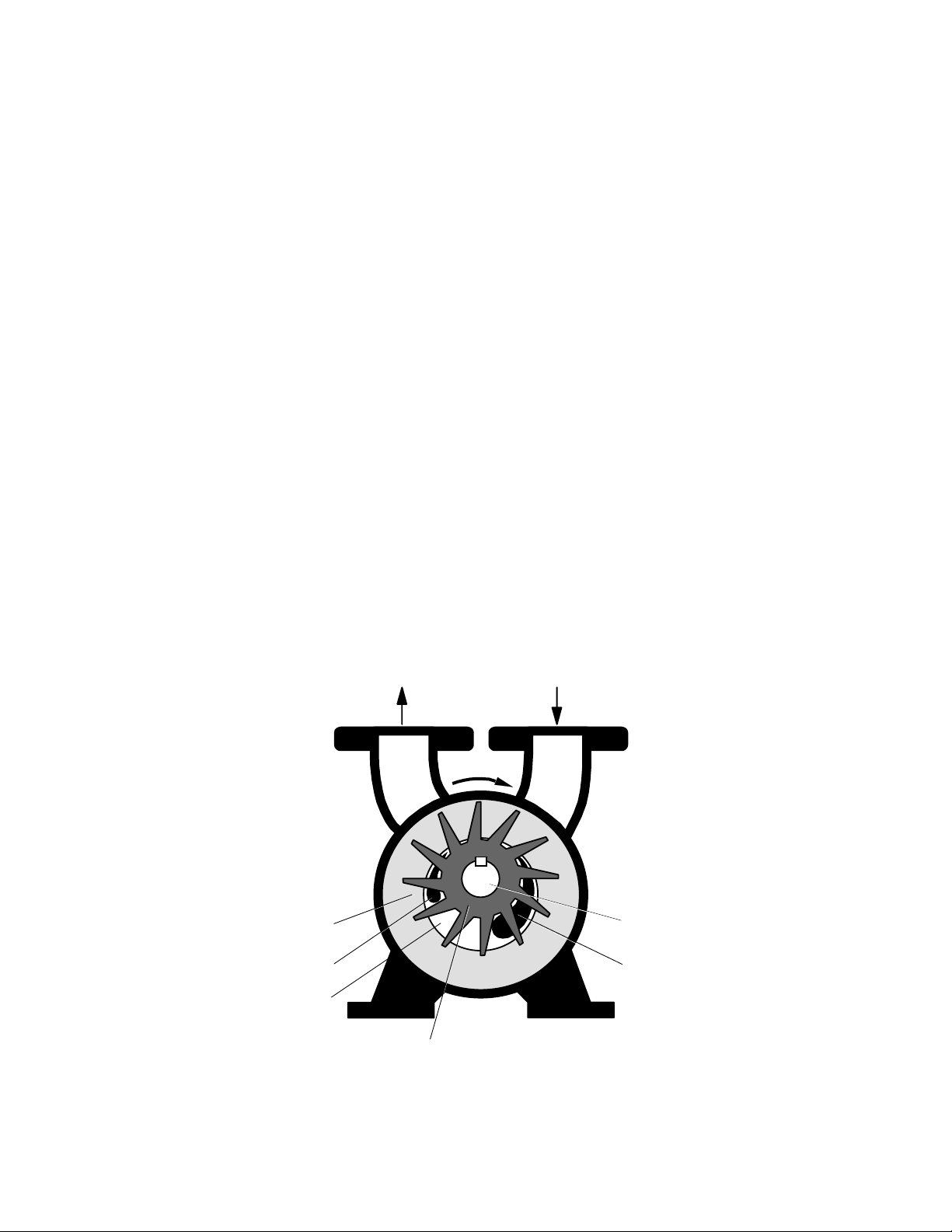
Graham Sales Bulletins. The major component of the Graham pump is a multi-bladed rotating
assembly positioned eccentrically in a cylindrical casing. (See Figure 1) This assembly is
driven by an external source, normally an electric motor. Service liquid (usually water) is
introduced into the pump. As the impeller rotates, centrifugal force creates a liquid ring which
is concentric to the casing. At the inlet, the area between the impeller blades (buckets) increase
in size, drawing gas in. As the impeller continues to rotate toward the discharge, the impeller
bucket area decreases in size, compressing the gas. This gas, along with the liquid from the
pump, is discharged through the outlet nozzle. The service liquid is separated from the gas and
cooled for reuse in the pump or sent to a drain. In addition to being the compressing medium,
the liquid ring performs two other important functions:
1) It absorbs the heat generated by compression, friction, and condensation of
the incoming vapor.
2) It absorbs and washes out any process contaminants entrained in the gas.
A continuous supply of service liquid is necessary to limit the temperature rise in the pump
caused by the heat of compression, friction, and condensation. Any excessive rise in
temperature will have a detrimental effect on performance, reducing the capacity and degree of
vacuum attainable. Installation schematics for the supply of the service liquid and for the
separation of the gas and liquid discharged from the pump are shown in Section 2.
Gas and
Liquid Outlet
Gas
Inlet
Rotation
Liquid Ring
Shaft
Discharge Port
Suction Port
Gas
Impeller
Figure 1
4
Page 5
Graham Corporation
Service liquid quantities are a function of the particular model and the intended application.
Check the data sheet for your specific pump model or see Table 1 of Section 3 which lists
typical service liquid requirements.
The normal operating ranges of Liquid Ring Pumps when using water at 59º F
(15 ºC) for the service liquid are:
Single Stage Pumps down to 150 mmHgA
Two Stage Pumps down to 25 mmHgA
Two Stage Pumps w/Air Ejector down to 3 mmHgA
Single Stage Compressors 20 psi (1.4 bar) max. differential
Two Stage Compressors 30 psi (2.1 bar) max. differential
The standard materials of construction are suitable for handling air and other non-corrosive
gases, while using water as the service liquid. Other materials can be supplied for special
applications.
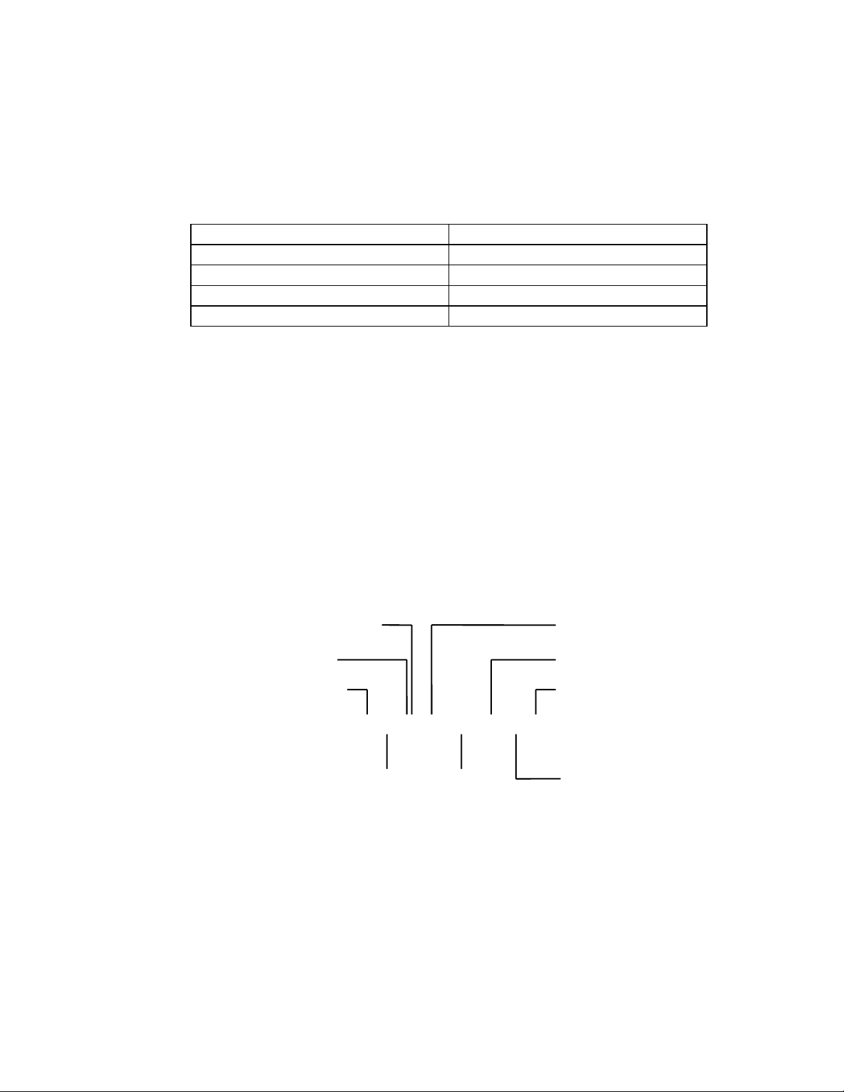
1.3 Description of Pump Model Codes
Each pump is designated by a model code which describes the materials of construction, size,
type of shaft seals, and any special features. An example of a typical pump is shown below.
Contact Graham for a complete listing of the codes used to describe the pump.
Number of Stages
Impeller Size
Frame Size
Pump Series
Shaft Seal Code
Special Features
2 PV 42120 / 12 / 43 / I / D
Vacuum Pump = PV
Compressor = PC
Pump
Material
Code
Connection
and Shaft
End Type
5
Page 6

Graham Corporation
Section 2 - Installation Instructions
2.1 Handling
Carefully unpack the pump. Bare pumps may be lifted with a sling placed around the bearing
housings or under the flanges.
Lift pump-motor assemblies by the baseplate only. Do not attach slings nor hooks to the motor
or the pump as this can cause misalignment. Do not attempt to run the pump until the
installation work is complete.
CAUTION: DO NOT RUN THE PUMP WITHOUT SERVICE LIQUID AND SHAFT
SEAL FLUID.
2.2 Preservation
Cast Iron and Steel pumps are protected internally with a preservative solution applied at the
factory before shipping. The solution should be flushed from the pump prior to use. An MSDS
form is included in the back of this manual (see Appendix A).
The preservative solution is petroleum based and must be disposed of
in accordance with all Local, State, and Federal regulations.
2.3 Mounting
Before operation, the pump package should be carefully set, leveled, and securely bolted in
place. It is recommended that shims and grout be used as necessary under all structural
members of the base.
Graham size 30000 through 50000 vacuum pump assemblies are available with an adapter for
mounting a “C-Face” motor. The pump and support bracket should be bolted to the floor, a
cement pad, or an existing framework.
Baseplates supplied with a pump and drive motor mounted at the factory should be leveled,
shimmed as required, and firmly anchored.
2.4 Installation
All piping to the pump should be adequately supported to eliminate any stress at the pump
connections. All piping joints should be tested for leaks prior to start-up. A temporary start-up
strainer in the process inlet piping may be used to keep large contaminates from entering the
pump at start-up.
6
Page 7
Graham Corporation
Install the piping for the shaft seal coolant as required. Refer to section 2.8 regarding the shaft
seal coolant piping requirements.
The location of the installation or the storage of the pump should be in an area that will
not subject the pump to freezing.
Verify the pump’s rotation direction by checking the arrow on the shaft end casing. Refer to
section 2.10 concerning the electrical requirements.
2.5 Coupling Alignment
CAUTION:
Pumps supplied from the factory packaged with a motor have had the shafts aligned prior to
shipment. This ensures that alignment can be done in the field. It is required that the shaft
alignment be rechecked after mounting on a level foundation and prior to start-up.
When a gear reducer is supplied between the pump and motor, they are aligned at the factory
and must be realigned after installation. The gear reducer should be aligned to the pump first
and then the motor should be aligned to the gear reducer.
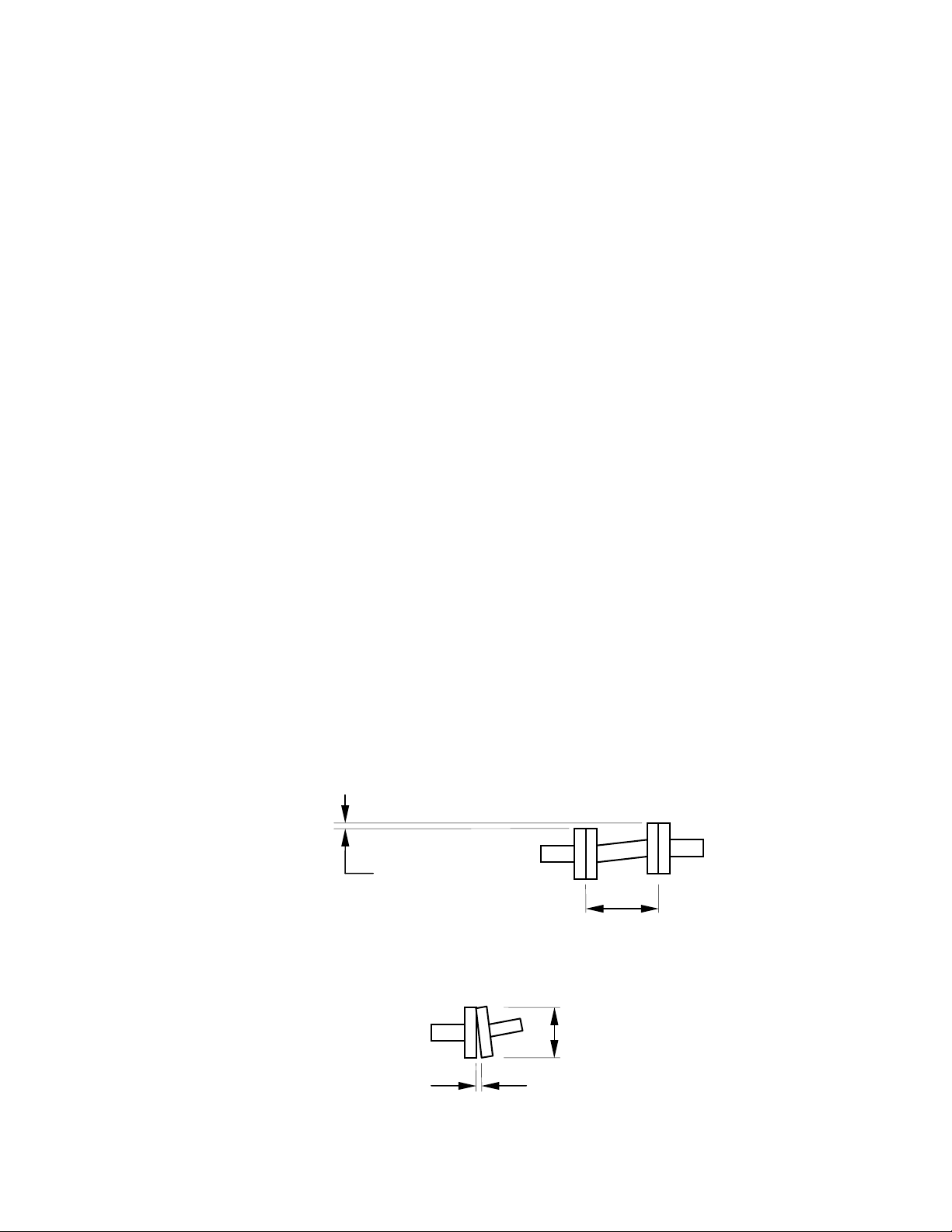
For smoother operation and longer life of the coupled equipment, the following maximum
misalignment tolerances are recommended:
The maximum allowable parallel shaft misalignment for standard couplings is
±0.002" (0.05 mm) and for spacer couplings is ±0.001" per inch (0.025 per mm) of
spacer length.
The maximum allowable angular shaft misalignment is ±0.0005" per inch
(0.013 per mm) of coupling diameter.
TO PREVENT PERSONAL INJURY, DO NOT OPERATE THE PUMP
WITHOUT PROPERLY GUARDING THE DRIVE COUPLING(S).
±0.002" or
±0.001" x L
L
D
±0.0005" x D
7
Page 8

Graham Corporation
2.6 Belt Drives
CAUTION:
When pumps are supplied with belt drives, follow the belt manufacturer’s instructions to set the
tension.
TO PREVENT PERSONAL INJURY, DO NOT OPERATE THE
PUMP WITHOUT PROPERLY GUARDING THE DRIVE BELTS.
2.7 Service Liquid Piping Arrangements
The operating principle of a liquid ring pump depends on a continuous supply of clean service
liquid, which is normally water. The liquid enters the pump through a connection on the casing
and is discharged from the pump along with the gas. There are two basic piping arrangements
that can be used for liquid ring pump applications. A once-through method with no recovery of
the service liquid and a recirculation method which re-uses the service liquid.
Both of these arrangements have four basic elements:
1) A supply of service liquid.
2) A means to control flow of service liquid.
3) A means of stopping the flow of service liquid when the pump is off.
4) A means of separating the gas / liquid exhaust mixture.
It is recommended to use a strainer to ensure that foreign matter does not enter the pump with
the service liquid supply or make-up source. See Diagrams 1 and 2 for the proper piping
arrangement scheme.
CAUTION: COMPLETE ALL PIPING INSTALLATION AND MAKE SURE A
SUPPLY OF SERVICE LIQUID IS AVAILABLE BEFORE
STARTING THE PUMP.
8
Page 9
Graham Corporation
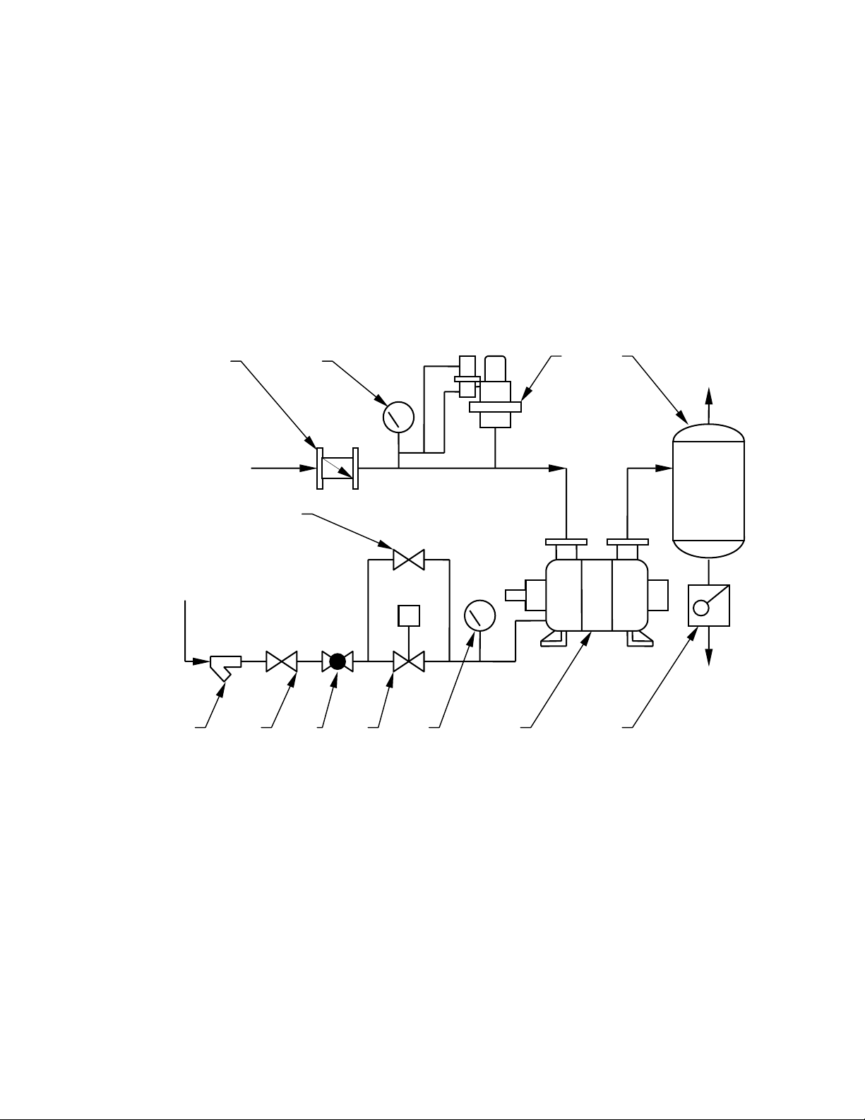
A) Typical Installation of Once Through with No Recovery
The service liquid is piped directly from a supply source to the pump. The liquid is separated
from the gas in the separator and discharged to a drain. No recirculation nor recovery takes
place. This is the most basic arrangement and can be used when service liquid conservation or
contamination is not a concern. A solenoid operated valve provides for flow of the liquid
simultaneously with the pump/motor operation. When the motor stops, the valve closes to
prevent the pump casing from filling with fluid. The by-pass valve is used to pre-fill the pump
at initial start-up only. It also can be used should the solenoid fail. When a manual valve is
used, it must be opened immediately after starting the motor and closed immediately before
turning the motor off.
D
A
B
C
Gas
Outlet
Process
Inlet
E
Service
Liquid Inlet
S
Liquid
Drain
F G H
J K
L
M
A- Inlet Check Valve G- Shut-off Valve
B- Pressure Gauge
service or compound gauge for compressor
service)
Vacuum Relief Valve
C-
compressor service)
Separator
D-
(vacuum gauge for vacuum
(not required for
H-
L-
Regulating Valve
Solenoid Valve
J-
Compound Gauge
K-
Liquid Ring Pump
M-
Trap
(required if discharge pressure
is above atmospheric pressure)
E- By-Pass Valve
F- Strainer
Once Through with No Recovery
Diagram 1
9
Page 10
Graham Corporation
N
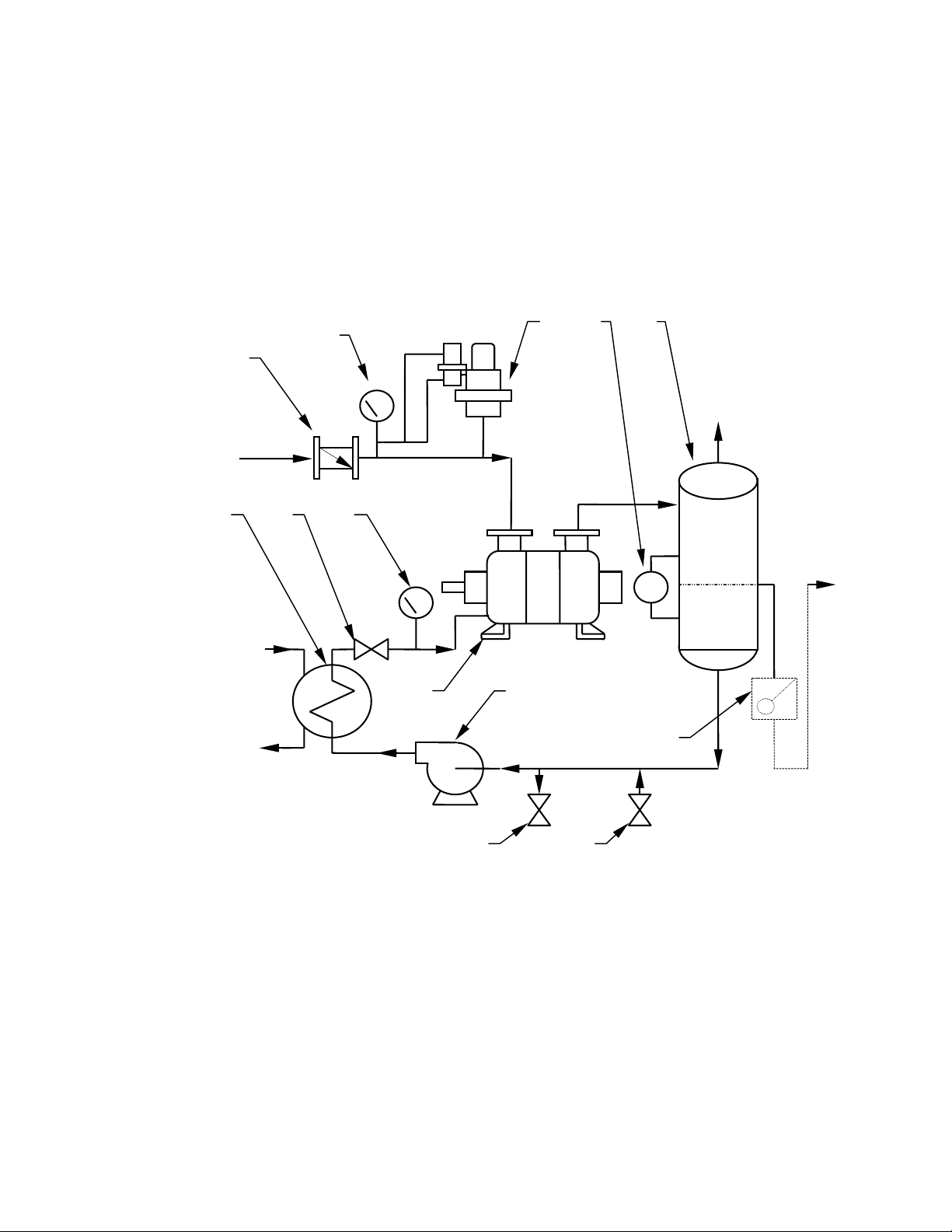
B) Typical Installation of Closed Loop with Total Recovery
This arrangement provides for the total recirculation of the service liquid. A heat exchanger is
added to the system to remove the heat of compression, friction, and condensation from the
service liquid before it is re-introduced to the pump.
The service liquid level in the separator of a total recovery system should be at or slightly
below the centerline of the pump shaft. A provision should be made for a high level overflow.
This will prevent starting the pump while it is full of liquid, which will damage the pump or
overload the motor.
D
A
B
C
E
Process
Inlet
Gas
Outlet
F
G H
LG
Cooling
Liquid Inlet
J
K
Cooling
Liquid
Drain Make-up
L
Overflow
M
A- Inlet Check Valve G- Shut-off or Throttling Valve
B- Pressure Gauge
service or compound gauge for compressor
service)
Vacuum Relief Valve
C-
compressor service)
Level Gauge
D-
(vacuum gauge for vacuum
(not required for
H-
L-
Compound Gauge
Liquid Ring Pump
J-
Recirculation Pump (recommended)
K-
Trap or Loop Seal
charge pressure is above atmospheric
pressure)
(required if dis-
E- Separator M- Drain Valve
F- Service Liquid Cooler N- Make-Up Valve
Closed Loop-Total Recovery
Diagram 2
10
Page 11

Graham Corporation
C) Draining Before Start-Up
CAUTION: DO NOT START THE PUMP WITH THE CASING FULL OF LIQUID.
A Liquid Ring Pump should not be started with the casing full of liquid. Damage to the
impeller(s) or the shaft will result. The normal liquid level should be no higher than the shaft
centerline. The pump may be started with a low liquid level as long as a supply of service
liquid is available immediately after start-up.
2.8 Shaft Seal Coolant Piping Arrangement
A) Series 1 Design
Refer to the Operating Instructions in Section 3 for guidance on running the system.
The Series 1 design incorporates a packed gland shaft sealing arrangement. On size 30000
pumps, the packings are cooled and lubricated internally therefore no piping is required. On
pumps size 40000 and larger, the glands are fitted with lantern rings and have separate
connections for the fluid. A clean source of fluid should be provided at 5 to 10 PSI (0.3 to 0.7
bar) above the discharge pressure. The discharge from the second gland can be piped to a
separator or a drain. (See Fig. 2)
Note that some Series 1 pumps are fitted with special mechanical seals. Refer to the seal
manufacturer’s instructions for cooling of these seals.
Pump Suction
Regulating
Valve
Shaft Seal Coolant Inlet at 7 to 10
PSI Above the Discharge Pressure
Sight Flow
Indicator
Figure 2
Regulating
Valve
Pump Discharge
Pressure
Gauge
Shaft Seal
Coolant Outlet
11
Page 12

Graham Corporation
g
g
B) Series 2 Design
The Series 2 pumps use single mechanical seals for shaft sealing. A shaft seal tubing assembly
(or harness) is normally provided to flush/cool the seals with service liquid from the liquid ring.
(See Figure 3)
Size 90000 pumps have shaft seals that are flushed internally and no harness is required.
Harness
Harness
Standard Configuration
Size 40000 through 80000 Size 30000
Figure 3
Note: If the service liquid contains contaminates, they will be forced to the outside of the liquid
ring by centrifugal force and then into the seal flush harness and mechanical seals. If there is a
concern that these contaminates may harm the mechanical seals, then each seal must be flushed
externally with 0.25 to 0.5 GPM (0.06 to 0.1 m
3
/hr) of clean, filtered liquid at 10 PSI (0.7 bar)
above the discharge pressure. To flush externally, remove the shaft seal harness and plug the
unused connection.
The size 30000 pump will require a seal coolant supply at the driven end only as the non-driven
end mechanical seal is cooled by the incoming service liquid. No drain piping is needed as both
seals drain internally. (See Figure 4)
Shut-Off
Valve
Regulating
Valve
Sight Flow
Indicator or
Rotameter
Shaft Seal Coolant
Inlet at 10 PSI Above
the Dischar
e Pressure
Pump
Figure 4 - Size 30000 Optional Configuration
Dischar
e
Pump
Suction
12
Page 13

Graham Corporation
cato
dicato
Size 40000 through size 80000 pumps will require coolant piping to both stuffing boxes.
Remove the seal flush harness and plug the unused connection(s). The optional piping
arrangement may be connected to either side of the pump. (See Figure 5)
Pump
Pump
Discharge
Sight Flow
In
Regulating
Valve
r
Shut-Off
Shaft Seal Coolant Inlet
at 10 PSI Above the
Discharge Pressure
Two Stage Pump
Shown
Sight Flow
Indi
Regulating
Valve
r
Figure 5 - Size 40000 through 80000 Optional Configuration
Size 90000 pumps are normally flushed internally. The coolant connections are at the ends
instead of at the side of the pump body. (See Figure 6) A plug has to be replaced with an M12
x 55 mm socket head cap screw at each end of the pump.
Plug
Screws
Pump
Suction
Sight Flow
Indicator
Regulating
Valve
Pump
Discharge
Two Stage Pump
Shown
Shaft Seal Coolant
Inlet at 10 PSI Above
Discharge
the
Pressure
Shut-Off
Valve
Sight Flow
Indicator
Regulating
Valve
Figure 6 - Size 90000 Optional Configuration
13
Page 14

Graham Corporation
2.9 Piping Requirements
A) Suction and Discharge Piping
The suction and discharge flanges on the pump are arranged vertically and are marked with
arrows on the pump casing. The suction and discharge piping should be the same nominal size as
the pump flanges. The elevation of the discharge separator above the discharge flange should be
limited to an elbow turning horizontally.
If necessary, a discharge leg can be used with a maximum of 24 inches (610 mm) above the
pump discharge flange. Too high an elevation in this line will cause excessive backpressure on
the pump, overload the motor, and reduce the pump capacity.
Remove the protective coverings from the pump openings just before attaching the piping.
Check that all foreign matter such as weld slag, nuts, bolts, rags, and dirt has been cleaned out of
the piping before connecting to the pump. The piping flanges must fit easily and without strain
on the pump flanges and the flange bolt holes must be in alignment. The flange gaskets must not
protrude into the bore of the piping or pump flanges. All piping must be supported
independently on each side of the pump without transmitting any strain to the pump casing. A
temporary suction strainer fitted at the suction inlet is recommended during the first 100 hours
of operation.
B) Service Liquid Piping
In a once-through arrangement, the nominal pipe size should be the same size as the service
liquid connection. In a total recirculation package with no recirculation pump, use one nominal
pipe size larger than the service liquid connection of the pump. Also, use the least number of
fittings to minimize the pressure drop. When a recirculation pump is used, the piping should be
the same size as the service liquid connection.
2.10 Electrical Requirements
All electrical wiring and installation must comply with local safety codes.
After the electrical work is complete, the motor should be jogged to check for proper rotation.
First, turn the pump by hand to see that it rotates freely. On Series 1 pumps, it may be
necessary to loosen the gland packing rings (see Section 3.2) to allow the shaft to turn easily.
The direction of rotation is marked on the pump. Second, jog the motor momentarily to check
the rotation. It is recommended to use a non-reversing motor controller to prevent the pump
from turning in the wrong direction.
14
Page 15

Graham Corporation
Section 3 - Operating Instructions
3.1 Start-up Procedures
Read all instructions before proceeding.
1) Turn the shaft manually to ensure it rotates freely. If the pump is binding or seized,
refer to the troubleshooting chart in Section 5.
2) Fill the pump with service fluid to the shaft centerline, but do not overfill
CAUTION : DO NOT RUN THE PUMP WITHOUT SERVICE LIQUID
AND SHAFT SEAL FLUID.
3) The normal service liquid level should be no higher than the shaft centerline. The
pump may be started with a low service liquid level as long as a supply is available
immediately after start-up.
4) Open any valves in the suction and discharge lines.
5) Confirm the pump rotation with the arrow on the casing by jogging the motor.
6) Start the motor, ensure service liquid supply, and set regulating valve, when used,
for optimum pump performance. Open and adjust the shaft seal cooling liquid
valve, when used.
3.2 Pump Packing Adjustment
On Series 1 pumps, the packing adjustment nuts should be loosened before running to prevent
damage to the shaft. With the gland follower loosened, the liquid pressure in the glands will
force the packing rings against the gland follower. The pump can be run for several hours in
this manner. Tighten the gland follower to allow the cooling fluid to drip from the gland at a
rate of about 20 drops per minute from each end while the pump is running at a steady state.
Gland Packing
One end of pump shown
Packing Adjustment Nuts
Pump Shaft
Gland Follower
15
Page 16

Graham Corporation
3.3 Service Liquid Requirements
A) Flow Rates
Service liquid flow rates depend on the type of piping arrangement used, the size and operating
speed of the pump, and the allowable temperature rise through the pump. Nominal flow rates
for standard pumps and compressors at normal conditions are given in Table 1.
Service liquid flow rates and the temperature rise are important because of their effect on pump
performance. Too little flow will result in loss of capacity. Too much flow will result in
excessive horsepower requirements.
Service Liquid Flow Rates*
Single Stage Pumps Two Stage Pumps
Pump Model
PV31040 4 PV32040 4
PV31080 4 PV32080 4
PV31120 6 PV42120 6
PV41160 6 PV42160 6
PV51080 8 PV52120 8
PV51120 8 PV52160 8
PV51160 10 PV52200 10
PV51200 11 PV62160 20
PV61255 20 PV62240 24
PV61335 25 PV72200 30
PV71300 30 PV72300 30
PV71400 30 PV72400 30
PV81360 45 PV72500 35
PV81460 50 PV82350 35
PV81560 55 PV82450 40
PV91540 100 PV82550 45
PV91670 100 PV92540 100
PV92670 100
* Flowrates apply to PV or PC design. For units in m3/hr, multiply USGPM by 0.227
USGPM
Pump Model
Table 1
B) Flow Control
If a flow device is not used to measure the service liquid quantity to the pump, a regulating
valve and compound gauge in the service liquid line can be used to approximate the flowrate.
For pump operating pressures between atmospheric and 400 mmHgA, the reading on the
compound gauge should be in the range of 2" HgV to 5 psig (709 mmHgA to 0.35 barg). For
operating pressures below 400 mmHgA, the compound gauge reading should be in the range of
15" HgV to 2 psig (379 mmHgA to 0.14 barg). This method is only an approximation of the
service liquid quantity. The actual operating conditions will dictate the amount of sealant liquid
required and also the compound gauge reading.
USGPM
16
Page 17

Graham Corporation
C) Hard Water
If hard water is used as the service liquid, scale deposits caused by the precipitation of minerals
will occur. This will vary with the temperature of the water. Scale deposits on the internal
surfaces of the pump will cause an increase of the operating horsepower, wear on moving parts,
and may cause the pump to seize. If the hardness of the water is excessive, consider using a
water softening treatment.
3.4 Cavitation
Cavitation is identified by a characteristic metallic or grinding noise inside the pump. It is
caused when the pump suction pressure is too close to the vapor pressure of the service liquid.
If the service liquid temperature inside the pump rises such that its vapor pressure closely
approaches the suction pressure of the pump, cavitation will occur.
When cavitation takes place, vapor bubbles form and collapse within the liquid ring. This will
damage the surfaces of the impeller, side plates, and casing. Cavitation causes damage by
tearing away metal particles. The damage may be more severe in a corrosive situation.
Cavitation may be prevented by bleeding air into the pump to raise the suction pressure.
Vacuum relief valves can be fitted in the suction piping for this purpose. If the pump is
provided with an air attenuation valve, it can be opened to bleed air into the second stage
casing until the noise stops.
If the problem is not caused by a low flow of non-condensable gases, the service liquid
temperature should be checked. Ultimately, the vacuum at which the pump can be operated is
governed by the vapor pressure of the service liquid inside the pump.
3.5 Shut-Down Procedures
1) Shut off the service liquid supply and if used, the shaft seal coolant, and
immediately stop the motor.
2) If necessary, close all suction and discharge valves.
3) If necessary, drain the pump to protect it from freezing by removing all drain plugs.
4) Disconnect power from the motor if maintenance is to be performed.
17
Page 18

Graham Corporation
Section 4 - Accessory Items
4.1 Accessories
There are many accessory items associated with Liquid Ring Vacuum Pumps and Compressors.
They can be supplied by Graham and shipped from the factory or can be supplied by others and
installed in the field. The particular requirements, mode of operation, and type of control
scheme desired dictate the necessity of various items. The following is a list of common
accessories.
Inlet Check Valve Used to prevent a back flow of gas into the process when the
pump is stopped. Check valves are normally installed in a
horizontal line. An elbow can be provided to adapt the vertical
pump inlet to accept a horizontal check valve.
Vacuum Relief Valve Used to protect the pump from cavitation and control the pump
suction pressure. When the pump capacity exceeds the system’s
flow requirements at a pre-determined level, the valve will
open and bleed in atmospheric air or process gas.
Flexible Connector Used to compensate for minor misalignment or expansion
between the pump connections and the process piping.
Vacuum Gauge Used to indicate vacuum at the pump inlet. Normally mounted
directly ahead of the pump suction.
Shut-off Valve Used to manually stop the flow of service liquid to the pump.
Strainer Used to filter out solid particles that will damage the pump.
Flow Regulator Used to control the service liquid flow rate to the pump.
A manual valve, a fixed orifice, or a flexible element orifice
may be used depending on the application.
Compound Gauge Used to indicate pressure in the service liquid piping.
Discharge Separator Used to separate the service liquid from the discharged gas as it
comes out of the pump. The liquid can be piped to a drain or
recovered for reuse.
Solenoid Valve Used to automatically stop or start the flow of service liquid to
the pump. Normally interlocked to the pump motor.
By-pass Valve Used to initially fill the pump with service liquid or for bypass
in case the solenoid coil fails.
Recirculation Pump Used to circulate the service liquid recovered from the
discharge separator in some total recovery systems.
18
Page 19

Graham Corporation
Heat Exchanger Used to remove heat from the recirculated service liquid.
Atmospheric Used to provide a suction pressure lower than the pump is
Air Ejector capable of when operating alone. It may be added to a two stage
pump to provide an inlet pressure as low as 3 mm HgA. The
operation of the air ejector is similar to that of a steam ejector.
Atmospheric air or recycled gas from the discharge separator is
used as the motive force for compressing the process gas from
the system design pressure up to the inlet pressure of the pump.
To enhance pumping capacity at a higher suction pressure, an
optional motive air shut-off valve or by-pass valve can be added.
(See Figure 7)
Atm os pher ic
Air Inlet
Optiona l
Shut -off
Valve
P rocess Inlet
Atm os pher ic
Air Eject or
Optiona l
By-pas s
Discharge
Liquid Ring
V acuum Pump
Typi cal Atm os phe r ic Air Eject or
Valve
Figure 7
19
Page 20

Graham Corporation
Section 5 - Maintenance
5.1 Performance
Optimum performance and long service life are dependent upon good maintenance procedures
and periodic inspections. When preparing to dismantle a pump, make provisions for the safe
handling of heavy parts.
5.2 Series 1 and 2 Pump Estimated Weights ( lbs.)*
Cast Iron
Pump Model Dry Operating Flooded Pump Model Dry Operating Flooded
PV31040 97 103 108 PV32040 139 146 152
PV31080 106 114 121 PV32080 161 171 181
PV31120 115 125 134 PV42120 214 227 234
PV41160 194 206 218 PV42160 245 262 280
PV51080 243 257 271 PV52120 342 364 386
PV51120 265 282 299 PV52160 377 403 430
PV51160 331 351 370 PV52200 397 428 459
PV51200 408 434 461 PV62160 582 622 661
PV61255 639 675 710 PV62240 613 666 719
PV61335 705 745 785 PV72200 1124 1202 1279
PV71300 1190 1268 1345 PV72300 1323 1424 1526
PV71400 1323 1407 1490 PV72400 1510 1625 1739
PV81360 3086 3186 3285 PV72500 1674 1812 1918
PV81460 3417 3549 3682 PV82350 3219 3364 3510
PV81560 3748 3902 4056 PV82450 3483 3633 3784
PV91540 4299 4475 4652 PV82550 3748 3898 4048
PV91670 4519 4694 4869 PV92540 5060 5235 5410
PV92670 5500 5675 5850
Stainless Steel, Carbon Steel, and Bronze
Pump Model Dry Operating Flooded Pump Model Dry Operating Flooded
PV31040 102 123 130 PV32040 146 175 183
PV31080 111 136 146 PV32080 169 205 217
PV31120 121 149 161 PV42120 225 272 280
PV41160 204 247 262 PV42160 257 315 336
PV51080 255 286 392 PV52120 359 437 463
PV51120 278 341 402 PV52160 396 484 516
PV51160 348 421 444 PV52200 417 513 550
PV51200 428 521 553 PV62160 611 746 794
PV61255 671 810 852 PV62240 644 799 862
PV61335 740 894 942 PV72200 1180 1442 1534
PV71300 1250 1521 1614 PV72300 1389 1709 1831
PV71400 1389 1688 1788 PV72400 1586 1950 2087
PV81360 3240 3390 3540 PV72500 1758 2137 2286
PV81460 3588 3738 3888 PV82350 3380 3530 3680
PV81560 3935 4085 4235 PV82450 3657 3807 3957
PV91540 4514 4689 4864 PV82550 3980 4085 4235
PV91670 4745 4920 5095 PV92540 5313 5488 5663
PV92670 5775 5950 6125
* Pump weights apply to PV or PC design. For units in kg, multiply lbs. by 0.454
Table 2
20
Page 21

Graham Corporation
5.3 Shaft Bearings
The size 30000, 40000, and 50000 pumps use sealed-for-life bearings that are not regreasable.
Size 60000 and larger pumps use regreasable bearings that are pre-packed at the factory. Some
grease may ooze out of the bearing housing during the break-in period. The regreasable bearings
should be lubricated after 3000 hours running time. Lithium based greases are recommended.
For Size 90000 pumps, the bearings are pre-packed at the factory, but prior to system start-up,
additional grease should be added by using the zerk fitting on each bearing cover.
Approximately 1/2 a tube may be required for each bearing as the intention is to fill each empty
cavity in the bearing cover 1/2 full of grease. If during this procedure an escape of grease is
noted around the oil seal on the inner bearing cover, the bearing has received sufficient
lubrication. Over greasing of the bearing is prevented as the grease can escape around the oil
seal as the bearing heats up during operation.
If either bearing cover is removed on the outboard end of the Size 90000 pump, care must be
taken when it is replaced. Also, the bearing cover needs to be tightened evenly. This is critical
since the position of the rotor is determined by the movement of these covers in relation to the
bearing housings on the outboard end. Axial movement of the rotor may cause it to contact the
port plate, damaging the pump at start-up.
The standard bearings are rated for an L10
life of 80,000 hours. The temperature of the bearings
h
should not exceed 140ºF (60ºC). Overheating may be due to excess grease, misalignment of the
shafts, or a bad bearing.
5.4 Gland Packings
The Series 1 pump glands are packed with square braided, graphite coated, cotton fiber packing
material. If the glands leak air into the pump or leak excessive service liquid out of the gland,
tighten the gland follower slightly. (See Section 3.2) If further tightening becomes impossible,
replace the packings.
To replace the packings, remove the gland follower and outboard packing, and then the lantern
ring. The inboard packing can then be removed using an extractor. Lantern rings are not used on
size 30000 pumps.
The new packings should be cut in individual rings. The ends should be located at staggered
positions around the shaft. The lantern ring should be placed in the gland to align with the
gland cooling fluid connection. Replace the outboard packing rings and tighten the gland
follower finger tight. Refer to Section 3.2 for the break-in procedure.
21
Page 22

Graham Corporation
5.5 Mechanical Seals
The Series 2 pumps are fitted with single acting mechanical shaft seals. They should be
replaced when worn, scratched, or cracked, or when the rotating segment no longer grips the
shaft. There is a weep hole on the underside of each bearing seal housing. If a mechanical seal
has failed, leakage will occur at this location.
Series 1 pumps may be fitted with mechanical seals when a specific type of seal will not fit into
the stuffing box of a Series 2 pump.
The Series 1 pumps are also used when double mechanical seals are required. This arrangement
is used when handling gases that are volatile, toxic, or corrosive. The shaft seal coolant is
normally circulated through the seal chamber at a pressure slightly above the pump discharge
pressure or as recommended by the mechanical seal manufacturer. This creates a barrier and
prevents the pumped gasses or liquid from escaping to the atmosphere. The barrier fluid also
dissipates heat, lubricates both sealing faces, and monitors the condition of the mechanical seals.
When replacing the mechanical seals, clean the shaft thoroughly. The seal faces must be
protected during installation from particles which may scratch the surfaces.
CAUTION:
DO NOT RUN THE PUMP WITHOUT SERVICE LIQUID AND
SHAFT SEAL FLUID.
5.6 Storage
If a pump is to be out of service, it should be protected internally from rusting by using a rust
inhibitor. The pump should be drained completely by removing all the lower plugs. Install the
plugs and fill with Oakite HPO (or equal) preservative solution. Remove the manifold(s) and
spray the insides with preservative. Rotate the pump manually to circulate the solution. Drain
the pump to below the shaft centerline and replace the manifold(s). This procedure may be
disregarded for pumps made of stainless steel, bronze, Monel, or other corrosion resistant
materials.
Seal the flanged openings to prevent foreign material from entering the pump.
The pump shaft should be rotated each week to distribute the preservative and to prevent flat
spots on the bearings. Document the time, date, and by whom this procedure was performed.
The manifold(s) should be re-sprayed monthly and the pump checked to see that the
preservative is maintained. This will protect the pump for up to twelve months.
Pumps stored at low temperatures may need to be protected from freezing either by draining
completely or by using an anti-freeze solution.
Pumps with V-belt drives should have the belts loosened to relieve the belt tension during
storage. Do not store near running electric motors as ozone produced is detrimental to the
rubber in the belts.
22
Page 23

Graham Corporation
5.7 Removal from storage
The pump should be drained and flushed if necessary to remove the preservative solution. Refer
to Section 3.1 of this manual for the recommended start-up procedure.
CAUTION:
An MSDS form is included in the back of this manual (See Appendix A).
THE OAKITE HPO PRESERVATIVE SOLUTION IS
PETROLEUM BASED AND MUST BE DISPOSED OF IN
ACCORDANCE WITH ALL LOCAL, STATE, AND FEDERAL
REGULATIONS.
23
Page 24

Graham Corporation
5.8 Troubleshooting Chart
Problem Cause Solution
Reduced
Capacity
Excessive
Noise
High Power
Consumption
Overheating
Vibration
Excessive
Gland
Leakage
Abnormal
Bearing Wear
or Failure
Shaft Will Not
Turn or
Partially
Seizes
Speed too low
•
Leak in suction line
•
Service liquid temperature too high
•
Insufficient or excess service liquid
•
Excessive back pressure
•
Excessive or insufficient service liquid
•
Shaft misalignment
•
Defective bearing
•
Cavitation
•
Back pressure
•
Excessive service liquid
•
Shaft misalignment
•
Excessive back pressure
•
Defective bearing
•
Gland follower too tight
•
Improperly mounted pump
•
High temperature process load
•
Service liquid temperature too high
•
Insufficient service liquid
•
Shaft misalignment
•
Defective bearing
•
Gland ring too tight
•
Shaft misaligned
•
Pump or baseplate not properly anchored
•
Defective bearing
•
Improperly mounted pump
•
Cavitation
•
Back pressure
•
Excessive service liquid
•
Worn packing
•
Loose gland
•
Gland coolant pressure too high
•
Shaft misalignment
•
Piping load on pump flange
•
Mechanical seal leakage
•
Shaft flinger missing
•
Scale build-up
•
Foreign object in pump
•
Piping load on pump flange
•
Improperly mounted pump
•
Soft Foot
•
Table 3
Check power supply and transmission
•
Repair
•
Check coolant flow & heat exchanger
•
Provide correct flow rate
•
Eliminate cause of back pressure
•
Adjust flow rate
•
Realign shafts
•
Replace bearing
•
Open attenuation valve or adjust vacuum
•
relief valve
Eliminate cause of back pressure
•
Reduce flow rate
•
Realign shafts
•
Eliminate cause of back pressure
•
Replace bearing
•
Loosen gland follower
•
Make sure surface is level and all feet touch
•
the surface, shim if necessary.
Check conditions upstream of pump
•
Check coolant flow & heat exchanger
•
Provide correct flow rate
•
Realign shafts
•
Replace bearing
•
Loosen gland ring, check packing coolant
•
flow
Realign shafts
•
Anchor
•
Replace bearing
•
Make sure surface is level and all feet touch
•
the surface, shim if necessary.
Open attenuation valve or adjust vacuum
•
relief valve
Eliminate cause of back pressure
•
Provide correct flow rate
•
Replace packing
•
Tighten gland follower
•
Reduce pressure
•
Realign shafts
•
Support connecting pipe work
•
Replace seals
•
Replace flinger
•
Descale pump
•
Remove foreign object
•
Support connecting pipe work
•
Make sure surface is level and all feet touch
•
the surface, shim if necessary.
Correct pump / motor mounting
•
24
Page 25

Graham Corporation
Section 6 - Disassembly And Reassembly Procedures
6.1 General
Complete disassembly of the pump is seldom necessary and it may only need to be disassembled
to the point required to repair or service it. Specific instructions are included with the
documentation sent with your liquid ring pump. The cross-section drawing and parts list should
be referred to when servicing the pump and when ordering spare parts.
Before any servicing takes place, it is recommended that a set of gaskets, bearings, and gland
packings or mechanical seals be on hand as spare parts. The stocking of additional items
beyond these basic wearing parts is dependent upon the type of application, compatibility of
pump materials with the process gas and service liquid, degree of corrosion and erosion to
which the pump is subjected, importance of pump reliability to the process, etc.
When ordering spare parts, be sure to identify the pump size, serial number, part name and
reference number, and if available, original purchase order number, Graham job number, or a
drawing number.
6.2 Impeller End Clearances
Refer to Table 4 for the impeller end clearances. These values are for each side of the impeller
in each stage. These clearances are extremely important for optimum pump performance. Also
refer to the dismantling and reassembly procedures that were provided with the documentation
sent with your pump.
Impeller End Clearances *
Pump
Frame
Size
30000 0.004"-0.006" 0.006"-0.009"
40000 0.004"-0.006" 0.006"-0.009"
50000 0.006"-0.008" 0.009"-0.012"
60000 0.008"-0.010" 0.012"-0.015"
70000 0.010"-0.014" 0.014"-0.018"
80000 0.012"-0.016" 0.016"-0.020"
90000 0.012"-0.016" 0.016"-0.020"
* For units in mm, multiply inches by 25.4
Cast Iron, Ductile Iron, Bronze,
Carbon Steel, Ni-Alum.-Bronze
Construction
Table 4
Stain. Stl., Titanium, Alloy 20
Monel, Hastelloy
Construction
25
Page 26

Graham Corporation
A) Gasketed Pumps
The critical impeller end clearance locations and typical gasket locations are shown in Figures 8
and 9. The gaskets between the impeller casings and the end plates determine the impeller end
clearances. Check and record the thickness and quantity of these gaskets at each joint when
dismantling. The gaskets may be held in place with grease during re-assembly. The gasket
thicknesses used on pumps of standard materials of construction are 0.008" to 0.010" (0.2 to
0.25 mm). The gasket thicknesses used on high alloy pumps are 0.015" to 0.018" (0.38 to 0.46
mm).
Do not use joint sealing compound to replace a gasket as the clearances in the pump will be
affected.
Gaskets
Se ries 1
*
* Impeller clearance locations.
Gaskets
*
Gaskets
Single Stage
Figur e 8
*
*
Gasket for two pi ece
inter st age casi ng de s ign
Two Stage
Figu r e 9
Se ries 2
*
Se ries 2 Only
Both Ends
Gaskets
Gaskets
Se ries 1
Se ries 2
*
Se ries 2 Only
Both Ends
Gaskets
26
Page 27

Graham Corporation
B) Non-Gasketed Pumps
Size 30000, 40000, and 50000 Cast Iron pumps do not require gaskets, but use a joint sealing
compound between the impeller casings and the end plates. They are machined to accommodate
the same impeller end clearances as a gasketed pump.
6.3 Tie Rod Torque Values
Table 5 includes torque values for re-assembling the pumps.
Pump Frame
Tie Rod Torque *
Size
30000 40 ft.-lbf
40000 40 ft.-lbf
50000 40 ft.-lbf
60000 70 ft.-lbf
70000 90 ft.-lbf
80000 250 ft.-lbf
90000 300 ft.-lbf
* For units in N-m, multiply ft-lbs by 1.355
Table 5
6.4 Bearing Data
The correct bearing fit class needs to be used in order for proper operation. Do not use a C3
fit as it is too loose and will cause damage to the pump. Table 6 provides correct bearing
data for the pumps.
Pump
Frame Size
30000 6305/2RS1 Ball Bearing, Single AFBMA 0 25 mm, +15, +2 k6
40000 6306/2RS1 Row, Deep Groove, AFBMA 0 30 mm, +15, +2 k6
50000 6308/2RS1 Double Seals (SFL) AFBMA 0 40 mm, +18, +2 k6
60000 6310 Ball Bearing, Single AFBMA 0 50 mm, +18, +2 k6
70000 6314 Row, Deep Groove AFBMA 0 70 mm, +21, +2 k6
80000 22320 CC/W33 Spherical Roller Brng. AFBMA 0 100 mm, +0, -22 h6
90000 DE 23224 CC/W33 Spherical Roller Brng. AFBMA 0 120 mm, +0, -22 h6
90000 NDE 7224 BCBM Sngl. Row Ball Brng. (2) AFBMA 0 120 mm, +0, -22 h6
SKF Bearing
Number
Type Bearing Fit
Class
(Normal Fit)
Bearing Journal
Diameter & Tolerance
Table 6
Tolerance
Class
(µm)
27
Page 28

Graham Corporation
Section 7 - Warranty
THE FOLLOWING IS IN LIEU OF ALL WARRANTIES OF GRAHAM EXPRESSED OR
IMPLIED AND ALL IMPLIED WARRANTIES, INCLUDING BUT NOT LIMITED TO ANY
IMPLIED WARRANTY OF MERCHANTABILITY OR FITNESS FOR A PARTICULAR
PURPOSE, AND/OR ANY OTHER OBLIGATION ON THE PART OF GRAHAM ARE
HEREBY EXCLUDED:
Graham, except as otherwise provided, warrants goods of its own manufacture against faulty
workmanship or the use of defective materials, under normal use and service, and that such goods
will conform to mutually agreed upon written specifications, drawings, and is guaranteed to meet
specified performance requirements, for a period of twelve (12) months from date of shipment of
the goods from the factory.
Graham assumes no responsibility for deterioration of the equipment due to corrosion, erosion,
or flow induced tube vibration, or for fouling, maintenance problems or any other causes not
specifically covered under the foregoing warranty. The sole remedy of Buyer with respect to
any part not conforming to any warranty of Graham shall be the repair or, at Graham’s option,
replacement of any defective part at the point of manufacture, Buyer assuming all costs of
removal, shipping, and reinstallation, provided that immediate written notice of the defect has
been given to Graham, and Graham shall not be liable for any other expenses incurred because
of failure of any part to meet Graham’s warranty, nor for any special, indirect or consequential
damages. Material returned to Graham’s factory without its written consent will not be
accepted. No back charges will be honored without Graham’s advance approval of the work to
be performed. Graham’s liability on any claim of any kind, including negligence, for any loss
or damage arising out of, connected with, or resulting from this transaction, or the design,
manufacture, sale, delivery, resale, installation, technical direction of installation, inspection,
repair, operation, or use of any equipment covered by or furnished hereunder shall in no case
exceed the price paid by Buyer for the equipment. Graham also disclaims all liability, whether
in contract, tort, warranty, or otherwise, to any party other than the Buyer.
In the event the pumps are altered or repaired by any person or entity other than Graham,
without written approval by Graham, all warranties are void. Bearings and shaft seals are
warranted only to the extent of, and pursuant to, the original manufacturer's warranty
28
Page 29

Graham Corporation
Appendix A- MATERIAL SAFETY DATA SHEET
29
Page 30

Graham Corporation
30
Page 31

Graham Corporation
31
Page 32

Graham Corporation
32
Page 33

Graham Corporation
Appendix B
(Note: This form not to scale)
Graham Corporation, 20 Florence Ave., Batavia, New York 14020
Tel: (585) 343-2216 FAX: (585) 345-1370 E-MAIL: equipment@graham-mfg.com
RETURN MATERIAL AUTHORIZATION FORM
- - - - - - - - - - - - - - - - - - - - - - - - - - - - - - - - - - - - -- - - - - - - - - - - - - - - - - - - - - - - - - - - - -
(This section completed by authorized Graham personnel only. Use Tab Key or Cursor to complete areas.)
TO: Date:
(Customer’s Name & Company Name)
FROM: Fax No.:
RMA Number:
(current date, auth. Graham personnel
- - - - - - - - - - - - - - - - - - - - - - - - - - - - - - - - - - - - - - - - - - - - - - - - - - - - - - - - - - - - - - - - - - - - - - - - - - - - - -
Sections A, B, & C to be completed by the customer and RETURNED VIA FAX to the Graham Service
Department. For E-mailed form, use Tab Key or Cursor to complete areas. An additional copy must also
be included with the returned equipment. No work will be started on the equipment being returned until
the Service Department has the completed form.
MSDS (Material Safety Data Sheet) must be included for all material(s) handled by the equipment. Work on
the equipment will not begin until MSDS sheets are received. This is to ensure the safety of all Graham
employees who may come in contact with this equipment.
The equipment must be cleaned, drained and DECONTAMINATED prior to shipping back to Graham.
Equipment returned in an unsatisfactory condition will be returned to the sender.
(Originator -- Auth. Graham Personnel)
initials,01, 02, etc. as applies for that date)
S A M P L E
E-Mail:
RMA Number Assigned by Authorized
Graham Batavia Personnel Only
A. Customer Data
Customer: Contact Person:
Mailing Address: Phone Number:
Fax Number:
E-Mail:
B. Graham Equipment Information
Graham Serial No.:
ASME Unit?: NO YES - Engineering Procedure EP-006 applies
Type of Equipment / Model No:
Material Handled by Equipment:
Reason for Return:
C. Authorized Customer Signature
Send equipment, RMA form and MSDS sheets to the address shown above, Attn: Service Dept.
Graham Corporation is not responsible for any freight charges.
(Units must be returned with freight prepaid or they will not be accepted.)
CC: Project Engineering Secretary – For Distribution
Prod. Control, QA, QC, Originator, Credit
33
 Loading...