

GRAF & MEYER eXentro PA-8250, eXentro PA-8125 Safety And Installation Manualline

eXentro PA-8250 / PA-8125 power amplifier
Safety and Installation Guideline
Sicherheitsrichtlinien und Installationsanleitung
Guide d’installation et de sécurité
Retningslinjer for sikkerhed og installation
Guía de seguridad e instalación
Linee guida per la sicurezza e l'installazione
Veiligheids- en installatiehandleiding
Riktlinjer för säkerhet och installation
Wytyczne dotyczące bezpieczeństwa i instalacji

The manufacturer reserves specification privileges. Information in this manual is subject to change without prior notice or obligation.
Der Hersteller behält sich das Recht vor, Änderungen im Sinne des technischen Fortschritts durchzuführen, die u.U. noch nicht in
dieser Bedienungsanleitung berücksichtigt wurden.
Producenten forbeholder sig særlige rettigheder. Oplysningerne i denne vejledning kan ændres uden forudgående varsel og uden
forpligtelser.
El fabricante se reserva los derechos de las especificaciones técnicas. La información contenida en este manual está sujeta a cambio
sin previo aviso ni obligación.
Le fabricant se réserve le droit de modifier les spécifications contenues dans ce manuel sans préavis.
Il produttore si riserva diritti di definire le specifiche. Le informazioni contenute nel presente manuale sono sogette a modifica senza
obblighi o preavviso.
Wijzigingen in specificaties voorbehouden. Informatie in dit document kan zonder voorafgaande kennisgeving of verplichting worden
gewijzigd.
Producent zastrzega sobie prawa do zmiany danych technicznych. Informacje w tej instrukcji obsługi mogą ulec zmianie bez
powiadomienia i bez żadnych zobowiązań.
Tillverkaren förbehåller sig specifikationsrättigheter. Informationen i den här manualen är förbehållet rätten att ändras utan
förvarning eller skyldigheter.

Table of Contents
1. Important Safety Information 4
2. Declaration of Conformity 6
3. Warranty Period 6
4. Service 6
5. Description 6
6. Quick Start Guide to initial setup 7
6.1 Unpacking 7
6.2 Rack Installation 7
6.3 Ventilation 7
6.4 AC/DC Power connection 7
7. Installation 8
7.1 Front panel indicators 8
7.2 Rear panel connection and controls 8
English Deutsch Français Dansk Español Italiano
8. Configuration 9
8.1 Balanced and unbalanced Inputs 9
8.2 Input Gain Controls 9
8.3 Audio Limiters 9
8.4 Grounding 10
8.5 Loudspeaker equalization 10
8.6 Loudspeaker Output Connections 10
8.7 Output power allocation 10
8.8 Amplifier Standby Input & Link 11
8.9 Amplifier Error output contacts 11
8.10 48 Vdc input 12
9. Technical Specifications 12
10. Troubleshooting 14
Appendix A 15
Wichtige Sicherheitshinweise 16
Informations importantes relatives à la sécurité 18
Vigtige sikkerhedsoplysninger 20
Nederlands
Svenska Polski
Información de seguridad importante 22
Informazioni importanti sulla sicurezza 24
Belangrijke veiligheidsinformatie 26
Viktig säkerhetsinformation 28
Ważne informacje dotyczące bezpieczeństwa 30
3
1. Important Safety Information
1. Important Safety Information
This product is intended for installation by professional installers only. This document is
intended to provide professional installers with basic installation and safety guidelines for
English
the eXentro PA power amplifier in typical fixed installations. Please read this document before
attempting installation.
Warning: All products must be used in accordance with local, state, federal and industry
regulations. It is the installer’s responsibility to ensure installation of the unit/system
is performed in accordance with all applicable codes, including local building codes and
regulations. Consult the local authority having jurisdiction before installing this product.
Warning: To reduce the risk of fire or electrical shock, do not expose the product to rain
or moisture.
Caution: Do not mount the chassis in locations where condensation may occur.
Warning: Do not expose this apparatus to dripping or splashing, and do not place objects filled
with liquids such as vases, on or near the apparatus. As with any electronic products, use care
not to spill liquids into any part of the system. Liquids can cause a failure and/or a fire hazard.
The lightning flash with arrowhead symbol, within an equilateral triangle, is intended to alert the
user to the presence of uninsulated dangerous voltage within the system enclosure that may be of
sufficient magnitude to constitute a risk of electrical shock. Do not touch the input/output terminals
while the product is ON. Make all connections with the product OFF.
The exclamation point within an equilateral triangle, as marked on the system, is intended to
alert the user to the presence of important operating and maintenance instructions in this
installation guide.
Caution: Make no modifications to the product or accessories. Unauthorized alternations may
compromise safety, regulatory compliance and system performance.
Caution: This product shall be connected to an AC mains socket outlet with a protective
earthing (grounding) connection.
Caution: Do not place any naked flame sources, such as lighted candles, on or near the apparatus.
Warning: Contains small parts which may be a choking hazard. Not suitable for children
under age 3.
Note: Where the mains plug or appliance coupler is used as the disconnect device, such
disconnect device shall remain readily operable.
Note: The product must be used indoors. It is neither designed nor tested for use outdoors, in
recreational vehicles, or on boats.
4

1. Important Safety Information
Important Safety Instructions
1. Read these instructions.
2. Keep these instructions – for future reference.
3. Heed all warnings – on the product and in all product documentation.
4. Follow all instructions.
5. Do not use this apparatus near water.
6. Clean only with a dry soft cloth. Don’t use alcohol, ammonia, or other strong solvents/liquids.
7. Do not block any ventilation openings. Install in accordance with the manufacturer’s
instructions. To ensure reliable operation of the product and to protect it from overheating put
the product in a position and location that will not interfere with its proper ventilation.
8. Do not install near any heat sources, such as radiators, heat registers, stoves, or other apparatus
(including amplifiers) that produce heat.
9. Do not defeat the safety purpose of the polarized or grounding-type plug. A polarized plug has
two blades with one wider than the other. A grounding-type plug has two blades and a third
grounding prong. The wider blade or third prong is provided for your safety. If the provided plug
does not fit in your outlet, consult an electrician for replacement of the obsolete outlet.
10. Protect the power cord from being walked on or pinched, particularly at plugs, convenience
receptacles, and the point where they exit from the apparatus.
11. Only use attachments/accessories specified by the manufacturer.
English
12. Use only with the cart, stand, tripod, bracket, or table specified by the manufacturer
or sold with the apparatus. When a cart is used, use caution when moving the
cart/apparatus combination to avoid injury from tip-over.
13. Unplug this apparatus during lightning storms or when unused for long periods of time to
prevent damage to this product, if allowed by local standards.
14. Refer all servicing to qualified service personnel. Servicing is required when the apparatus has
been damaged in any way such as power-supply cord or plug is damaged; liquid has been spilled
or objects have fallen into the apparatus; the apparatus has been exposed to rain or moisture,
does not operate normally, or has been dropped. Do not attempt to service this product yourself.
Opening or removing covers may expose you to dangerous voltages or other hazards. Please call
your dealer to be referred to an authorized service center near you.
15. To prevent risk of fire or electric shock, avoid overloading wall outlets, extension cords, or
integral convenience receptacles.
16. Do not let objects or liquids enter the product – as they may touch dangerous voltage points or
short-out parts that could result in a fire or electric shock.
17. See product enclosure for safety related markings.
18. No naked flame sources, such as lighted candles, should be placed on the apparatus.
19. The mains plug is used to disconnect the device and it shall remain readily operable. To
completely disconnect the power input, the mains plug of the apparatus shall be disconnected
from the mains and the DC input plug (if applicable) should be disconnected.
20. Do not allow the unit to exceed the maximum operating ambient temperature of 40° C. Be aware of
conditions in an enclosed rack that may increase the temperature above room ambient conditions.
5

2. Declaration of Conformity
2. Declaration of Conformity
English
The manufacturer of this product declares that this product is in accordance with the following
standards:
EMC Directive 2004/108/EC:
EN55103-1:2009*
EN55103-2:2009
EN61000-3-2:2006/A2:2009
EN61000-3-3:2008
*This Product meets the immunity requirements for E2 class EN55103-1 directive.
Initial turn on inrush current eXentro PA 8125 / 8250: 20 A / 25 A (230 Vac / 50 Hz).
Inrush current after 5 seconds AC mains interruption eXentro PA 8125 / 8250: 10 A / 15 A (230
Vac / 50 Hz)
Low Voltage Directive 2006/95/EC (Safety):
EN/IEC60065:2002 (7th edition)
RoHS2 Directive 2011/65/EU of the European Parliament and of the Council of 8 June 2011 on the
restriction of the use of certain hazardous substances in electrical and electronic equipment.
3. Warranty Period
4. Service
5. Description
When used in combination with the eXentro ECU emergency control unit, the product is in
accordance with the following standard:
CPR Construction Products Regulation 305/2011 EU:
EN54-16:2008
The eXentro Power Amplifier comes with a 2-year transferable limited warranty.
If you experience problems with your eXentro PA power amplifier, contact your authorized
dealer. The dealer will verify any defects and arrange for service.
The eXentro PA Emergency System Amplifiers PA-8125 and PA-8250 are professional
multichannel power amplifiers, throughout this document referred to as 'PA 8125', 'PA 8250' and
'PA amplifiers'. The PA amplifiers can be used in fixed installations in low impedance & 50 V
(100 V bridged) operation both can also be used in Voice Alarm systems. The amplifiers deliver
8x125 Wrms@50 V (PA 8125) and 8x250 Wrms@50 V (PA 8250). In bridge mode they deliver
4x250 Wrms@100 V (PA 8125) and 4x500 Wrms@100 V (PA 8250), both without using 100 V output
transformers. See chapter 9 ‘Technical Specifications’ for low impedance specifications.
Both amplifier models include 8 high efficient half bridge Class D output stages and a Switch
Mode Power Supply (SMPS) which include both a 230 Vac mains input and a 48 Vdc battery
input (the PA-8250 includes 2 power supplies, 1 for Ch.1/2/ 7/8 and 1 for Ch.3/4/5/6). Each channel
includes balanced input connections with input gain control, a limiter to reduce severe clipping
& overload and each channel features an EQ card slot for Bose series II-s EQ cards.
6

6. Quick Start Guide to initial setup
6. Quick Start Guide to initial setup
6.1 Unpacking
While unpacking the amplifier, please inspect the amplifier. If you find any damage, notify your
supplier immediately. Be sure to save the carton and all packing materials in case you have to send
the product to the supplier. Please use only the original factory packing. If the shipment carton is
unavailable, contact your local dealer to obtain a replacement unit. A factory packed carton contains:
• eXentro PA 8125 or PA 8250 power amplifier
• IEC-type detachable power cord
• Safety and Installation Guideline
• Connector accessory pack
• Rear rack ear mounting kit
6.2 Rack Installation
The eXentro PA 8125 & PA 8250 power amplifiers are designed to fit standard 19” rack equipment,
occupying 2 rack-units in height. Use four fasteners with washers (not supplied) to mount the amplifier
front panel rack ears to the 19" rack rails. Rear rack mounting is also featured by using the supplied
mounting kit. To meet EN54-16 requirements, the amplifier(s) must be fixed at the rear!
English
6.3 Ventilation
The eXentro PA 8125 & PA 8250 are designed for continuous operation with ambient
temperatures of up to 40° C. However, to ensure safe operation, the front-panel and rear airflow
ventilation openings should never be blocked. Air flows into the front of the unit and exits at
the rear. The internal fans automatically increase their speed when the internal temperature
increases due to the amplifier producing higher output power. Should the unit exceed safe
operating temperature, the unit will mute 1 or more outputs and these will enter a protection
state, indicated by 1 or more protection LEDs on the front panel. The amplifiers will return back
into operation when the temperature is reduced.
6.4 AC/DC Power connection
The eXentro PA 8125 & PA 8250 feature high efficient Switch Mode Power Supplies and can
operate from an AC mains voltage of 230 Vac (-15%/+10%, 50/60Hz), or from a DC battery voltage
of 48 Vdc (-15%/+10%), The presence of both power sources is indicated on the front panel by a
‘230 Vac’ and a ‘48 Vdc’ LED.
When multiple amplifiers are used in a system: do not turn ON all amplifiers at the same
time, this can result in a too high inrush current for the AC mains supply. Turn ON each amplifier
one by one!
NOTE: All rated output power levels are measured during 230 Vac & 48 Vdc operation, with all
channels connected. When powered from a 48 Vdc battery source, the rated power is delivered
until the battery voltage drops below 44 Vdc.
7
7. Installation
7. Installation
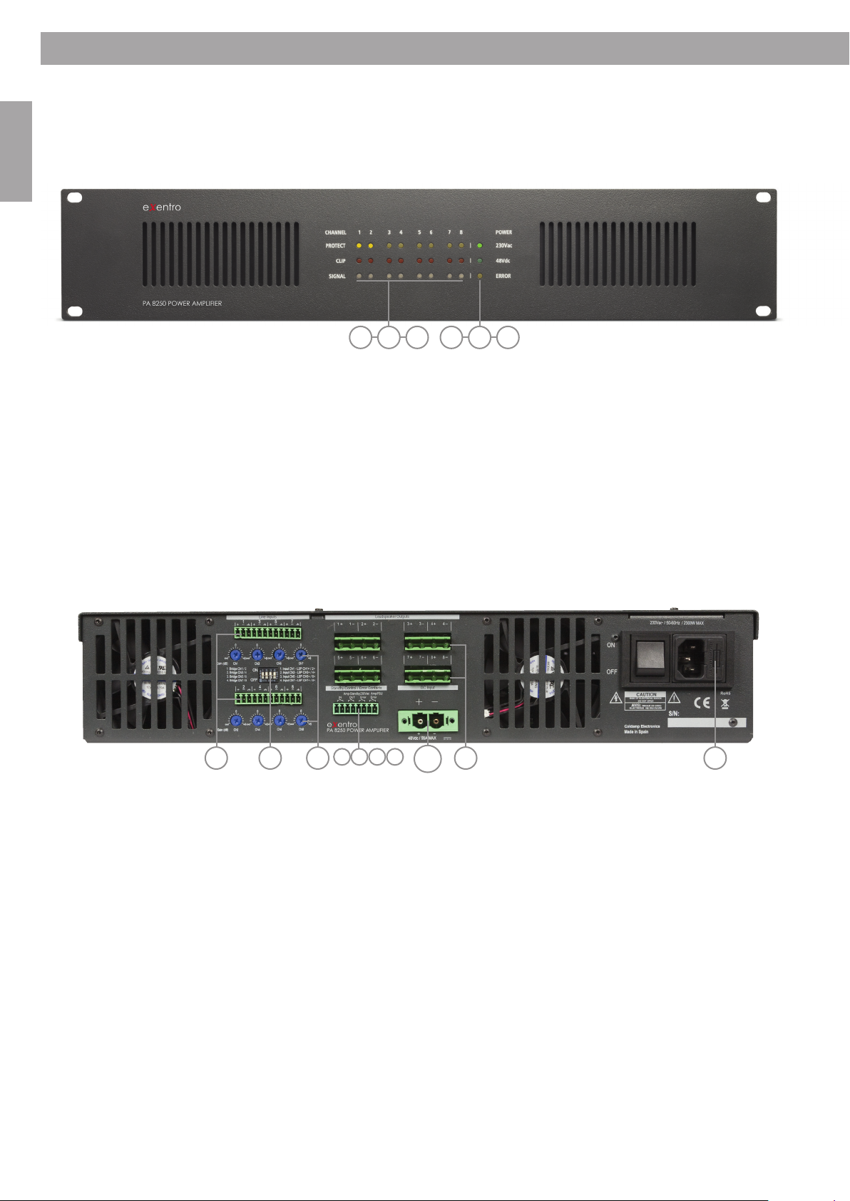
7.1 Front panel indicators
English
4 5 61 2 3
Channel 1 to 8:
1. PROTECT – YELLOW – indicates a fault or activated protection circuit
2. CLIP – ORANGE – indicates a clipping audio signal
3. SIGNAL – BLUE – indicates the presence of input signal
Power Supply:
4. 230 Vac – GREEN – indicates the presence of the 230 Vac mains voltage
5. 48 Vdc – GREEN – indicates the presence of the 48 Vdc battery voltage
6. ERROR – YELLOW – indicates a fault in 1 of the 2 power supplies
7.2 Rear panel connection and controls
1 2 43 10
1. Analog balanced line level inputs (Ch.1 – 8)
2. Input gain controls (Ch. 1 – 8)
3. Dipswitch for Bridge mode settings (Ch.1 – 8)
4. 50 Vrms/Low Impedance Loudspeaker outputs (Ch. 1 – 8)
5 6 7 8
9
5. Standby mode input – when trigered (contact closure) the internal SMPS will switch into
standby mode
6. Standby mode link - output contact (NO) to link to standby input of next amplifier
7. 230 Vac error contact (NO) – when closed it indicates the loss of the 230 Vac input
8. Fault relay contact (NO) – indicates a general amplifier failure and/or power supply failure
9. 230 Vac input & power switch (OFF position will not affect the 48 Vdc input)
10. 48 Vdc battery input for emergency battery backup
8
8. Configuration
8. Configuration
8.1 Balanced and unbalanced Inputs
The amplifier can accept unbalanced and balanced lines. For optimal performance and with
longer cable runs, use balanced lines whenever possible. The driving device should be equipped
with a balanced output. With short cables inside one rack the issue is not that critical.
A balanced connection provides excellent noise immunity from interference and ground loops.
A balanced audio connection is accomplished by using a differential pair of signals, isolated
from ground. While these connections provide great noise immunity, care must be taken when
connecting balanced and unbalanced equipment together.
8.2 Input Gain Controls
The amplifier is equipped with rear gain control for each channel. The gain range of the control
is from – infinite to +6 dB (0 dB in middle position). Full gain of the amplifier is reached with a
balanced input signal of 1.85 Vrms (with gain setting at 0 dB). In bridge mode only 1 input gain
(nr. 1, 3, 5 and/or 7) is operating.
8.3 Audio Limiters
English
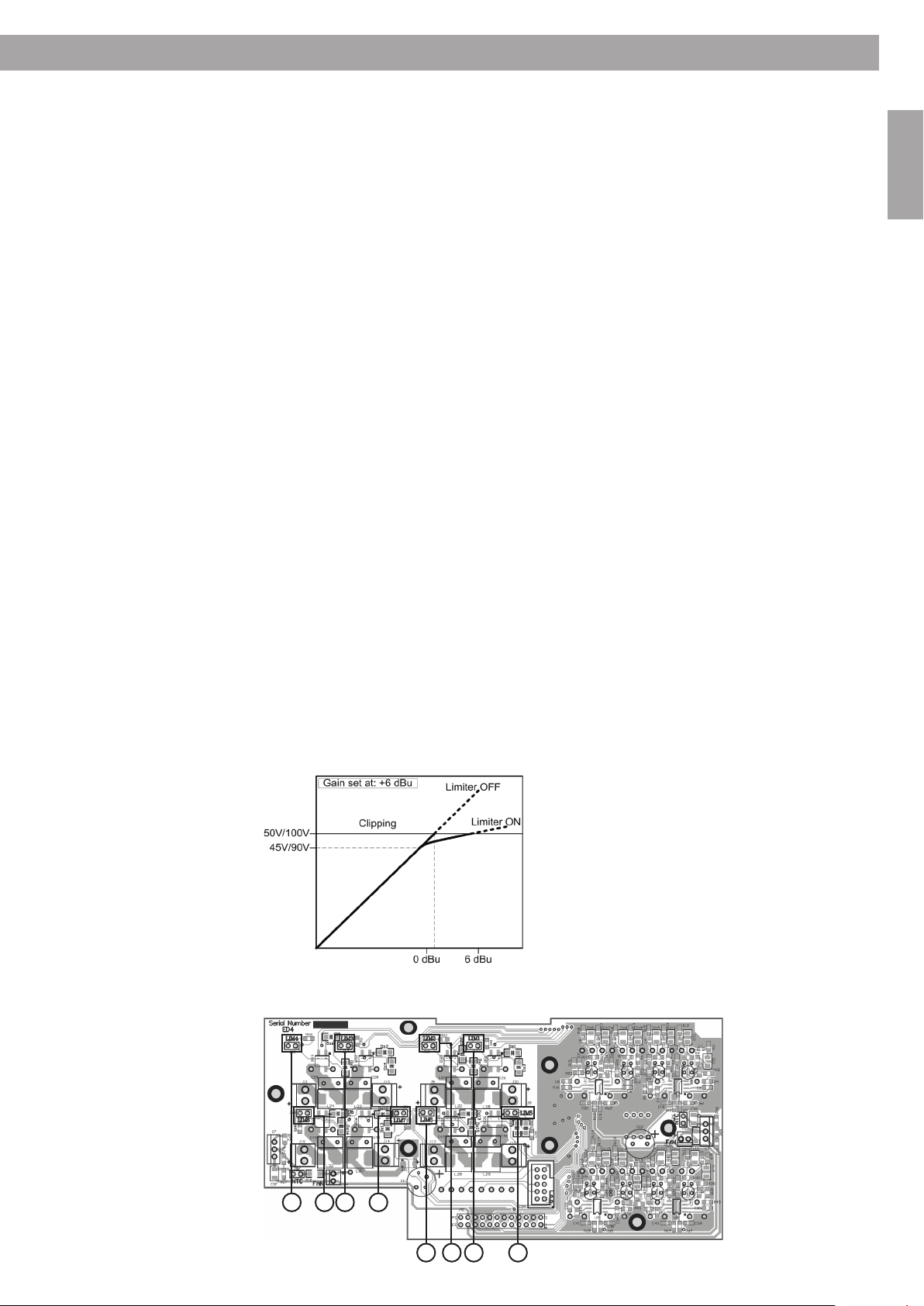
To reduce severe clipping, which can result in overloading of an amplifier channel, each channel
is equipped with a soft-limiter. The limiter circuit senses the output signal and when it starts
to reach its maximum output level the input signal is reduced accordingly. If one continues to
run the amp with high input signal beyond the limiters capabilities, the amplifier channel(s)
will start clipping again, distortion will increase rapidly and the overload protection circuit will
be trigered (channel(s) will turn off for a moment)! To avoid this: reduce the input signal until
clipping indicators do not light up anymore. The limiters are factory activated and can be turned
off by removing an internal jumper (1 per channel), see picture below. When a channel pair is
running in bridge mode, for example Ch.1 & Ch.2, only the limiter for Ch.1 is operating (Lim.3 for
Ch3/4, Lim.5 for Ch5/6 and Lim.7 for Ch7/8).
NOTE: To change the limiter setting, make sure the amplifier is disconnected from any AC-mains
and DC-battery connection before opening the unit!
4 8 3 7
Jumpers on rear
vertical board
(remove to
de-activate):
1. Limiter channel 1
2. Limiter channel 2
3. Limiter channel 3
4. Limiter channel 4
5. Limiter channel 5
6. Limiter channel 6
7. Limiter channel 7
8. Limiter channel 8
6 2 1 5
9
8. Configuration
8.4 Grounding
English
8.5 Loudspeaker equalization
The chassis of the amplifier is connected with the ground of the AC power cord. As soon as
several devices are connected with each other in a signal chain, a ground loop is created. Ground
loops are caused when current flows from the analog ground plane of one device to the ground
plane of another device. A compensating current travels between the different devices on the
shields of the audio cables. This may cause hum problems.
For use with active equalized Bose loudspeakers please use a Bose loudspeakers controller or the
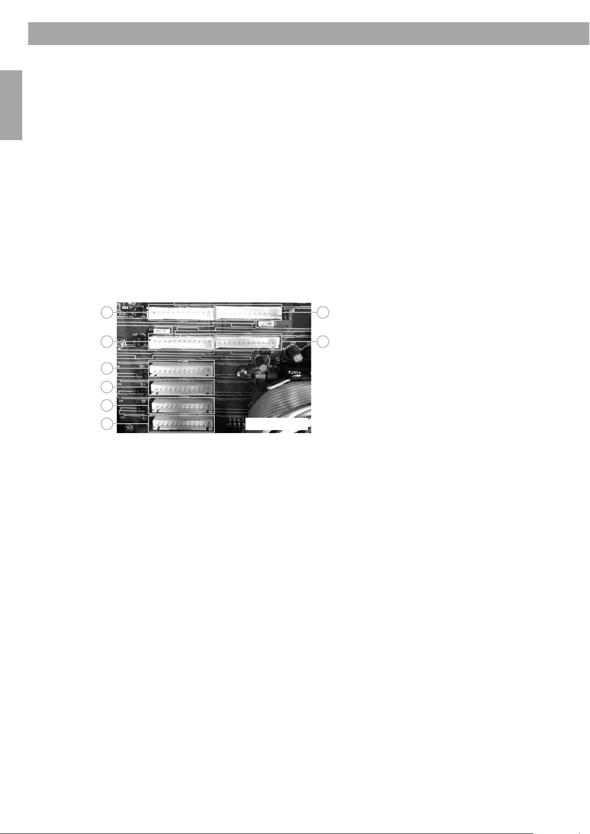
appropriate EQ Cards (Bose EQ Card Series II-s). To install the EQ cards, make sure the amplifier is
disconnected from any AC-mains and DC- battery connection before opening the unit.
Remove the jumper next to the EQ socket before the EQ card is installed (see picture below).
If the appropriate jumper is not removed an oscillating signal may occur. In bridge mode only
1 EQ card is needed (placed on position 1A for Ch1, 2A for Ch2, 3A for Ch3 and 4A for Ch4).
7 8
5 6
4
3
2
1
8.6 Loudspeaker Output Connections
Use heavy gauge wire for speaker connections. The larger the distance is between the amplifier
and speakers, the larger the diameter of the wire should be. This will minimize power losses
across the wire and improve damping of the speaker. See chapter 10 ‘Technical Specifications’ for
the minimum connected loudspeaker impedance and Appendix A for more info on wire thickness
and cable losses.
CAUTION: All amplifier outputs which run in bridge mode can have an output voltage swing of
100 Vrms (50 Vrms max when not bridged). Turn the amplifiers completely off before connecting
any loudspeaker wiring to the output terminals to avoid an electric shock.
REAR OF UNIT
EQ card and Jumper position:
1. Position 1A = channel 1; remove jumper J32
2. Position 1B = channel 2; remove jumper J34
3. Position 2A = channel 3; remove jumper J33
4. Position 2B = channel 4; remove jumper J35
5. Position 3A = channel 5; remove jumper J36
6. Position 3B = channel 6; remove jumper J37
7. Position 4A = channel 7; remove jumper J38
8. Position 4B = channel 8; remove jumper J39
8.7 Output power allocation
10
In normal operation each output channel can deliver the same output power (in equal connected
loads), all channels driven. See examples below and chapter: Technical Specifications.
A single amplifier channel has a maximum power capability of 250 Wrms a 50 V (10 ohm),
300 Wrms at 8 ohm and 200 Wrms at 4 ohm, and in bridged mode: 500 Wrms at 100 V (20 ohm),
600 Wrms at 16 ohm and 400 Wrms at 8 ohm.
Bridge Mode: to run 2 channels in bridge mode, for example channel 1 & 2; set dipswitch 1 to 'ON'
position, connect the loudspeaker to outputs 1+ (hot) and 2+ (cold) and apply the input signal to
input Ch1 only. See also text labels next to 'dipswitch' at the rear of the amplifier.
The total output power available of the PA 8125 can be allocated between all 8 channels is 1000 W.
The total output power available of the PA 8250 is 2000 W, of which 1000 W can be allocated
between channel 1, 2, 7 & 8 and another 1000 W to be allocated for channel 3, 4, 5 & 6. Below
tables show examples of allocating output power between different channels.
 Loading...