

Grafik Eye 4100, 4500 Installer's Manual
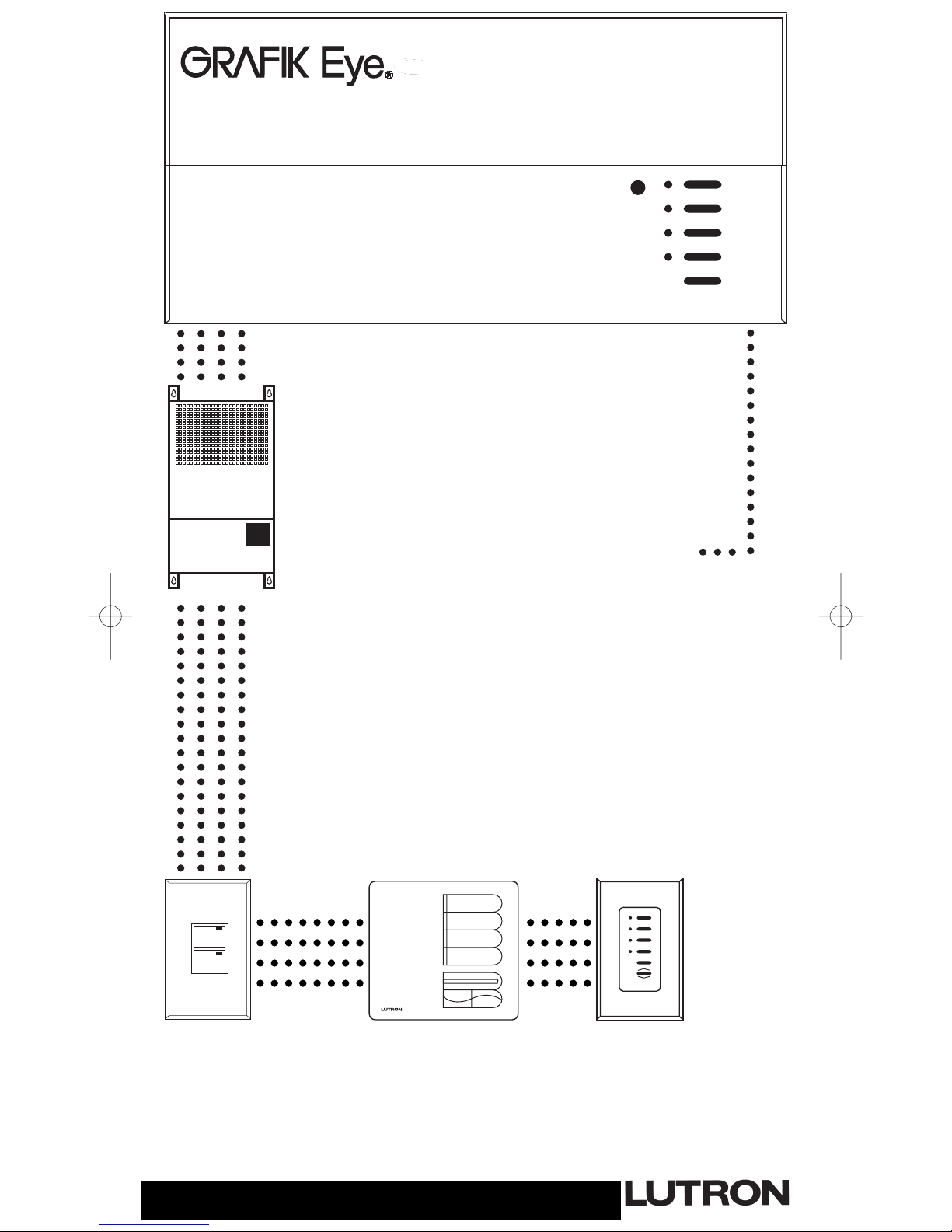
GRAFIK Eye 4000 Series
Control Units, in conjunction with
a Lighting Control Panel, control
the brightness of two, three, four,
six, eight, sixteen, or twenty-four
zones of lighting. GRAFIK Eye
Control Units control the intensity
of all the light sources in a
room. You can adjust the lights for
a special event or activity with
the press of a button!
LIGHTING CONTROL
LUTRON
LUTRON
PLEASE LEAVE FOR OCCUPANT
4000 Series
Installer’s Guide
Models 4100 and 4500
GRAFIK Eye Control Unit
FADE TEMPORARY
MASTER
ZONES
ZONE 1 ZONE 2
M S
To Set Up GRAFIK Eye:
1.Select a Scene.
2.Adjust light level
of each Zone.
3.Repeat for each Scene.
To Operate GRAFIK Eye:
Press a Scene button to recall
its corresponding light levels.
Press the Off button to turn all
lights off.
For more setup options, refer
to the literature supplied with
your GRAFIK Eye, or call
Lutron Electronics Co., Inc.
P/N 500-8723
U.S.A., Canada, Caribbean
Toll Free: (800) 523-9466
International: 1-610-282-3800
Europe
Freephone: 0800 282107 (U.K.)
International:44-171-702-0657
Hong Kong
Tel: 2104-7733
International: 852-2104-7733
Singapore
Tel: 65 487 2820
Lutron Worldwide Locations
ZONE 1
Internet: www.lutron.com
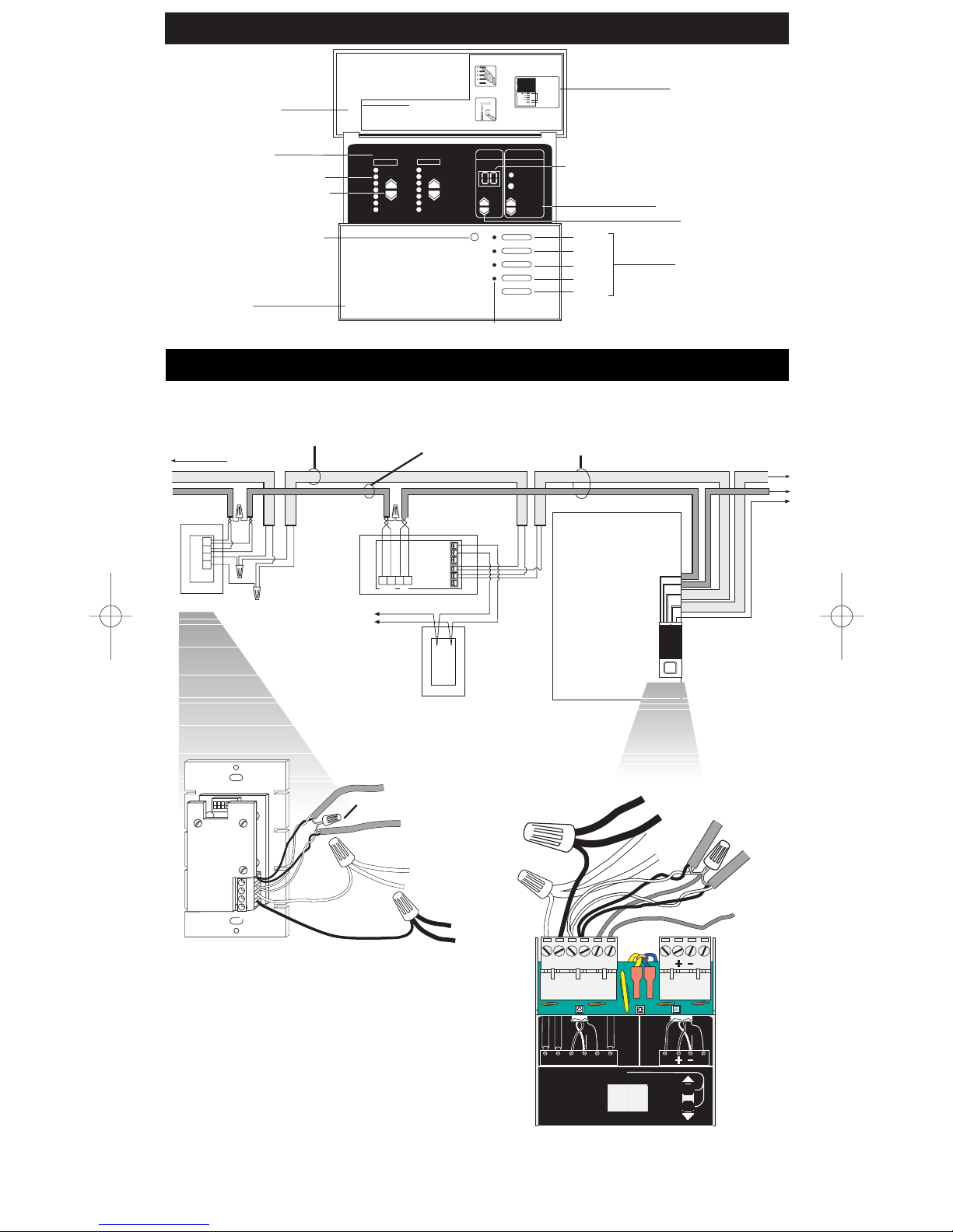
Scene button
Off button
HINGED COVER
ZONE LABEL
LIGHT LEVEL LED BARGRAPH
ZONE RAISE/LOWER BUTTONS
INFRARED WIRELESS
REMOTE CONTROL RECEIVER
BASE
INSTRUCTION LABEL
FADE WINDOW (IF ‘S’ IS LIT, TIME IS IN SECONDS,
IF ‘M’ IS LIT, TIME IS IN MINUTES)
MASTER RAISE/LOWER
FADE BUTTONS
SCENE BUTTONS
SCENE 1
SCENE2
SCENE 3
SCENE 4
OFF
SCENE INDICATOR LEDs
3
434
OUT
IN
SSA
SSARET
4
3
2
1
2
1
Page 2
4
3
2
1
SELECT CIRCUIT
2
1
Circuit
Data A OK
Power
1234 5D
Common
24VFW
MUX
MUX
Drain
Sense
1234
D
5
Data B OK
B
Comm
Drain
MUX
MUX
C
D
Link
C
D
A
Link
GRAFIK Eye Control Wiring Overview
To additional Control Units,
Wallstations, Panels, or Control
Interfaces
2 #12 AWG (2.5 mm
2
) from
Terminals 1 to 1, and 2 to 2
2 #18 AWG (1.0 mm2) twisted, shielded pair
from Terminals 3 to 3, and 4 to 4 (Belden #9461
or Alpha #2211 are recommended)
Lutron offers a one-cable (non-plenum), low-voltage, color-coded
solution for proper daisy-chaining of Control Units, Wallstations, and
Circuit Selectors (Lutron P/N GRX-CBL-46L) or all four wires are
available from Liberty Cable (P/N Lucom 12/22-RBL) at 1-800-530-
8998.
GP Panel
SSA Control
(NTGRX-1S)
GRX-4000 Series Control Unit
Wallstation
To additional Single-
Scene Activators
Drain—Keep short and isolated
2 #12 AWG (2.5 mm2)
2 #12 AWG (2.5 mm2)
1 #18 AWG (1.0 mm
2
)
1 #18 AWG (1.0 mm
2
)
Wallstation
2 #12 AWG (2.5 mm
2
)
1 #18 AWG
(1.0 mm
2
)
1 #18 AWG
(1.0 mm2)
5 to 5 (sense for
panel to panel)
Circuit Selector in the GP Panel
■ Connections are made inside the Wallstation’s backbox or in a
junction box located no more than 8 ft. (2.4 m) from the
Wallstation.
■ Total Control Wiring length is not to exceed 2000 ft. (450 m for
2.5 mm
2
) and must not be run in the same raceway as
line/mains voltage wiring.
■ Use the wire connector required by local code (those shown are
common in the U.S.).
■ Some of the products shown have removable terminal blocks.
■ Connect the Drain/Shield to Terminal “D”, if this terminal is
available. The Drain is a bare wire; care must be taken so that it
does not touch earth/ground or wallstation circuitry.
Page 3
Class 2/PELV Wiring
Class 2/PELV wiring is used to carry communications between GRAFIK Eye Control Units,
Wallstations, Control Interfaces, and the Circuit Selector.
Lutron requires that you connect (daisy-chain) all GRAFIK Eye Control Units and Wallstations
for proper operation. The drain wires must be connected to each other or to Terminal D, if
present. Drain wires should not be connected to Earth/Ground.
■ The 2 #12 AWG (2.5 mm
2
) wires are used to supply low-voltage power to the Control Unit
and Wallstations. These wires are connected to terminals 1 (COMMON) and 2 (24VFW).
■ The twisted pair is for a data link (up to 2000 ft. or 450 m long) that enables Wallstations to
communicate with GRAFIK Eye Control Units. Connect this twisted pair to Terminals 3
(MUX) and 4 (MUX) of every Control Unit and Wallstation.
Wallstation circuits are classified as Class 2 circuits (U.S.A) and PELV circuits (IEC). Unless otherwise specified,
the voltages do not exceed 24VAC or 15VDC. As Class 2 circuits, they comply with the requirements of NFPA
70, National Electrical Code (NEC). As PELV circuits, they comply with the requirements of IEC 60364-4-41,
VDE 0100 Part 410, BS7671:1992 and other equivalent standards. When installing and wiring to these
Wallstations, follow all applicable national and/or local wiring regulations. External circuits connected to input,
output, RS232, DMX512, and other communication terminals of Wallstations, must be supplied from a Listed
Class 2 source or comply with the requirements for PELV circuits as applicable in your country.
The GRAFIK Eye 4000 Series Control Unit Class 2/PELV circuit is 24VDC.
What is PELV?
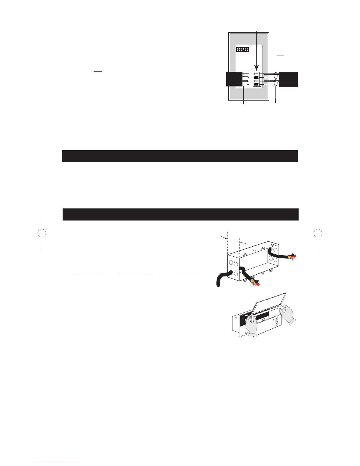
123456
4
3
2
1
EACH TERMINAL CAN ACCEPT UP TO
2 #18 AWG (1.0 mm2) WIRES
CLASS 2/PELV
POWER WIRING:
2: 24VFW
1: COMMON
2 #12 AWG (2.5 mm
2
)
1 #18 AWG (1.0 mm
2
)
twisted, shielded pair,
OR
Lutron P/N GRX-CBL46L
DATA LINK:
4: MUX
3: MUX
In countries that abide by the IEC regulations, PELV is commonly referred to as Protective Extra-Low Voltage. A PELV circuit is an earthed
circuit in which the voltage cannot exceed 50VAC or 120V ripple-free DC. The power source must be supplied by a safety isolating
transformer or equivalent.
IMPORTANT WIRING NOTES!
■ Use properly certified cable for all Class 2/PELV cables.
■ Install in accordance with all local and national electrical codes.
■ CAUTION! Do not connect line voltage/mains cable to Class 2/PELV terminals.
■ It is recommended that the Control Unit be earth grounded.
Preparation
1. Mount Wallbox. Use standard U.S. wallbox, 3 1/2 in. (87 mm) deep is
recommended, 2 3/4 in. (68 mm) deep minimum.
2. Pull Wires. Use the rearmost knockouts when pulling wires into the wallbox. This
will provide the most clearance when mounting the Control Unit.
3. Remove Cover.Remove the Control Unit’s cover and hinged faceplate by pulling
outward at each corner.
Model Number
Number of Zones Wallbox Size
4102/4502 2 2-Gang U.S
4103/4503 3 3-Gang U.S
4104/4504 4 4-Gang U.S*
4106/4506 6 4-Gang U.S*
4108/4508 8 4-Gang U.S*
4116/4516 16 4-Gang U.S*
4124/4524 24 4-Gang U.S*
* Lutron P/N 241-400.
Installation instructions.
3.5 in. (87 mm) deep recommended
230V
˜
LUTRON
50/60Hz
LOAD PER ZONE: 40 - 800W
MAX UNIT LOAD: 10A, 2300W
Preset Lighting Control
LIVE TERMINALS AT REAR
DO NOT WIRE LIVE
U. K. 071-702-0657
U. S. A. (610) 282-3800
COOPERSBURG, PA USA 18036
GRX-3104-CE
UP
Made in U.S.A.
12V
SELV OUTPUT
!
CB E 5
145-049
GRX-Z
 Loading...