

Grafik Eye 3100, 3500 Installer's Manual
○○○○○○○○○○○○○○○○○○○○○○○○○○○○○○○○○○○○○○
○○○○○○○○○○○○○○○○○○○○○○○○○○○○○○○○○○○○○○
○○○○○○○○○○○○○○○○○○○○○○○○○○○○○○○○○○○○○○
○○○○○○○○○○○○○○○○○○○○○○○○○○○○○○○○○○○○○○
○○○○○○○○○○○○○○○○○
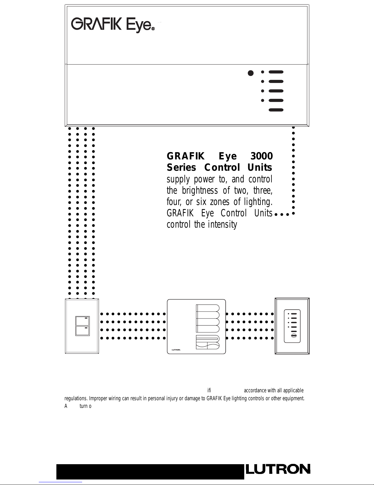
GRAFIK Eye 3000
Series Control Units
supply power to, and control
the brightness of two, three,
four, or six zones of lighting.
GRAFIK Eye Control Units
control the intensity of all the
light sources in a room. You
can adjust the lights for a
special event or activity with
the press of a button!
○○○
LIGHTING CONTROL
○○○○○○○○○○○○○○○○○○○○○○○○○○○○○○○○○○○○○○
○○○○○○○○○○○○○○○○○○○○○○○○○○○○○○○○○○○○○○
○○○○○○○○○○○○○○○○○○○○○○○○○○○○○○○○○○○○○○
○○○○○○○○○○○○○○○○○○○○○○○○○○○○○○○○○○○○○○
LUTRON
LUTRON
PLEASE LEAVE FOR OCCUPANT
3000 Series
Installer’s Guide
Models 3100 and 3500
IMPORTANT! GRAFIK Eye lighting controls must be installed by a qualified electrician in accordance with all applicable
regulations. Improper wiring can result in personal injury or damage to GRAFIK Eye lighting controls or other equipment.
Always turn off circuit breaker/MCB or remove main fuse from power line before doing any work. To avoid overheating and
possible damage to equipment, do not install dimming devices to dim receptacles, motor-operated appliances, or
fluorescent lighting not equipped with Lutron Hi-lume®, Eco-10™, or Tu-Wire™ Electronic Dimming Ballasts. In dimmed
magnetic low-voltage circuits, you can prevent transformer overheating and failure by avoiding excessively high current
flow: Do not operate GRAFIK Eye lighting controls with any lamps removed or burned out; Replace any burned out lamps
immediately; Use only transformers that incorporate thermal protection or fused primary windings. This lighting control is
designed for residential and commercial use. GRAFIK Eye Controls are designed for indoor use only.

Do you have: Then read this . . . . . . on page:
Control Unit only? STEP 1: Installing 3000 Series Control Units 3
Follow Step 1 and Step 3 How to wire and mount GRAFIK Eye 3000 Series Control Units.
Wallstations too? STEP 2: Installing Wallstations 4
DIP switch address settings, wiring, and mounting.
STEP 3: Setting Up Control Units 6
Identifying load types and setting up lighting scenes.
STEP 4: Setting Up System Communications 10
Assigning Wallstations to the Control Units they should operate.
Questions about Appendix A: More about Class 2/PELV Wiring 12
Class 2/PELV wiring?
Appendix B: Special Mounting Considerations 14
Appendix C: Power Boosters, 14
Electronic Low Voltage Interfaces,
and Fluorescent Dimming Ballast Interfaces
Appendix D: GRX-TVI 0-10 Volt Ballast Interface 15
Appendix E: HP 2•4•6 Dimming Modules 17
Appendix F: Infrared Controls 18
Problems? Appendix G: Troubleshooting 18
LUTRON-Quality Systems
Registered to ISO 9001
Page 2
Questions? Need technical assistance?
Phone Assistance . . . Worldwide!
■ In the U.S., Canada and the Caribbean:
1-800-523-9466
■ In Mexico, Central and South America:
1-610-282-3800
■ In Japan: 03-5405-7333
■ In Hong Kong: 2104-7733
■ In the U.K.: 0800-282-107
■ In Europe: 44-171-702-0657
■ All others: 1-610-282-3800
■ Website address: www.lutron.com
■ E-mail: product@lutron.com
Warranty
Lutron warrants each new unit to be free from defects in materials and workmanship and to perform under normal use and service. This
warranty shall run only for a period of one year from the date of purchase and Lutron's obligations under this warranty are limited to
remedying any defect or replacing any defective part and shall be effective only if the defective unit is shipped to Lutron postage prepaid within
12 months after purchase. Damage due to abuse, misuse, inadequate wiring or installation is not covered by this warranty. In no event shall
Lutron or any other seller be liable for any other loss or damage, including consequential or special damages that may arise through the use
by a purchaser or others of this device and the purchaser assumes and will hold harmless Lutron in respect of all such loss. Although every
attempt is made to ensure that catalogue information is accurate and up-to-date, please check with Lutron before specifying or purchasing this
equipment to confirm availability, exact specifications and suitability for your application. This product may be covered by one or more of the
following U.S. patents: 4,797,599; 4,803,380; 4,825,075; 4,893,062; 5,030,893; 5,191,265; 5,430,356; 5,463,286; 5,530,322; 5,808,417;
DES 308,647; DES 310,349; DES 311,170; DES 311,371; DES 311,382; DES 311,485; DES 311,678; DES 313,738; DES 335,867; DES
344,264; DES 370,663; DES 378,814 and corresponding foreign patents. U.S. and foreign patents pending. Lutron, GRAFIK Eye, and Hi-lume
are registered trademarks; Hi-Power, Eco-10, LIAISON, Designer, Tu-Wire, and Architrave are trademarks of Lutron Electronics Co., Inc. ©
1999 Lutron Electronics Co., Inc.
®
Safety standards listed above apply to one or more products in the GRAFIK Eye product line. Consult factory for specific information.
2
3
0
V
˜
LUTRON
5
0
/6
0
H
z
L
O
A
D
P
E
R
Z
O
N
E
: 4
0
- 8
0
0
W
M
A
X
U
N
IT
L
O
A
D
: 1
0
A
, 2
3
0
0
W
P
re
s
e
t L
ig
h
tin
g
C
o
n
tro
l
LIVE
TER
M
IN
A
LS A
T R
EA
R
D
O
N
O
T W
IR
E
LIV
E
U
. K
. 0
7
1
-7
0
2
-0
6
5
7
U
. S
. A
. (6
1
0
) 2
8
2
-3
8
0
0
C
O
O
P
E
R
S
B
U
R
G
, P
A
U
S
A
1
8
0
3
6
GRX-3104-CE
U
P
M
a
d
e
in
U
.S
.A
.
1
2
V
S
E
L
V
O
U
T
P
U
T
!
C
B
E
5
1
4
5
-0
4
9
G
R
X
-Z
Page 3
HOT/LIVE
SWITCH
LOAD
NEUTRAL
STEP 1: Installing Control Units
This section shows how to install Control Units and make sure they are properly operating all connected loads.
CAUTION!
First test loads for short circuits.
1. Turn power OFF at the breaker/MCB panel or fuse box.
2. Connect standard light switch between live lead and the load wire to test circuit.
3. Turn power on and check for short or open circuits: If load does not operate, circuit is open. If the
breaker/MCB trips (fuse blows or opens), circuit is shorted. Correct short or open circuits and test
again.
Load Types
The Control Units can control incandescent, halogen (tungsten), magnetic low-voltage, and neon/cold cathode load types. Electronic lowvoltage and fluorescent load types can be controlled with an appropriate interface.
■ Not all zones need to be connected; however, connected zones must have a load of at least 25W (40W for AU and CE models).
■ No zone may be loaded with more than 800 W (1200 for AU models).
■ Unit must not carry more than 16A of total lighting load (10A for CE models).
■ All Electronic Low-Voltage (ELV) lighting used with the Electronic Low-Voltage Interface must be rated for reverse phase-control
dimming. Before installing an ELV light source, verify with the manufacturer that their transformer can be dimmed. When dimming, an
Electronic Low-Voltage Interface MUST be used with the Series Control Unit.
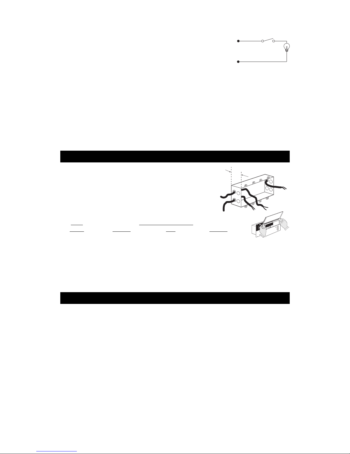
Installation instructions. First, turn power off.
Preparation
1. Mount Wallbox. Use standard U.S. wallbox, 3 1/2 in. (87 mm) deep is strongly
recommended, 2 3/4 in. (68 mm) deep minimum. Always allow at least 4 1/2 in. (110 mm)
clearance above and below the faceplate to ensure proper heat dissipation.
2. Pull Wires. Use the rearmost knockouts when pulling wires into the wallbox. This will
provide the most clearance when mounting the Control Unit.
3. Remove Cover. Remove the Control Unit’s cover and hinged faceplate by pulling outward at
each corner.
Model Wallbox Size/Max. Unit Load
Number 100-127V 230V 220-240V
3102/3502 2-Gang U.S
†
/1200W/VA 4-Gang U.S†/10A 2-Gang U.S/1600W/VA
3103/3503 3-Gang U.S
†
/1500W/VA 4-Gang U.S†/10A 3-Gang U.S/2400W/VA
3104/3504 4-Gang U.S
†
/2000W/VA 4-Gang U.S†/10A 4-Gang U.S†/3000W/VA
3106/3506 4-Gang U.S†/2000W/VA 4-Gang U.S†/10A 4-Gang U.S†/300W/VA
† Lutron P/N 241-400.
Line Voltage/Mains Wiring
IMPORTANT WIRING NOTES!
■ Use properly certified cable for all line voltage/mains cables and
Class 2/PELV cables.
■ In Europe, acceptable types of cable include HAR certified cable
with insulated cores enclosed in a sheath. This cable must bear the
appropriate certification mark pertaining to national wiring rules for
fixed installations. If certified cable with insulated cores enclosed in
a sheath is used for the Power cables, the Class 2/PELV wiring can
be any of the specified cables in Appendix A: More about
Class 2/PELV Wiring.
■ Proper short-circuit and overload protection must be provided at
the distribution panel. You can use up to a 20A (16A for AU, and
10A for CE models) maximum circuit breaker/MCB or equivalent
(tripping curve C according to IEC60898/EN60898 is
recommended) with adequate short-circuit breaking capacity for
your installation.
■ Install in accordance with all local and national electrical codes.
■ CAUTION! Do not connect line voltage/mains cable to Class 2/
PELV terminals.
■ Earth/Ground terminal connection must be made as shown in
wiring diagrams.
■ Do not mix different load types on the same zone!
■ Fluorescent and electronic low voltage loads require
interfaces. Zone loads that exceed 800W/VA (1200W/VA for
AU models) and total unit loads that exceed the unit capacity
require power boosters. Refer to Appendices C, D, E, and F.
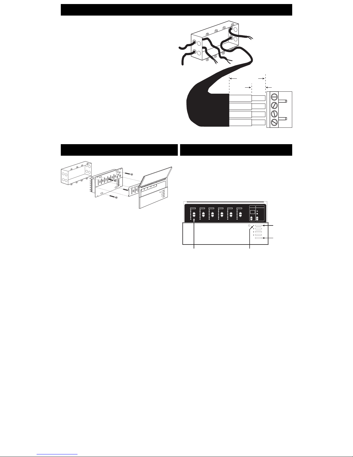
Wire the Control Unit (see Page 16)
1. Strip 1/2 in. (12 mm) insulation from all wires in wallbox and
connect them to appropriate terminals on the back of the
Control Units. The recommended installation torque is 9.0
in.
●
lbs. (1.0 N●m) for line voltage connections and 10 in.●lbs.
(1.3 N
●
m) for the earth/ground connection. Each power
terminal can accept up to two #12 AWG (2.5 mm
2
) wires. (Does
not apply to Class 2/PELV terminal block.)
3.5 in. (87 mm) DEEP RECOMMENDED
Class 2/PELV Wiring
M S
FADE TEMPORARY
MASTER
ZONES
ZONE 5 ZONE 6ZONE 3 ZONE 4ZONE 1 ZONE 2
Scene 1
button
OFF
Zone intensity raise and lower
buttons
Scene 1 LED
Page 4
1
2
3
4
LINE VOLTAGE/MAINS CABLE
CLASS 2/PELV
TERMINAL
CLASS 2/PELV CABLE
1.0 in. (25 mm)
3/8 in.
(9.5 mm)
LINE VOLTAGE/MAINS CABLE
1. Mount as shown using the four screws provided. (When mounted in
the wallbox, the Class 2/PELV cable and terminal block should
remain separated from the line voltage/mains cables.)
2. Reattach the faceplate to the Control Unit by pushing inward at each
corner.
Testing: Do the lights work?
IMPORTANT WIRING NOTES!
Review Appendix A BEFORE wiring!
■ Wallstations must be installed by a qualified electrician.
■ Wallstations use Class 2 or PELV wiring methods as applicable in your
locale.
— Using Class 2 wiring methods: Wallstations must be connected in
accordance with the 1996 National Electrical Code, Article 725-54(a),
(1) Exception No. 3 or the Canadian 1994 CE Code Handbook, Rule
16-212, Subrule (4). Check with your local electrical inspector to
comply with local codes and wiring practices.
— Using PELV wiring methods: Wallstations that are connected to
terminals 1—4 must always meet the requirements of DIN VDE 0100
Part 410 and IEC 60364-4-41 for PELV circuits. See “What is PELV?”
in Appendix A.
■ Wallstations must be mounted in a wallbox. Please refer to instruction sheet
included with each Wallstation to determine wallbox requirements.
■ Note that the NTGRX-1S can use line voltage/mains branch circuit wiring.
Refer to the installation instructions packaged with the Wallstation.
Connect Class 2/PELV wiring
only if your project has Wallstations
and/or more than one Control Unit
.
Use recommended cable as specified in Appendix A: More About
Class 2/PELV Wiring.
Wiring Note
■ Use the rearmost knockouts when pulling wires into the wallbox.
This will provide the most clearance when mounting the Control
Unit.
1. Strip 1 in. (25 mm) of insulation from the Class 2/PELV cable.
2. Strip 3/8 in. (8 mm) of insulation from each wire.
3. Connect the Class2/PELV wires to the Class 2/PELV
terminal block. Make sure no bare wire is exposed after
making connections. The recommended installation torque is
3.5 in.
●
lbs. (0.4 N●m) for Class 2/PELV connections.
4. The Class 2/PELV cable and terminal block should be separated
from line voltage/mains cables by at least 1/4 in. (7 mm).
Mounting
1. Restore Power.
2. Press Scene 1 button on front of the GRAFIK Eye Control
Unit. The Scene 1 LED will light.
3. Press zone
55
55
5 or
66
66
6 to raise or lower the light levels. Make
sure that the Control Unit is dimming all connected loads. Refer
to Appendix G: Troubleshooting, or call Lutron.
STEP 2: Installing Wallstations
Examples of Wallstations
NTGRX-2B-SL Entrance/Special Function Control
NTGRX-4S Scene Selection Control with Raise/
Lower
NTGRX-4S-IR Scene Selection Control/Infrared
Receiver
NTGRX-4B Scene Selection Control
NTGRX-4M Master Control
NTGRX-4PS Partition Control
GRX-CIR* Infrared Ceiling Receiver
GRX-4S-DW* ArchitraveTM Door Jamb Control
GRX-AV* Interface Control
GRX-RS232* RS-232 Interface Control
GRX-PRG* Personal Computer Interface
GRX-IT/GRX-8IT Infrared Handheld Transmitter
(see Appendix C)
EGRX-4S* European Style 4S Control
EGRX-4S-IR* European Style 4S Control/Infrared
Receiver
. . . and more!
Page 5
56
56
56
56
56
56
1234
1
2
3
4
5
6
7
8
1234
9
10
11
12
13
14
15
16
*
FOR THIS ADDRESS . . .
SET SWITCHES
LIKE THIS:
RECORD LOCATION
AND TYPE OF
CONTROL HERE
SET SWITCHES
LIKE THIS:
RECORD LOCATION
AND TYPE OF
CONTROL HERE
123456
1234
DIP SWITCHES 1—4
SET ADDRESS
567
567
567
567
567
567
567
567
Class 2/PELV
Terminal
Class 2/PELV Cable
123456
1
4
3
2
4
3
2
1
CU WIRE ONLY
USA: Class 2
IEC: PELV
CONTROL UNIT
WALLSTATION
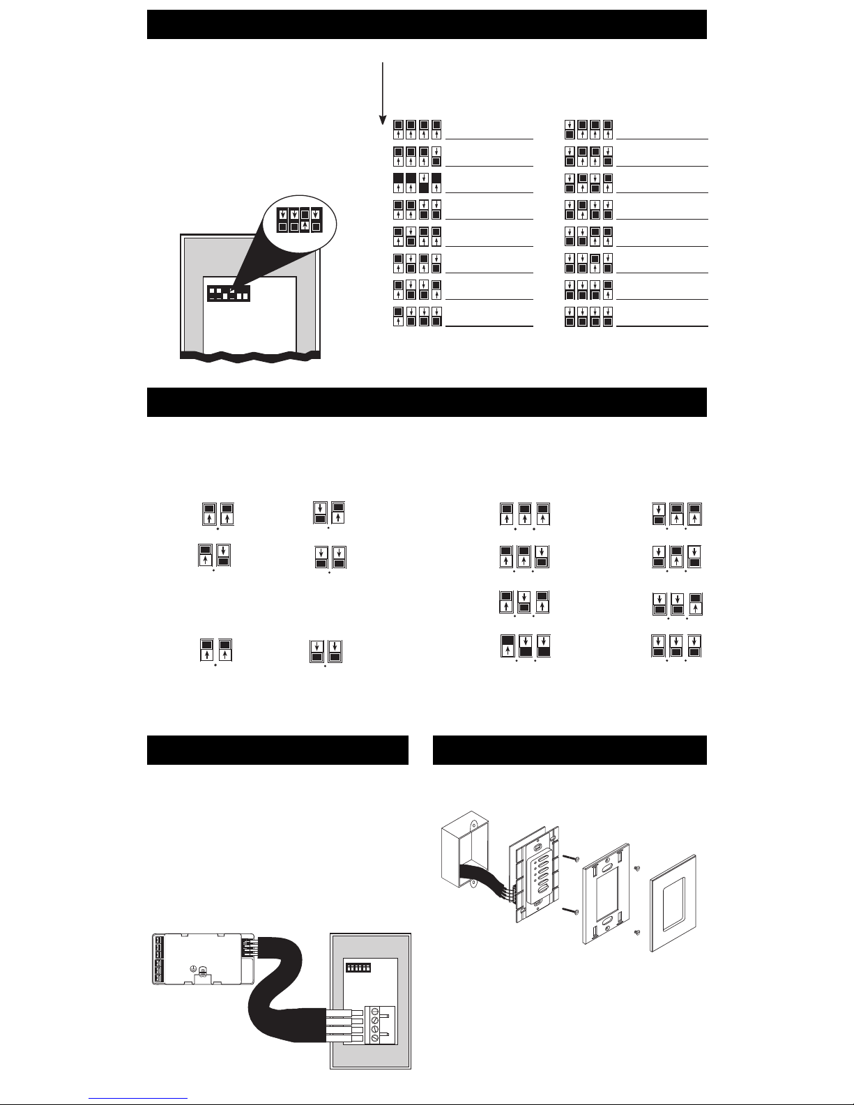
Set DIP switches 1—4 with unique system address
Each Wallstation must have a
unique
system address
(1—16) to identify the Wallstation and enable it to
communicate with the Control Unit(s).
To set its address, set DIP switches 1—4 to one of
the configurations shown at right (GRX-PRG
automatically assumes address 16). Document your
assignments by noting each Wallstation’s address.
* Reserved for GRX-PRG, if present on link.
Set DIP switches 5, 6 and/or 7 to specify function
For most Wallstations, you must also set DIP switches to specify exactly how the Wallstation is to function. Please refer to the Instructions
shipped with each Wallstation for more detailed information.
NTGRX-4S, -4S-DW, -4S-IR, -CIR, -4B
Scene Selection Control
Switches 5 and 6 determine which scenes the unit will select:
Scenes Scenes
1 to 4 9 to 12*
Scenes Scenes
5 to 8* 13 to 16*
NTGRX-4M
Master Control
Switches 5 and 6 determine whether bottom button turns lights on
or off:
ON OFF
only only
NTGRX-2B-SL
Multi-Control
Switches 5, 6 and 7 determine the function of the unit’s two buttons:
Scene 1 Fine Tuning
and Off Control
Scene 9/ Partition
Scene 10* Status
Scene 13/ Zone
Scene 14* Lockout
Panic Sequencing
Control Scenes 5—16*
* When using a Wallstation to access scenes 5—16, the scene LEDs will illuminate only on the Wallstation—not on the GRAFIK Eye
Control Unit.
Turn off power and wire
Review Appendix A: More About Class 2/PELV Wiring
before proceeding!
1. Mount 1-gang U.S. wallbox*, 2 3/4 in. deep (68 mm)
minimum.
2. Strip 3/8 in. (9 mm) insulation from both twisted pairs in the
wallbox.
3. Connect two #18 AWG (1.0 mm
2
) twisted pairs for Class 2/
PELV wiring (daisy-chain between stations)
†
.
4. Confirm all connections.
Mounting
Place twisted pairs in wallbox and mount as shown. Restore power.
* Some Wallstations have special mounting considerations. Please
refer to the detailed instructions supplied with each Wallstation.
† If shielded wire is used, the drain wire must also be daisy-
chained. Do not connect drain wire to earth/ground or
Wallstation (unless a “D” terminal is present).
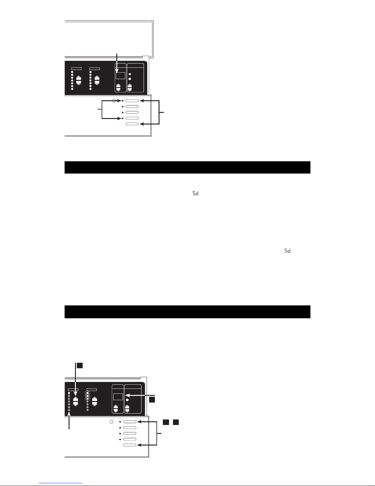
STEP 3: Setting Up GRAFIK Eye Control Units
Page 6
To enter setup mode: Press and hold the Scene 1 and OFF
button for about three seconds, until the scene LEDs start cycling.
To exit setup mode: Exit setup mode the same way you entered
it. Press and hold the Scene 1 and OFF button for about 3
seconds, until scene LEDs stop cycling. The Control Unit is out of
setup mode; back in normal operating mode.
In setup mode, the FADE window displays the setup codes. To
scroll through the menu of setup codes, press the FADE
5 or
5 buttons.
Identifying the load type for each zone
1. Enter setup mode. Press and hold Scene 1 and OFF buttons for
about 3 seconds, until scene LEDs cycle.
2. Check for LS in FADE window. (LS is the first code to appear
when you enter setup mode. For the LS mode, ZONE LEDs turn on
from top to bottom.)
3. Set each zone’s load type. Press ZONE
5 and 5 until
ZONE LEDs match the load type connected to each zone. Refer to
chart on next page.
4. Exit setup mode. Press and hold Scene 1 and OFF buttons for
about 3 seconds, until scene LEDs stop cycling.
In the 6-Zone Control Unit shown here:
■ Zone 5 is set for incandescent or magnetic low-voltage.
■ Zone 6 is set for neon/cold cathode.
This section shows how to set up a GRAFIK Eye Control Unit,
including:
■ Identifying the load type for each zone of lighting
connected to the Control Unit.
■ Setting up the scenes to create the desired lighting
effects, and make sure the Control Unit is working
correctly.
To set up the GRAFIK Eye Control Unit, enter the “setup
mode” and use the menu of setup codes that appear in the
FADE window. Step-by-step instructions for using the setup
codes are on the following pages.
How to enter and exit setup mode
The following is a list of the setup codes and their descriptions:
Code Stands for Description
Save Options Select from several save options (p.
9)
Sc Scene Set unaffected zones and set any of
the 16 scenes (p. 9)
A- Address Identify Control Units when setting
up system communications (p. 10)
LS* Load Select Identify load type (p. 7)
LE Low End Set low end trim (p. 8)
*When you enter setup mode, this code appears first.
■ If you press FADE 5, you will see A-, Sc, then .
■ If you press FADE 6, you will see LE.
Lutron ships GRAFIK Eye Control Units with all zones set for
incandescent/halogen (tungsten) lighting. If your project has nonincandescent loads, change all non-incandescent zones to the
correct load type.
FADE TEMPORARY
MASTER
ZONES
ZONE 5 ZONE 6
M S
LS
3
2
1 4
,
SET EACH ZONE’S LOAD TYPE
CHECK FOR LS
ENTER (EXIT)
SETUP MODE
ZONE LEDs
FADE TEMPORARY
MASTER
ZONES
ZONE 5 ZONE 6
M S
LS
TO ENTER (EXIT)
SETUP MODE:
PRESS AND HOLD FOR
ABOUT 3 SECONDS
UNTIL LEDs CYCLE
(STOP CYCLING)
LEDs
SCROLL THROUGH SETUP CODES
 Loading...