

Grafik Eye 3000 Series, 3100, 3500 Installer's Manual
®
3000 Series
In stall er’s Guide
Control Unit Mod els 3100 and 3500
LUTRON
PLEASE READ
Section 1: Introduction
GRAFIK Eye® 3000 Series Control Unit . . . . . . . . . . . . . . . . . . . . . . . . . . . . . . . . . . . . . . . . . . 2
System Communications and Capacities . . . . . . . . . . . . . . . . . . . . . . . . . . . . . . . . . . . . . . . . 3
Section 2: Installing a GRAFIK Eye® Control Unit
Step 1: Test the Loads for Short Circuits . . . . . . . . . . . . . . . . . . . . . . . . . . . . . . . . . . . . . . . . 4
Step 2: Turn the Power OFF . . . . . . . . . . . . . . . . . . . . . . . . . . . . . . . . . . . . . . . . . . . . . . . . . . 4
Step 3: Mount the Wallbox . . . . . . . . . . . . . . . . . . . . . . . . . . . . . . . . . . . . . . . . . . . . . . . . . . . 5
Step 4: Connect the Line Voltage/Mains Cables to the Control Unit . . . . . . . . . . . . . . . . . . . . 5
Step 5: Connect PELV (Class 2: USA) Cable to the Control Unit — Optional . . . . . . . . . . . . . 6
Step 6: Mount the Control Unit . . . . . . . . . . . . . . . . . . . . . . . . . . . . . . . . . . . . . . . . . . . . . . . . 7
Step 7: Test the Control Unit. . . . . . . . . . . . . . . . . . . . . . . . . . . . . . . . . . . . . . . . . . . . . . . . . . 7
Step 8: Connect the Wallstations — Optional . . . . . . . . . . . . . . . . . . . . . . . . . . . . . . . . . . . . . 8
Step 9: Connect Other Accessories — Optional . . . . . . . . . . . . . . . . . . . . . . . . . . . . . . . . . . . 8
Step 10: Connect Multiple Control Units — Optional. . . . . . . . . . . . . . . . . . . . . . . . . . . . . . . . 9
Special Mounting Considerations . . . . . . . . . . . . . . . . . . . . . . . . . . . . . . . . . . . . . . . . . . . . . . 9
Installing an External Power Supply . . . . . . . . . . . . . . . . . . . . . . . . . . . . . . . . . . . . . . . . . . . . . 10
Section 3: Programming a GRAFIK Eye® Control Unit
Control Unit Buttons and Indicators. . . . . . . . . . . . . . . . . . . . . . . . . . . . . . . . . . . . . . . . . . . . . 11
Entering and Exiting Setup Mode . . . . . . . . . . . . . . . . . . . . . . . . . . . . . . . . . . . . . . . . . . . . . . 11
Identifying the Load Type for Each Zone . . . . . . . . . . . . . . . . . . . . . . . . . . . . . . . . . . . . . . . . . 12
Programming Scenes . . . . . . . . . . . . . . . . . . . . . . . . . . . . . . . . . . . . . . . . . . . . . . . . . . . . . . . 14
Adjusting High or Low End Trim . . . . . . . . . . . . . . . . . . . . . . . . . . . . . . . . . . . . . . . . . . . . . . . 17
Selecting the Save Mode You Want to Use. . . . . . . . . . . . . . . . . . . . . . . . . . . . . . . . . . . . . . . 17
Section 4: Using the GRAFIK Eye® Control Unit
Selecting Scenes. . . . . . . . . . . . . . . . . . . . . . . . . . . . . . . . . . . . . . . . . . . . . . . . . . . . . . . . . . . 18
Temporarily Adjusting Light Levels and Shade Positions . . . . . . . . . . . . . . . . . . . . . . . . . . . . 18
Setting Up System Communications . . . . . . . . . . . . . . . . . . . . . . . . . . . . . . . . . . . . . . . . . . . . 20
Appendix A: Troubleshooting . . . . . . . . . . . . . . . . . . . . . . . . . . . . . . . . . . . . . . . . . . . . . . . . . 22
Warranty . . . . . . . . . . . . . . . . . . . . . . . . . . . . . . . . . . . . . . . . . . . . . . . . . . . . . . . . . . . . . . . . . 23
Contact Information . . . . . . . . . . . . . . . . . . . . . . . . . . . . . . . . . . . . . . . . . . . . . . . . . . . . . . . . 24
English
Español Français Português NederlandsDeutsch
Chinese
This installer’s guide explains how to install and program a GRAFIK Eye 3000 Series control unit. Use this guide
in conjunction with installation instructions supplied separately with other GRAFIK Eye 3000 Series products.
R
LUTRON-Quality Systems
Reg is tered to ISO 9001
Italiano
R
Section 1:
M S
FADE TEMPORARY
MASTER
ZONES
ZONE 5 ZONE 6ZONE 3 ZONE 4ZONE 1 ZONE 2
Introduction
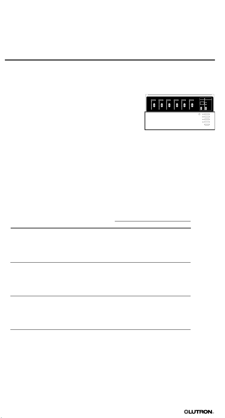
This section of the installer’s guide introduces the GRAFIK Eye 3000 Series lighting system
and control unit. This section also describes system communications and capacities. Read this
Introduction carefully before proceeding to the installation instructions beginning on page 4.
GRAFIK Eye® 3000 Series Control Unit
The GRAFIK Eye is part of a lighting control system that enables you to create customized
scenes and control lighting and shade zones.
The control unit is the centerpiece of the lighting control system. The control unit provides:
• Setup of lighting and shade control scenes using buttons on
the control unit.
• Pushbutton recall of four preset scenes, plus OFF.
• 12 additional scenes stored in the control unit, which are
accessible via optional wallstations and other control devices.
• Control of 2, 3, 4, or 6 zones.
• Smooth light level fading between scenes.
• Lockout options to prevent accidental changes.
• A built-in infrared receiver for operation with an optional remote control.
All of this can be accomplished on a single control unit. Up to 8 control units can be connected
together along with wallstations,
add additional control functions.
Additional features available with a 3500 model are accessed through PC control and include:
• Lighting level increments of 1%
• Virtual control through Liaison
• Shade control through RS232 interface
sensors, and other control interfaces to enlarge the system and
TM software
Model Numbers and Ratings
Model Number Voltage Ratings
50/60 Hz Unit Maximums Zone Ranges
2 Zones
GRX-3102, GRX-3502 120 V~ 1200 W/VA 25-800 W
GRX-3102-CE, GRX-3502-CE 230 V~ 1600 W/VA 40-800 W
GRX-3102-AU, GRX-3502-AU 220-240 V~ 1600 W/VA 40-1200 W
GRX-3102-JA, GRX-3502-JA 100 V~ 1050 W/VA 25-600 W
3 Zones
GRX-3103, GRX-3503 120 V~ 1500 W/VA 25-800 W
GRX-3103-CE, GRX-3503-CE 230 V~ 2300 W/VA 40-800 W
GRX-3103-AU, GRX-3503-AU 220-240 V~ 2400 W/VA 40-1200 W
GRX-3103-JA, GRX-3503-JA 100 V~ 1250 W/VA 25-600 W
4 Zones
GRX-3104, GRX-3504 120 V~ 2000 W/VA 25-800 W
GRX-3104-CE, GRX-3504-CE 230 V~ 2300 W/VA 40-800 W
GRX-3104-AU, GRX-3504-AU 220-240 V~ 3000 W/VA 40-1200 W
GRX-3104-JA, GRX-3504-JA 100 V~ 1600 W/VA 25-600 W
6 Zones
GRX-3106, GRX-3506 120 V~ 2000 W/VA 25-800 W
GRX-3106-CE, GRX-3506-CE 230 V~ 2300 W/VA 40-800 W
GRX-3106-AU, GRX-3506-AU 220-240 V~ 3000 W/VA 40-1200 W
GRX-3106-JA, GRX-3506-JA 100 V~ 1600 W/VA 25-600 W
Sources/Load Types
Control units can control incandescent, halogen (tungsten), magnetic low-voltage, and neon/
cold cathode load types. Electronic low-voltage and fluorescent load types, as well as shades,
can be controlled with appropriate interfaces.
2 GRAFIK Eye® 3000 Series Control Unit Installer’s Guide

R
Factory Presets
Lutron ships each control unit with the following factory presets (A- mode). In this mode,
control units and lighting wallstations communicate with no additional programming.
Setting Factory Preset
Address Not addressed (set to factory default A-)
Load type All zones set to incandescent
Scene 1 100% intensity for all zones
Scene 2 75% intensity for all zones
Scene 3 50% intensity for all zones
Scene 4 25% intensity for all zones
Scenes 5-16 100% intensity for all zones
OFF (scene 0) All zones OFF
Fade times 3 seconds between all scenes; 10-second fade time to OFF
Fade time from OFF 4 seconds to any scene (not adjustable)
Save mode Sd (save by default)
Note: Scene fade time affects lights but not shades; shades move immediately to their
programmed level.
Accessories
Depending on the size and requirements of the lighting system, control units can be configured
to work with a variety of optional accessories, including:
• Low-voltage wallstations. Wallstations, shade controllers, infrared (IR) sensors and receivers,
and door-jamb controls.
• Control interfaces. Contact closure devices, RS232 and Ethernet digital communications.
astronomic timeclock, and programming interface for GRAFIK Eye LiaisonTM software.
• Load interfaces. Required for any loads exceeding the maximum zone capacity (see page 2),
as well as Lutron 3-wire fluorescent dimming ballasts, electronic low-voltage lighting, and 277
V loads.
For part numbers and additional information on GRAFIK Eye 3000 Series accessories, visit
www.lutron.com.
System Communications and Capacities
PELV (Class 2: USA) cable can be used to connect GRAFIK Eye 3000 control units,
wallstations, and other accessories. You can link up to 8 control units to control up to 48
zones, and add up to 16 wallstations and 8 shade controllers (SG-SVC) for a total of 32 control
points. Note that wallstations control scenes (which can include light and shade settings);
shade controllers control only shades.
PELV (Class 2: USA) Cables
If your lighting system uses wallstations and/or multiple control units, PELV (Class 2: USA)
wiring is needed to supply power and carry communications between the control units and the
wallstations. PELV (Class 2: USA) wiring is also needed to connect other accessories.
Use properly certified PELV (Class 2: USA) cable. Each twisted pair in the PELV (Class 2: USA)
wiring link should consist of two #18 AWG (1.0 mm2 ) stranded conductors.
• One pair is for the low-voltage power wiring.
• The second pair is for a data link (up to 2000 ft/610 m long).
Note: Lutron offers a one-cable, low-voltage solution: P/N GRX-CBL-346S (non-plenum) or
GRX-PCBL-346S (plenum). Check availability and applicable electrical codes in your area.
In countries that abide by the IEC regulations, PELV is commonly referred to as Protective ExtraLow Voltage. A PELV circuit is a grounded circuit in which the voltage cannot exceed 50 V or 120 V
ripple-free. The power source must be supplied by a safety isolating transformer or equivalent.
Recommended unshielded cables include:
• For non-plenum installations, use (2) Belden 9470, (1) Belden 9156, or (2) Liberty 181P/2C-EX-
GRN, or equivalent.
• For plenum installations, use (2) Belden 82740, or equivalent.
In Europe, acceptable types of cable include HAR certified cable with insulated cores
enclosed in a sheath. This cable must bear the appropriate certification mark pertaining to
national wiring rules for fixed installations. If certified cable with insulated cores enclosed in a
sheath is used for the power cables, the PELV wiring can be any of the cables listed above.
GRAFIK Eye® 3000 Series Control Unit Installer’s Guide 3
R
Section 2:
Installing a GRAFIK Eye® Control Unit
This section explains how to install a GRAFIK Eye control unit and make sure it is properly
operating all connected loads.
DANGER! GRAFIK Eye 3000 Series control units
in accordance with all applicable regulations and building codes. Improper wiring can result
in personal injury or damage to control units or other equipment. Always turn off circuit
breaker or remove main fuse from power line before doing any work. To avoid overheating
and possible damage to equipment, do not install dimming devices to dim receptacles,
motor-operated appliances, or fluorescent lighting not equipped with Lutron Hi-lume®,
Eco-10TM, or Tu-Wire® electronic dimming ballasts, or devices approved for your location.
In dimmed magnetic low-voltage circuits, you can prevent transformer overheating and failure by avoiding excessively high current flow: Do not operate control units with any lamps
removed or burned out; replace any burned out lamps immediately; use only transformers
that incorporate thermal protection or fused primary windings. Control units are designed
for residential and commercial use, for indoor use only.
Important Information about Loads and Wallboxes
GRAFIK Eye 3000 Series control units can control incandescent, halogen (tungsten), magnetic
low-voltage, and neon/cold cathode load types. Many dimmable fluorescent, electronic lowvoltage, and shade loads can be controlled with appropriate interfaces.
• All electronic low-voltage (ELV) lighting used with the electronic low-voltage interface must be
rated for reverse phase-control dimming, also known as trailing edge dimming. Before
installing an ELV light source, verify with the manufacturer that their transformer can be dimmed.
When dimming, an electronic low-voltage interface MUST be used with the control unit.
• Contact Lutron or refer to your job drawings for information on other product interfaces.
• Not all zones on the control unit need to be connected; however, connected zones must have a
load of at least 25 W (40 W for AU and CE models).
• No zone may be loaded with more than 800 W (1200 W for AU models).
• See page 2 for maximum unit ratings.
must be installed by a qualified electrician
Step 1: Test the Loads for Short Circuits
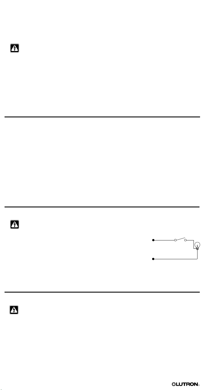
CAUTION! Before connecting the loads to the control unit, test the loads for short-circuits.
1. Turn power OFF at the circuit breaker or fuse box.
2. Connect a standard light switch between the live lead and load wire to
test the circuit.
3. Turn power ON and check for short or open circuits. If load does not
operate, the circuit is open. If the breaker/MCB trips (fuse blows or
opens), a load short may exist. Correct short or open circuits and test
again.
Hot/Live
Neutral
Step 2: Turn the Power OFF
CAUTION! Before continuing with the installation, make sure the power is turned OFF at
the circuit breaker or fuse box. Do not perform any wiring with the power ON.
Switch
Load
4 GRAFIK Eye® 3000 Series Control Unit Installer’s Guide
R
Step 3: Mount the Wallbox
230V
˜
LUTRON
5
0/6
0H
z
LO
AD
P
E
R
ZONE:
40 - 80
0
W
M
AX
UNIT LO
A
D: 1
0
A, 2300W
P
rese
t
Ligh
ting C
o
ntro
l
LIVE TERMINALS
AT
RE
AR
DO NOT WIRE LIVE
U.
K. 0
71
-70
2
-0657
U
.
S.
A
. (610) 282
-3
800
CO
O
PERS
B
UR
G
,
PA U
SA 18
0
36
GR
X-3104-
CE
UP
Ma
d
e in U
.S.A.
1
2V
S
E
LV
O
UTPU
T
!
CB
E
5
145-0
49
G
R
X
-Z
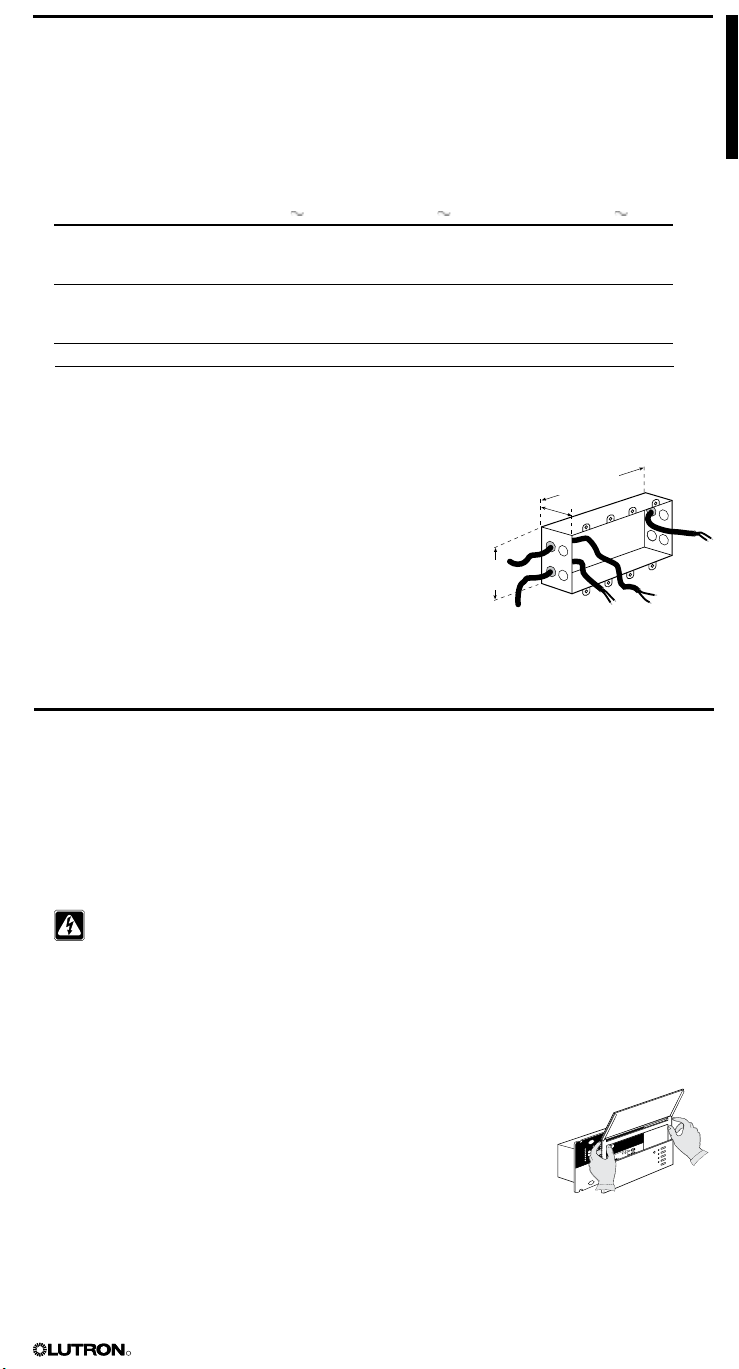
1. Mount a standard U.S. wallbox on a dry, flat indoor surface that is accessible and allows for
system programming and operation. See the table below for the recommended wallbox for
each model.
Use a minimum depth of 2 3/4 in. (68 mm), preferably 3 1/2 in. (87 mm). Allow at least 4 1/2 in.
(110 mm) clearance above and below the faceplate to ensure proper heat dissipation. Allow
1 in. (25
NOTE: For mounting in a panel, refer to page 10.
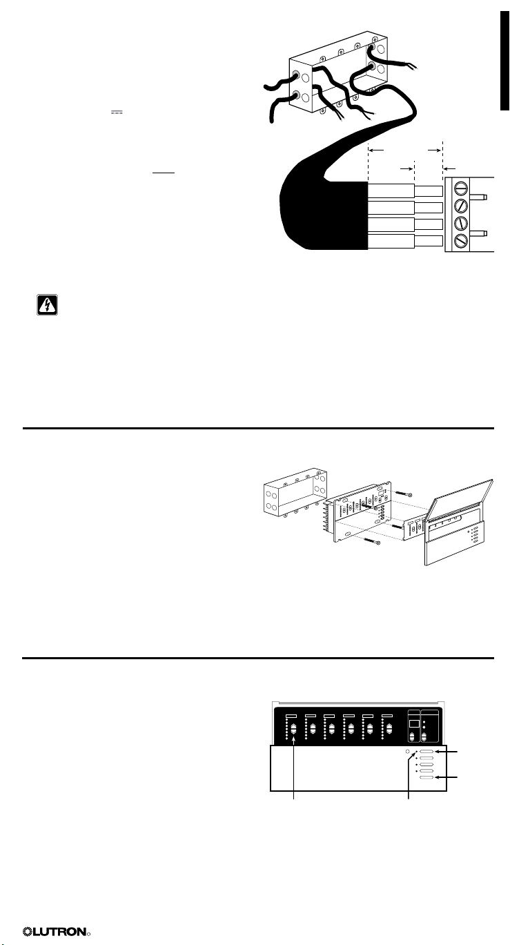
2. Pull the line voltage/mains cables into the wallbox using
If the control unit will be connected to wallstations and/
mm) for faceplate overhang on all sides.
Control Unit Model 100-120 V 230 V (CE) 220-240 V (AU)
GRX-3102/3502 2-gang wallbox 4-gang wallbox 2-gang wallbox
or two single-gang or two single-gang
wallboxes wallboxes
GRX-3103/3503 3-gang wallbox 4-gang wallbox 3-gang wallbox
or three single-gang or three single-gang
wallboxes wallboxes
GRX-3104/3504 4-gang wallbox 4-gang wallbox 4-gang wallbox
GRX-3106/3506 4-gang wallbox 4-gang wallbox 4-gang wallbox
NOTE: Single-gang wallbox P/N 241218; 4-gang wallbox P/N 241400.
7.9 in.
the rearmost knockouts. This will provide the most
clearance when mounting the control unit.
(87 mm)
(200 mm)
3.5 in.
or additional control units, also pull the PELV (Class 2:
USA) cabling into the wallbox using the remaining
rearmost knockout (refer to page 7). Use recommended
3.75 in.
(95 mm)
cable as specified in “PELV (Class 2: USA) Cables” on
page 3.
Step 4: Connect the Line Voltage/Mains Cables to the Control Unit
Important Wiring Information
• Use properly certified cable for all line voltage/mains cables.
• Proper short-circuit and overload protection must be provided at the distribution panel. You
can use up to a 20 A (16 A for AU, and 10 A for CE models) maximum circuit breaker/MCB or
equivalent (tripping curve C according to IEC60898/EN60898 is recommended) with adequate
short-circuit breaking capacity for your installation.
• Install in accordance with all local and national electrical codes.
CAUTION! Do not connect line voltage/mains cable to PELV (Class 2: USA) terminals.
• Earth/ground terminal connection must be made as shown in wiring diagrams on page 6.
• Do not mix different load types on the same zone!
• See page 3 for devices that require interfaces. Wire as specified in the interface documentation.
• The line voltage/mains cables should be separated from the PELV (Class 2: USA) cable and
terminal block by at least 1/4 in. (7 mm).
To connect the line voltage/mains cables to the control unit:
1. Remove the control unit’s cover and hinged faceplate by pulling
outward at each corner.
2. Strip 1/2 in. (12 mm) of insulation off the line voltage/mains cables in
the wallbox.
3. Connect the line voltage, ground, and load wires to the appropriate
terminals on the back of the control unit, as shown on page 6 for
GRX, GRX-AU and GRX-CE models.
The recommended installation torque is 9.0 in.-lbs. (1.0 N•m) for line voltage connections and
10 in.-lbs. (1.3 N•m) for the earth/ground connection. Each power terminal can accept up to
two #12 AWG (2.5 mm2 ) wires. This does not apply to the PELV (Class 2: USA) terminal block.
GRAFIK Eye® 3000 Series Control Unit Installer’s Guide 5
R
N
L
SSA
GRX-3106-CE
ZONE: 40 - 800 W/VA
10 A 2300 W/VA
Coopersburg, PA 18036 USA
:
ZONE 4
ZONE 6
HOT/LIVE
SSA
CU WIRE ONLY
ZONE 2
Class 2
1 2 3 4
ZONE 3
ZONE 5
NEUTRAL
ZONE 1
USA
CLASS 2
IEC
PELV
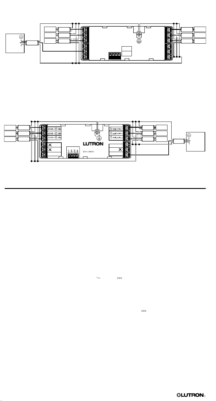
Line Voltage/Mains Connections for GRX* and GRX-AU* Models (6-Zone Unit Shown)
Earth/ground from distribution panel
Distribution
panel
Hot/
Live
N
2 #12 AWG
Input power from
distribution panel
Load 2
Load 4
Load 6
2 #12 AWG
2 #12 AWG
2 #12 AWG
2 #12 AWG
2 #12 AWG
2 #12 AWG
Neutral from distribution panel
Line Voltage/Mains Connections for GRX-CE Models* (6-Zone Unit Shown)
Earth/ground from distribution panel
Load 1
Load 3
Load 5
Load 2
Load 4
Load 6
2 2.5 mm
2 2.5 mm
2
2
2
2 2.5 mm
* For phase-to-phase and delta-feed wiring, contact Lutron.
2
2 2.5 mm
Load 1
2
2 2.5 mm
Load 3
2
2 2.5 mm
Load 5
Neutral from
distribution panel
Input power from
distribution panel
Distribution panel
Hot/
2
2 2.5 mm
Live
N
Step 5: Connect PELV (Class 2: USA) Cable to the
Control Unit — Optional
If your lighting system uses wallstations and/or multiple control units, PELV (Class 2: USA)
wiring is needed to supply power and carry communications between the control units and the
wallstations.
Important Wiring Information
• Lutron requires that you connect (daisy-chain) control units and wallstations with two twisted
pairs for operation. Each twisted pair in the PELV (Class 2: USA) wiring link should consist of
two #18 AWG (1.0 mm2) stranded conductors.
• Use properly certified PELV (Class 2: USA) cable. For a description of recommended cable
types, refer to “PELV (Class 2: USA) Cables” on page 3.
• Install in accordance with all local and national electrical codes.
• Wallstation circuits are classified as Class 2 (USA) and PELV (IEC) circuits. Unless otherwise
specified, the voltages do not exceed 24 V or 15 V . As Class 2 circuits, they comply
with the requirements of NFPA 70®, National Electrical Code® (NEC®). As PELV circuits, they
comply with the requirements of IEC 60364-4-41, VDE 0100 Part 410, BS7671:1992, and other
equivalent standards. External circuits connected to input, output, RS232, Ethernet, DMX512,
and other communication terminals or wallstations, must be supplied from a Listed Class 2
source or comply with the requirements for PELV circuits as applicable in your country.
• The control unit’s low-voltage PELV (Class 2: USA) circuit is 12 V .
• The PELV (Class 2: USA) cable and terminal block should be separated from the line voltage/
mains cables by at least 1/4 in. (7 mm).
6 GRAFIK Eye® 3000 Series Control Unit Installer’s Guide
R
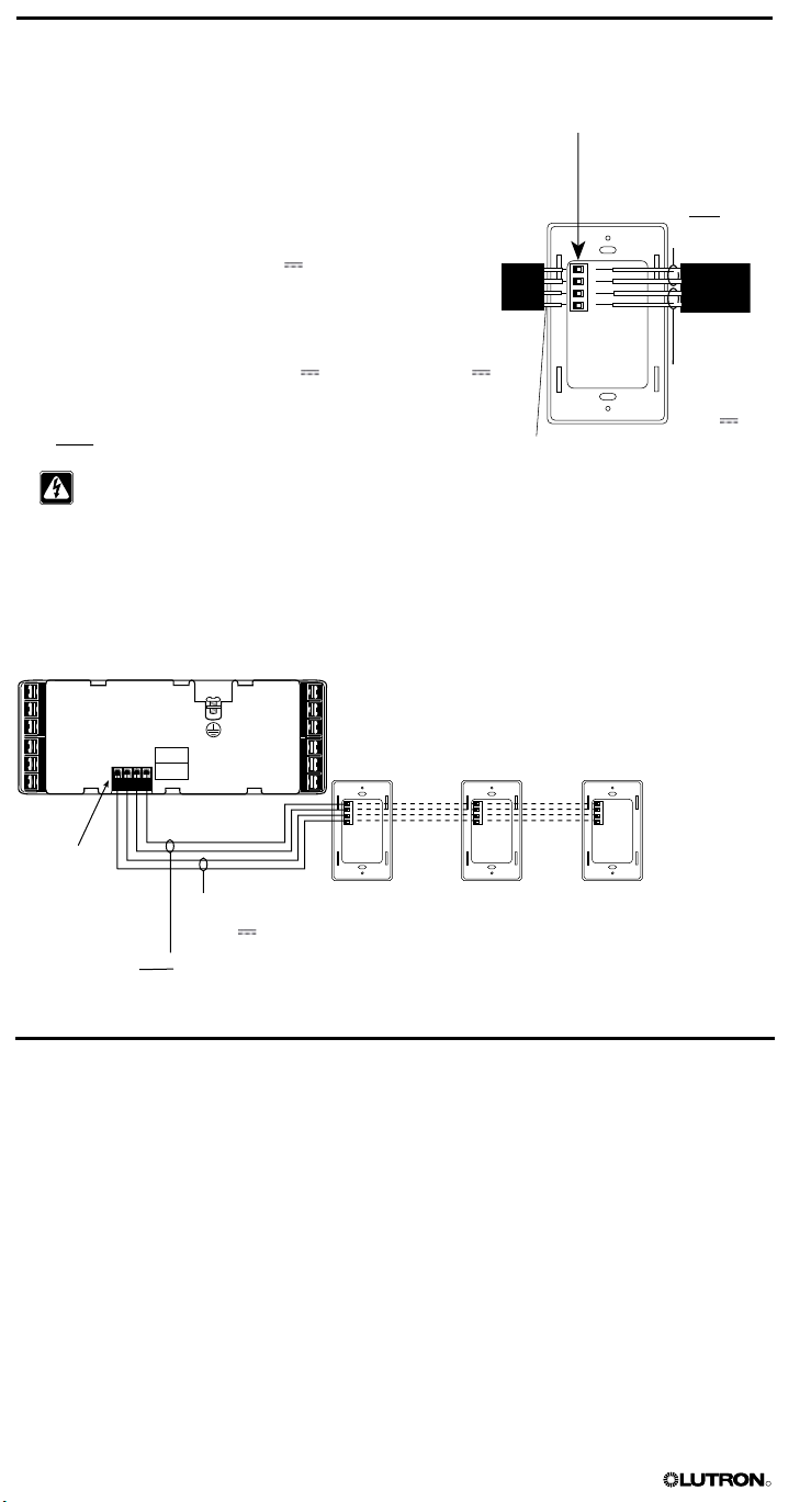
To connect the PELV (Class 2: USA) wires to the control unit:
1
2
3
4
M S
FADE TEMPORAR Y
MASTER
ZONES
ZONE 5 ZONE 6ZONE 3 ZONE 4ZONE 1 ZONE 2
1. Strip 1 in. (25 mm) of insulation from the
PELV (Class 2: USA) cable in the wallbox.
2. Strip 3/8 in. (9.5 mm) of insulation from each
wire.
3. Connect the twisted pair for low-voltage
power wiring to terminal 1 (common) and
terminal 2 (12 V ) on the control unit.
NOTE: You will daisy-chain this low-voltage
power wiring to wallstations and/or other
Line voltage/mains
cable
control units. Refer to pages 8 and 9.
4. Connect the twiste
d pair data link to terminal
3 (MUX) and terminal 4 (MUX) of the control
unit.
NOTE: You will daisy-chain this data link to
wallstations and/or other control units. Refer
to pages 8 and 9.
5. If shielded wire is used, connect the drain
wires to each other or to terminal D on the
wallstation, if present. Do NOT connect drain
2 pair #18 AWG
(1.0 mm2)
wires to earth/ground.
WARNING! Make sure no bare wire
is exposed after making connections.
The recommended installation torque is
3.5 in.-lbs. (0.4 N•m) for PELV (Class
2: USA) connections.
Line voltage/mains
cable
PELV (Class 2:
USA) cable
1.0 in.
(25 mm)
3/8 in.
(9.5 mm)
PELV (Class 2:
USA) terminals
Step 6: Mount the Control Unit
1. Mount the control unit in the wallbox as shown
using the four screws provided.
NOTE: Make sure the PELV (Class 2: USA)
cable and terminal block remain separated
from the line voltage/mains cables when the
control unit is mounted in the wallbox.
2. Reattach the cover and faceplate to the
control unit by pushing inward at each corner.
Step 7: Test the Control Unit
1. Turn the power ON.
2. Press the SCENE 1 button on the front of the
control unit. The Scene 1 LED will light.
3. Press the 5 or 6 button for each zone and
verify that the control unit is controlling all
connected loads. If not, refer to Appendix
A: Troubleshooting, or call Lutron Technical
Support.
ZONE intensity
raise
and lower
buttons
Scene 1 LED
SCENE 1
button
OFF
GRAFIK Eye® 3000 Series Control Unit Installer’s Guide 7
R
Step 8: Connect the Wallstations — Optional
4
3
2
1
4
3
2
1
4
3
2
1
4
3
2
1
ZONE 4
ZONE 6
HOT/LIVE
SSA
CU WIRE ONLY
ZONE 2
Class 2
1 2 3 4
ZONE 3
ZONE 5
NEUTRAL
ZONE 1
USA
CLASS 2
IEC
PELV
If your lighting system uses wallstations, make the appropriate connections at the wallstation
using PELV (Class 2: USA) cabling.
NOTE: For procedures on how to install and address
wallstations, refer to the separate instructions included with
each device. Wallstations must be installed by a qualified
electrician in accordance with all local and national electrical
codes.
1. Daisy-chain the PELV (Class 2: USA) twisted pair for low-
voltage power wiring from the control unit to terminal
1 (common) and terminal 2 (12 V ) on up to three
wallstations.
2. Terminate the terminal 2 connection so that the control unit
supplies power to a maximum of three wallstations.
NOTE: To power more than three wallstations from one
control unit, install an external 12 V power supply (15 V
for CE/AU models). Refer to page 10 for instructions.
3. Daisy-chain the PELV (Class 2: USA) twisted pair data
link from the control unit to terminal 3 (MUX) and terminal
4 (MUX) on each wallstation.
WARNING! Make sure no bare wire is exposed after
making connections. The recommended installation
torque is 3.5 in.-lbs. (0.4 N•m) for PELV (Class 2: USA)
connections.
Control Unit Connected to Three Wallstations
GRAFIK Eye
3000 control unit
Each terminal can accept
2 #18 AWG (1.0 mm2) wires
2 twisted pairs
#18 AWG
(1.0 mm2)
Data link:
4: MUX
3: MUX
PELV
(Class 2: USA)
power
2: 12 V
1: common
wiring:
Wallstation Wallstation Wallstation
Each
terminal
can accept
2 #18 AWG
(1.0 mm2)
wires
Data link:
4: MUX
3: MUX
PELV (Class 2: USA)
power wiring:
2: 12 V
1: common
Maximum of 1000 ft. (300 m) between the
GRAFIK Eye control unit
and the third wallstation.
For longer distances or to power more than three
wallstations, see page 10.
Step 9: Connect Other Accessories — Optional
If your lighting system uses accessories other than wallstations (shade controllers, interface
devices, and power boosters), make the connections at the accessory using the appropriate
wiring.
For procedures on how to install and connect accessories, refer to the separate instructions
provided with each accessory.
Important Wiring Information
• Accessories must be installed by a qualified electrician in accordance with all local and national
• Use properly certified cable as described in the instructions shipped with the accessory.
electrical codes.
8 GRAFIK Eye® 3000 Series Control Unit Installer’s Guide
R
4
3
2
1
4 3 2 1
1 2 3 4
1 2 3 4
4 3 2 1
4
3
2
1
4
3
2
1
4
3
2
1
4
3
2
1
4
3
2
1
4
3
2
1
4
3
2
1
4
3
2
1
4
3
2
1
4
3
2
1
4
3
2
1
4
3
2
1
4
3
2
1
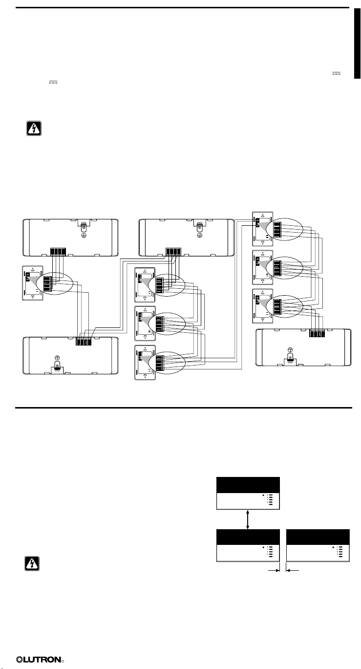
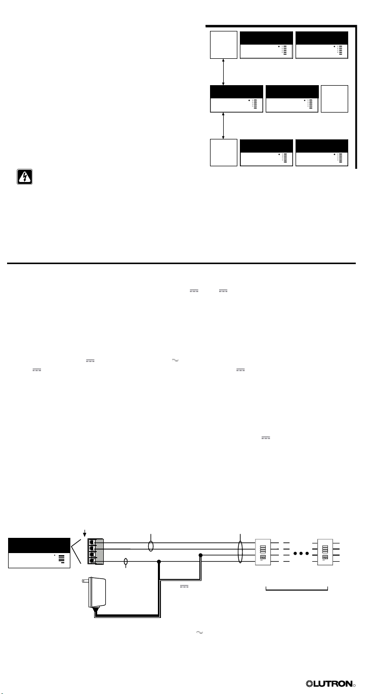
Step 10: Connect Multiple Control Units — Optional
If your lighting system has multiple control units, connect them using PELV (Class 2: USA)
cabling as described here.
1. Daisy-chain the PELV (Class 2: USA) cabling to terminal 1, terminal 2, terminal 3, and terminal 4
on all control units and wallstations.
NOTE: To power more than three wallstations from one control unit, install an external 12 V
or 15 V power supply. Refer to page 10 for instructions.
2. Since each control unit has its own power supply, terminate the terminal 2 connection so that:
• Each control unit supplies power to a maximum of three wallstations.
• Each wallstation receives power from only one control unit.
WARNING! Make sure no bare
mended installation torque is 3.5 in.-lbs. (0.4 N•m) for PELV (Class 2: USA) connections.
System Maximums: Up to 8 Control Units and 16 Wallstations
and 8 Shade Controllers
A1
a
A2 and A3
have their
own power
supplies—no
inal 2
A1 powers a only—
terminal 2 connection
terminates at a.
term
connection.
wire is exposed after making connections. The recom-
Total PELV (Class 2: USA)
A3
b
c
e
f
A3 powers b, c and d.
g
ing length is 2000 ft.
wir
(600 m).
A4 powers
e, f, and
g—
no
terminal 2
connection
between d
and e.
A2
d
Special Mounting Considerations
Wallbox Mounting and Spacing
When mounting multiple control units or interface devices, be sure to follow spacing and
ventilation requirements to ensure proper operation.
• All control units MUST be mounted in a standard
U.S. wallbox. (For mounting procedures, refer to
A4
page 5.)
• All control units, power boosters, fluorescent
interfaces, and electronic low-voltage interfaces MUST
have 4 1/2 in. (110 mm) of space above and below
the faceplate to dissipate the heat caused by normal
operation. Allow 1 in. (25 mm) for faceplate overhang
on all sides.
CAUTION! GRAFIK Eye 3000 Series control
units and interface devices, such as NGRX-PB,
dissipate heat when operating. Obstructing
these units can cause malfunction to both the
control unit and the interface device if ambient
temperature does not remain between 32–104 °F
(0–40 °C).
GRAFIK Eye® 3000 Series Control Unit Installer’s Guide 9
4 1/2 in. (110 mm) minimum
Limited by physical size of unit.
Must be able to open front cover.
R
4
3
2
1
4
3
2
1
3
2
1
4
Mounting in a Panel
• The enclosure must be in accordance with all local
and national electrical codes.
• Lutron does not recommend using a door to enclose
the front of a panel, since this restricts airflow to the
ELV
interface
control units and interface devices.
• If mounting multiple control units or interface devices
4 1/2 in. (110 mm) minimum
in an enclosure:
– Ambient temperature within an
enclosure MUST
remain between 32–104 °F (0–40 °C).
– If not mounting in a metal enclosure, all units
MUST be mounted in a wallbox. Refer to
4 1/2 in. (110 mm) minimum
FDB
interface
“Wallbox Mounting and Spacing” on page 9.
• To improve heat dissipation of interface units, (i.e.,
NGRX-PB, GRX-ELVI, etc.), remove the faceplate
Power
booster
from the unit.
CAUTION! GRAFIK Eye 3000 Series control
d interface devices, such as NGRX-PB,
units an
dissipate heat when operating. Obstructing
these units can cause malfunction to both the
control unit and the interface device if ambient
temperature does not remain between 32–
104 °F (0–40 °C).
Installing an External Power Supply
Install an external PELV (Class 2: USA) rated 12 V (15 V for CE/AU models) power supply if
you need to power 4 to 16 wallstations from a single control unit or if your wire lengths exceed
maximums. The power must be a regulated supply rated for at least 50 mA per wallstation on
the link.
Power supplies do not boost data line signals. The distance limitation for the data line is 2000 ft.
(610 m).
Make sure you review the manufacturer’s instructions before installing.
Lutron offers a 12 V
15 V power supply is approved for CE and AU models; 12 V is approved for all other
models.
Important Wiring Information
1. Connect the Common and Power wires from the power supply to Terminals 1 and 2 on all
wallstations. Do not connect this wire to any control units on the link. Be sure that the terminal 1
connection is made to all wallstations and control units.
2. Lutron recommends these maximum distances from the external 12 V power supply to the
sixteenth wallstation:
• #18 AWG (1.0 mm
• #12 AWG (2.5 mm
Note that the allowable maximum distance depends on the number of wallstations in the system.
Refer to separate Application Note W14 or contact Lutron Technical Support for additional
information.
transformer for 120 V applications. Please ask for P/N GRX-12VDC.
2
) wire: 300 ft. (90 m).
2
) wire: 1000 ft. (300 m).
PELV (Class 2: USA) terminals
on back of unit
To power source
10 GRAFIK Eye® 3000 Series Control Unit Installer’s Guide
1 twisted pair
#18 AWG (1.0
or larger
1 #18 AWG
(1.0 mm2)
External PELV (Class 2:
Lutron P/N GRX-12VDC for 120 V applications
UK plug style TU-240-15DC-9-BL
European plug style
mm2)
Common
12 V
USA) rated power supply
TE240-15DC-9-BL
2 twisted pairs
#18 AWG (1.0
mm2) or larger
Wallstation Wallstation
16 wallstations
(maximum)
R
Section 3:
FADE TEMPORARY
MASTER
ZONES
ZONE 5 ZONE 6
M S
FADE TEMPORARY
MASTER
ZONES
ZONE 1 ZONE 2
M S
00
Programming a GRAFIK Eye® Control Unit
This section identifies buttons and indicators on a GRAFIK Eye 3000 Series control unit. This
section also explains how to enter setup mode, program a control unit, adjust the high and low
end trim, and select a save mode. Most programming operations are typically performed only
once, when the control unit is installed. Other operations, such as selecting scenes and making
temporary adjustments, are performed as needed to achieve the right lighting and shade effects.
For systems with multiple control units, refer to page 20 for addressing.
NOTE: Lutron ships each control unit with factory-set programming. For a description of the
factory presets, refer to page 3
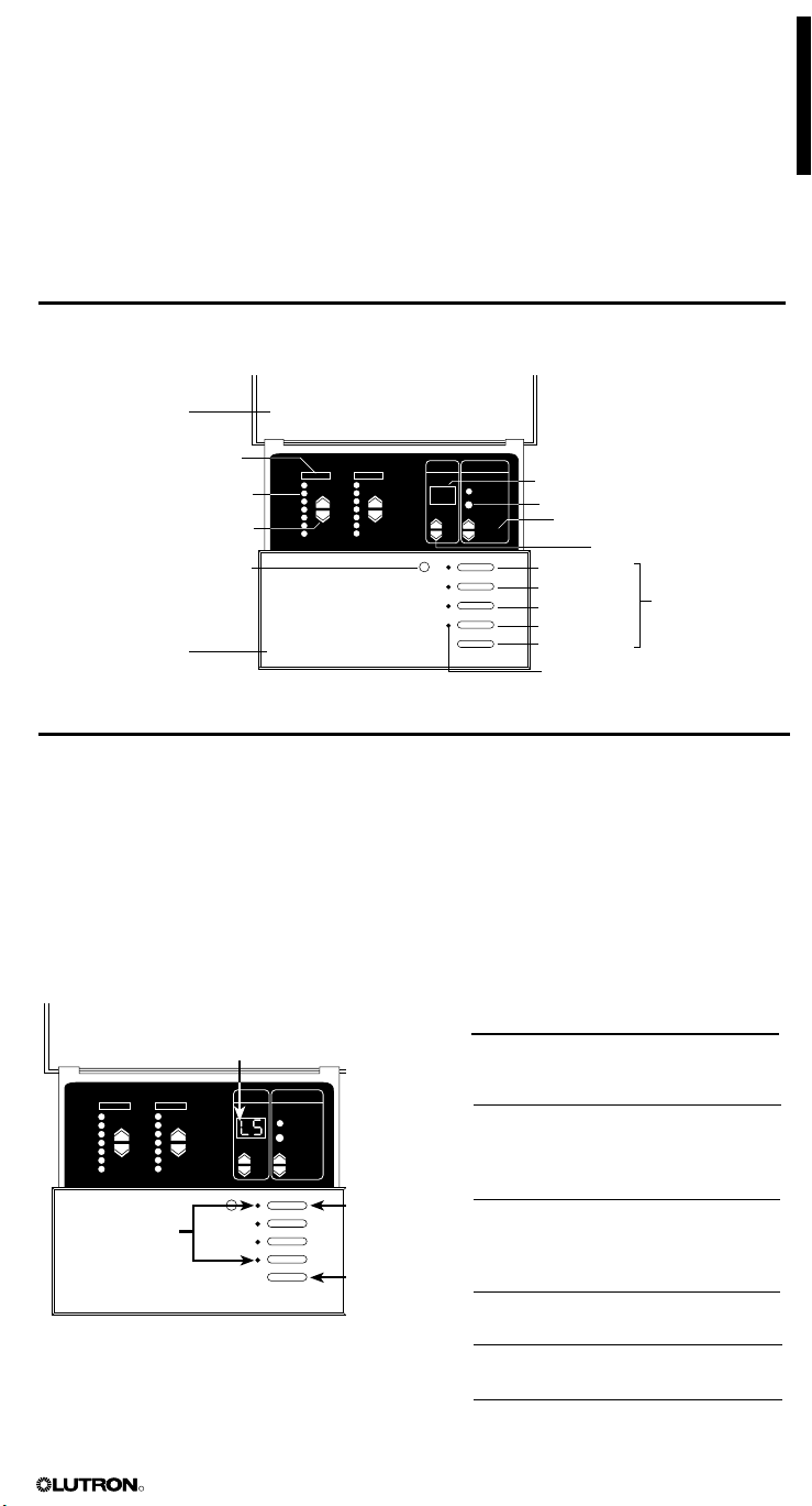
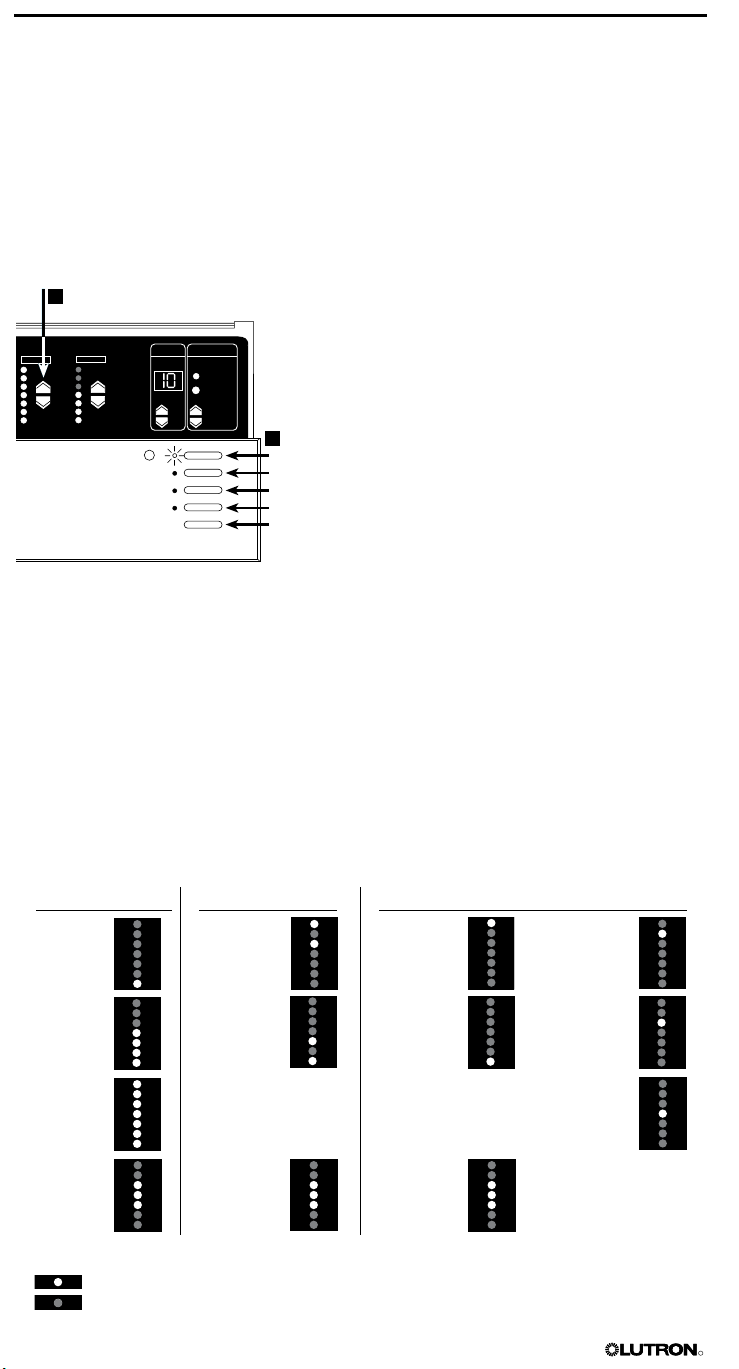
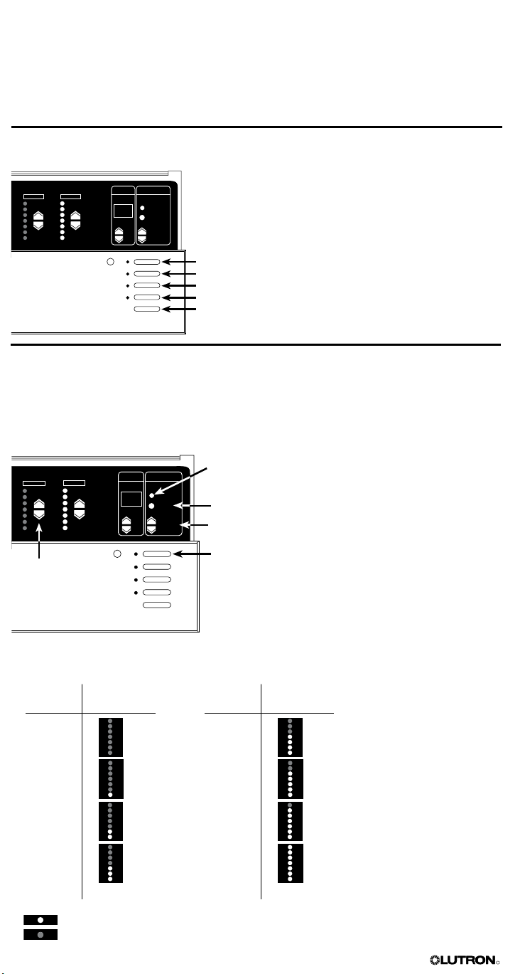
Control Unit Buttons and Indicators
Hinged cover
Zone label
Light level/shad
ZONE raise/lower buttons
remote
Faceplate
e position
LED bar graph
Infrared wireless
control receiver
Scene
FADE window (if
in seconds, if ‘M’ is lit, time is in
minutes)
TEMPORARY
MASTER raise/lower buttons
Scene 1
Scene 2
Scene 3
Scene 4
OFF
indicator LEDs
‘S’ is lit, time is
ZONES button
FADE buttons
SCENE buttons
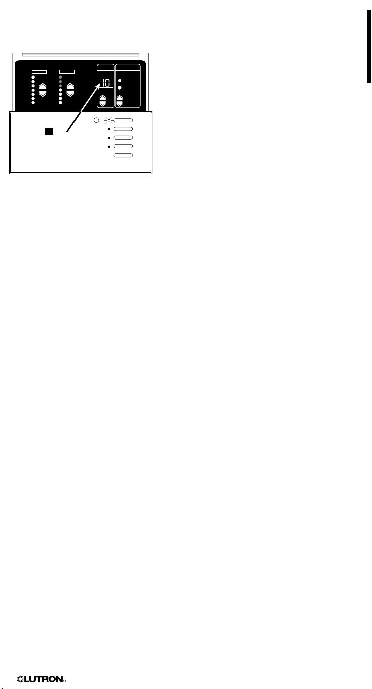
Entering and Exiting Setup Mode
You must enter setup mode to access the programming functions on the control unit.
To enter setup mode: Press and hold the SCENE 1 and OFF buttons for about three sec-
onds, until the scene LEDs start cycling. When the buttons are released, the LEDs should
continue to cycle.
In setup mode, the FADE window displays the first setup code available for programming. To
scroll up and down through the menu of setup codes, press the FADE 5 or 6buttons.
To exit setup mode: Press and hold the SCENE 1 and OFF buttons for about three seconds,
until the scene LEDs stop cycling. The control unit returns to normal operating mode.
The setup codes include:
Use 5
codes (LS is the first code to display)
Scene LEDs
to scroll through setup
and 6
To enter (exit)
setup mode:
Press and
hold for
about three
seconds until
LEDs cycle
(stop cycling)
Code Stands for Description
Sd Save modes Select from
several save
options (page 17).
Sc Scene Set up any of the
scenes, including
unaffected zones
(page 16).
A- Address Identify control
units for system
communications
(page 20).
LS Load Select Identify load types
(page 12).
HE High End Set high end trim
(page 17).
LE Low End Set low end trim
(page 17).
GRAFIK Eye® 3000 Series Control Unit Installer’s Guide 11
R
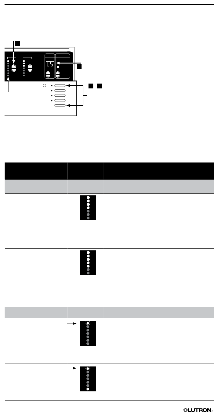
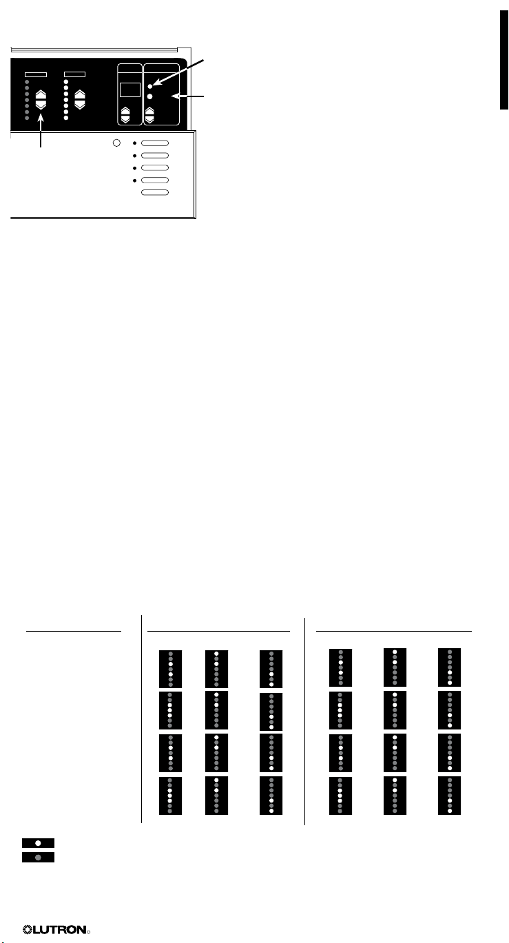
Identifying the Load Type for Each Zone
FADE TEMPORARY
MASTER
ZONES
ZONE 5 ZONE 6
M S
3
2
1 4
,
A load refers to the type of lighting, shade, or interface device connected to the control unit.
Lutron ships control units with all zones set for incandescent/halogen (tungsten) lighting. If your
lighting system has non-incandescent loads, change each of those zones to the correct load type.
Set the load type for each zone
Check for
LS
Zone LEDs
To set this load type...
Enter
(exit)
setup
mode
Select this
LED display Important Notes
Switching (non-dim)
Loads
Non-dim
*
(last on, first off)
Non-dim
* Use non-dim for
(first on, first off)
Motorized Shades
AC shade* * AC
Sivoia
® QED
shade*
Blinking
LED
Blinking
LED
* Sivoia QED shade zones are factory set to
To identify the load type for each zone:
1. Enter setup mode. Press and hold the
SCENE 1 and OFF buttons for about three
seconds, until the scene LEDs cycle.
2. Check for LS in FADE window. LS is the
first code to display when you enter setup
mode. In LS mode, ZONE LEDs turn on from
top to bottom.
3. Set the load type for each zone. Press the
ZONE 5 or 6 button until the ZONE LEDs
match the load type connected to each zone.
Refer to the following table for each load type
and its corresponding LEDs.
4. Exit setup mode. Press and hold the SCENE
1 and OFF buttons for about three seconds,
until scene LEDs stop cycling.
In the sample 6-zone control unit shown here:
• Zone 5 is set for incandescent, magnetic
low-voltage, or HP dimming module.
• Zone 6 is set for neon/cold cathode.
Use non-dim for any lights to be switched ON and
OFF only—not dimmed (unless using HP dimming
module) when fading between scenes. This load will
be the last to switch on and the first to switch off.
Fluorescent non-dim loads with electronic or magnetic ballasts must use a GRX-TVI Interface and
be set for non-dim mode, or use an HP 2•4•6TM
dimming module and be set for HP 2•4•6
dimming module loads. Contact closure outputs.
any lights to be switched ON
and OFF only—not dimmed (unless using HP
dimming module) when fading between scenes.
This load will be the first to switch on and the first
to switch off.
Fluorescent non-dim loads with electronic or magnetic ballasts must use a GRX-TVI Interface and
be set for non-dim mode, or use an HP 2•4•6
dimming module and be set for HP 2•4•6
dimming module loads. Contact closure outputs.
shades zones
are factory set to unaffected
in each scene. To program shade positions for a
scene, refer to pages 14 and 15.
GRAFIK Eye 3000 control units must be
addressed to control shades. To assign
addresses, refer to page 20.
unaffected in each scene. To program shade
positions for a scene, refer to pages 14-16.
GRAFIK Eye 3000 control units must be
addressed to control shades. To assign
addresses, refer to page 20.
12 GRAFIK Eye® 3000 Series Control Unit Installer’s Guide
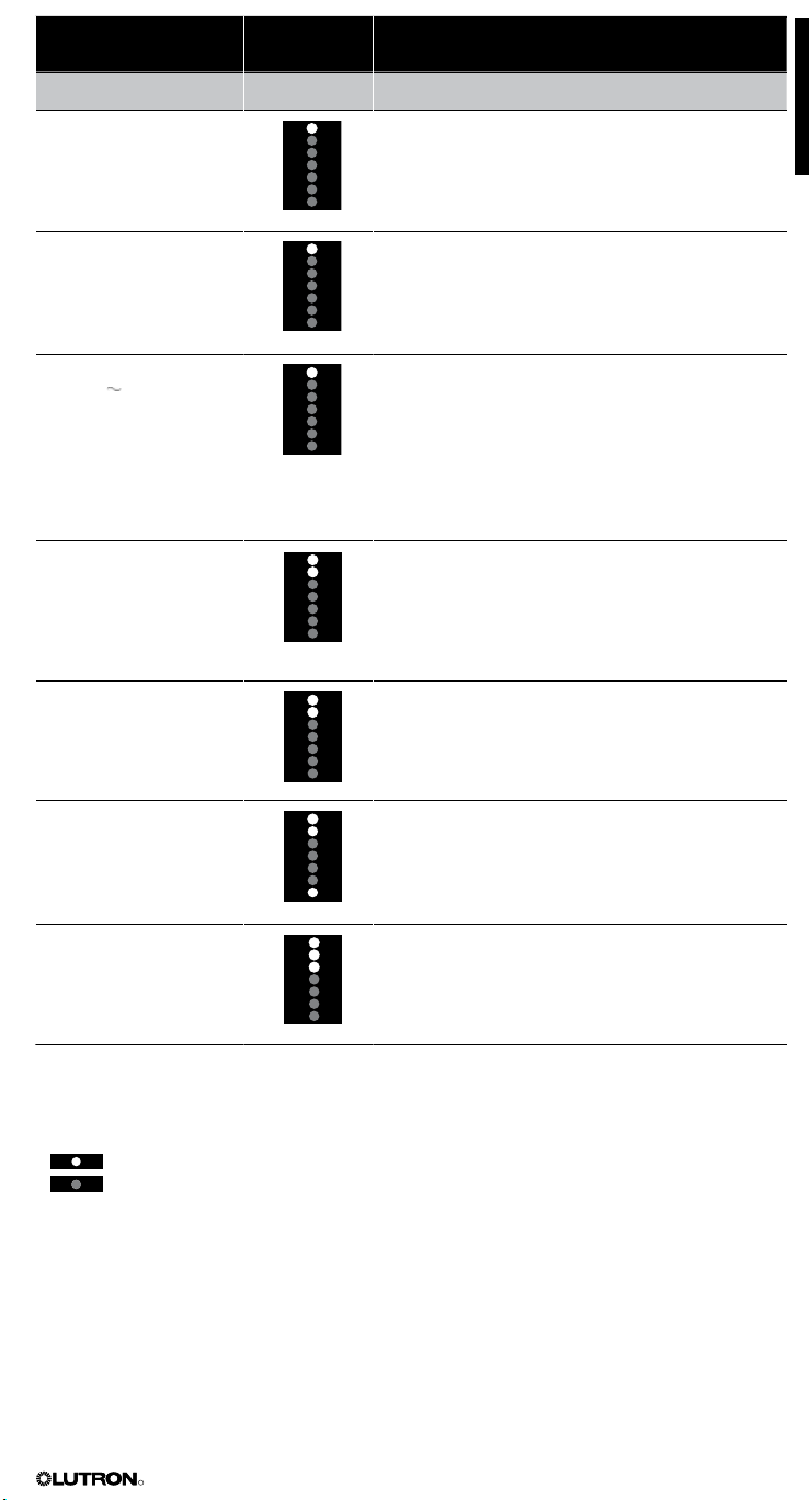
R
To set this load type...
Dimming Loads
Incandescent/halogen
(tungsten)
Select this
LED display Important Notes
* Use for tungsten
NOTE: This is the factory preset load type for each
zone.
filament lamps.
Magnetic low-voltage * Use for magnetic
•4•6TM loads
HP 2
(120 V supply only)
* Set all zones connected to HP dimming modules
as shown—no matter what load type they are
(including non-dim or switching). The HP can be
used to switch non-capacitive ballasts. To finetune the dimming of these “HP-powered” zones,
you must adjust high and low end trim on the HPs
as described in the instructions supplied with the
unit. Do NOT use HPs with generator-supplied
line/mains voltage.
GRX-ELVI loads
(Electronic
low-
voltage)*
* All electronic low-voltage (ELV) lighting used with
an electronic low-voltage interface (ELVI) must
be rated for reverse phase control/trailing edge
dimming. Refer to the documentation for your
interface.
GRX-FDBI or
GRX-TVI loads
(Lutron 3-wire
fluorescent)*
* Zones
fluorescent lighting must have GRX-FDBI or
GRX-TVI fluorescent interfaces. Contact Lutron
for more information. Refer to the documentation
set for Lutron Hi-lume or Eco-10
for your interface.
Tu-Wire® compact
fluorescent
* Tu-Wire compact fluorescent does not require a
fluorescent dimming ballast interface (FDBI). This
load type is not available in GRX-CE models.
transformer low-voltage lighting.
Neon/cold cathode * Use for neon or cold cathode lighting.
*Interface required; contact Lutron Technical Support for details.
Legend:
LED lit
LED off
GRAFIK Eye® 3000 Series Control Unit Installer’s Guide 13
R
Programming Scenes
FADE TEMPORARY
MASTER
ZONES
ZONE 5 ZONE 6
ZONE
M S
2
1
Scenes are preset lighting levels, fade times, and shade positions stored in the control unit. (Note
that AC shades can be programmed in a scene as only fully open, fully closed, or unaffected;
Sivoia QED shades can be programmed at any preset level or unaffected.) You can program up
to 16 scenes, plus OFF (scene 0). Any time a scene button is pressed or input from an optional
control interface is received, the system activates the desired scene.
Programming Scenes 1 through 4 (Save Mode)
If the control unit is set to the factory default Sd save mode (adjustments to zone settings are
saved for the current scene), you can program scenes 1 through 4 without entering setup mode.
NOTE: To program scenes using setup mode, refer to page 16. To select a save mode, refer to
page 17.
Set the scene settings for each zone
To program scenes 1 through 4 using
save mode:
1. Select a scen
scene you want to pro
e. Press the SCENE button for the
gram.
2. Set the scene settings for each zone.
For lighting zones, press the ZONE 5 or 6
Select a
scene
Scene 1
Scene 2
Scene 3
Scene 4
OFF
button to set the right visual intensity for this
scene.
For AC shade zones, press the ZONE 5 or 6
button until the ZONE LEDs match the right
shade position for this scene. See the illustration
below.
For Sivoia QED shade zones, press the
ZONE 5 or 6 button until the ZONE LEDs
match the right shade position for this scene.
See the illustration below.
NOTE: To quickly set a shade zone to fully open
or fully closed, press and hold the ZONE 5 or 6
button for about three seconds.
unaffected zones, press and hold the
For
ZONE 6 button until all its LEDs go out and
the middle three LEDs light (this may take up
to 10 seconds). This zone’s settings will not be
affected when this scene is selected.
To reprogram an unaffected zone as
affected, follow the steps above. Then press the
ZONE 5 button for about three seconds until
the middle three ZONE LEDs are no longer lit.
Program the zone’s settings.
LED Displays for Programming Scene Settings
Lighting Zones AC Shade Zones Sivoia QED Shade Zones
Off Fully open Fully open Preset 1
On 50% Fully closed Fully closed Preset 2
On 100% Preset 3
Unaffected Unaffected Unaffected
Legend:
LED lit
LED off
14 GRAFIK Eye® 3000 Series Control Unit Installer’s Guide
R
FADE TEMPORARY
MASTER
ZONES
ZONE 5 ZONE 6
ZONE
M S
3
Set scene’s
fade-in time
3. Set the fade-in time for this scene (does not
apply to shades). Press the FADE 5 or 6 button
to make the fade-in time anything from 0–59
seconds or 1–60 minutes.
The M and S indicators under the FADE window
show whether fade is “M”inutes or “S”econds.
To set the fade in minutes, press the FADE 5
button to scroll through 1–59 seconds to 1 to 60
minutes, then M lights. Fade is now expressed
in minutes. To get back to seconds, press
the FADE 6 button until the window shows
“S”econds.
4. Repeat steps 1 through 3 to set up each of the
remaining scenes.
To set a Fade-to-OFF time, press the OFF
scene button, then set the seconds or minutes to
fade to OFF from this scene.
GRAFIK Eye® 3000 Series Control Unit Installer’s Guide 15
ZONE 1 ZONE 2
M S
2
3
4
1
FADE TEMPORAR Y
MASTER
ZONES
5
6
,
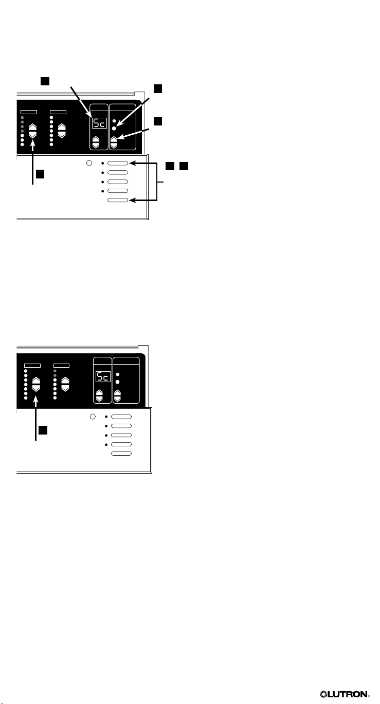
Programming Scenes 1 through 16 (Setup Mode)
ZONE 5 ZONE 6
M S
FADE TEMPORAR Y
MASTER
ZONES
4
R
You can program any scene using setup mode. If your lighting system requires more than 4
scenes, scenes 5 through 16 must be programmed using setup mode.
NOTE: To program scenes 1 through 4 using Sd save mode, refer to page 14.
Select flashing Sc/1
Program
lighting or
shade scene
settings for
each zone
To set unaffected zone,
press ZONE 6 twice
and then hold until middle three LEDs light
Set scene’s
fade-in time
Select
scene
Enter
(exit)
setup
mode
To program scenes using setup mode:
1. Enter setup mode. Press and hold the
SCENE 1 and OFF buttons for about
three seconds until the scene LEDs start
cycling.
2. Select Sc (scene setup) by pressing the
FADE 5 button twice. Sc and 1 (scene 1)
will alternately flash in the FADE window.
3. Select scene. Press the MASTER 5
or 6 button to select the number of the
scene to be programmed (1 through 15;
0 is the OFF scene).
4. Program scene settings for each zone.
For lighting zones, press the ZONE 5
or 6 button to set the zone intensity.
(GRX-3500 units will display exact percentage light output; press again to adjust
light levels in 1% increments.)
For AC shade zones, press the
ZONE 5 or 6 button until the ZONE
LEDs match the right shade position for
this scene. See the illustration on page 14.
For Sivoia QED shade zones, press
the ZONE
5 or 6 button until the ZONE
LEDs match the right shade position for
this scene. See the illustration on page 14.
For unaffected zones, press and hold
the ZONE 6 button until all its LEDs go
out and the middle three LEDs light (this
may take up to 10 seconds). This zone’s
settings will not be affected when this
scene is selected.
To reprogram an unaffected zone as
affected, follow the steps above. Then
press the ZONE 5 button for about three
seconds until the middle three ZONE
LEDs are no longer lit. Program the
zone’s settings.
5. Set the scene’s fade-in time. Press
and hold the TEMPORARY ZONES
button. The current fade-in time will be
displayed. Adjust using the FADE 5 or 6
button while still holding the TEMPORARY
ZONES button. (Fade time does not apply
to shade zones.)
6. Exit setup mode. Press and hold the
SCENE 1 and OFF buttons until the LEDs
stop cycling.
16 GRAFIK Eye® 3000 Series Control Unit Installer’s Guide
Adjusting High or Low End Trim
FADE TEMPORARY
MASTER
ZONES
ZONE 5 ZONE 6
M S
3
2
1
4
,
FADE TEMPORARY
MASTER
ZONES
ZONE 5 ZONE 6
M S
2
3
1
4
,
R
High and low end trim settings limit the maximum and minimum output of a dimming zone. Trim
levels are set automatically when the load type is programmed. Change the high or low end trim
for a zone only if the default setting needs to be adjusted.
Adjust zone’s trim setting
The zone’s LED bar graph does
not change while you make trim
adjustments. The bar graph
remains set to its highest/lowest
level in this mode.
Select HE
or LE
Enter
(exit)
setup
mode
To adjust high or low end trim:
1. Enter setup mode. Press and hold the
SCENE 1 and OFF buttons for about three
seconds, until the scene LEDs start cycling.
2. Select HE (high end) or LE (low end).
Press the FADE 6 button until HE or LE is
displayed in the FADE window.
For high end, all zones go to their highest
possible dim levels and all their LEDs are lit.
For low end, all zones go to their lowest possible
dim levels and only their bottom LED is lit.
NOTE: For shade zones, the middle three LEDs
are lit to indicate that they are unaffected. For
non-dim lighting zones, all LEDs are lit (for
high end) or OFF (for low end) and you cannot
adjust the high or low end trim.
3. Adjust zone’s trim setting. Press the
ZONE 5 or 6 button to raise or lower the
trim. Repeat this process for other zones that
require trim adjustments.
4. Exit setup mode. Press and hold SCENE 1
and OFF buttons until the scene LEDs stop
cycling.
Note: Setting low-end trim below the factory
default may cause some load types to flicker.
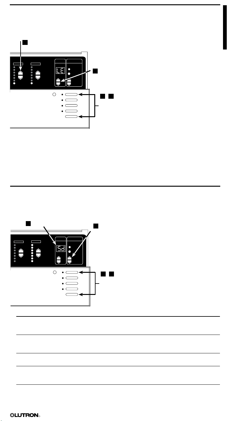
Selecting the Save Mode You Want to Use
Save modes enable you to specify how buttons on the control unit work. For example,
adjustments to a zone’s settings can be temporary or saved for the current scene. Buttons can
also be disabled to prevent accidental changes.
Select Sd
Code Stands for Description
Sd
Sb
Sn
4S
bd
Save by Default
Save by Button TEMPORARY ZONES LED is normally ON and all intensity/shade position and
Save Never
Four Scenes
Button Disable
Changes to a zone’s intensity/shade position or fade time are saved for
Allows only the four SCENE buttons, OFF button, IR receiver, and
All buttons on the control unit are disabled. IR receiver and wallstations are
Select
save mode
Enter
(exit)
setup
mode
the current scene. To make temporary adjustments in Sd mode, refer to
page 18. Typical user: Home theater owner.
fade changes are temporary unless the TEMPORARY ZONES LED is turned
OFF with the TEMPORARY ZONES button. Typical user: Restaurant manager.
TEMPORARY ZONES LED is permanently ON and cannot be turned OFF. In
this mode, all intensity changes are temporary. Typical user: Lighting designer.
MASTER 5 or 6 buttons to operate. All other buttons on the control unit
are disabled. Typical use: Rented meeting space.
still functional. (Setup mode is still accessible by repeating Step 1.) Typical
use: Public space.
To select the save mode you want to use:
1. Enter setup mode. Press and hold the
SCENE 1 and OFF buttons for about three
seconds until scene LEDs start cycling.
2. Select Sd. Press the FADE 5 button until
Sd is displayed in the FADE window.
3. Select save mode. Press the MASTER 5
or 6 button to scroll through the save
modes and select one. Refer to the save
mode descriptions in the table below.
4. Exit setup mode. Press and hold the
SCENE 1 and OFF buttons until scene LEDs
stop cycling.
GRAFIK Eye® 3000 Series Control Unit Installer’s Guide 17
FADE TEMPORARY
MASTER
ZONES
ZONE 5 ZONE 6
M S
Section 4:
FADE TEMPORAR Y
MASTER
ZONES
ZONE 5 ZONE 6
M S
R
Using the GRAFIK Eye® Control Unit
This section describes how to use your GRAFIK Eye control unit, including selecting scenes,
making temporary changes, and setting up system communications.
Selecting Scenes
To select a scene, press the corresponding
SCENE button on the control unit. The first
button calls up scene 1; the second button,
scene 2; and so on. The last button is the OFF
scene.
Scenes 1 through 4 (and OFF) can be selected
Scene 1
Scene 2
Scene 3
Scene 4
OFF
Temporarily Adjusting Light Levels and Shade Positions
You can temporarily adjust the light level or shade position of a zone. Temporary adjustments
remain in effect only until a new scene selection occurs.
NOTE: For control units set to bd save mode (refer to page 17), temporary adjustments can be
made only using a wallstation, shade controller, or IR control.
on the control unit.
Scenes 5 through 16 are selected only
using wallstations and other optional control
interfaces. (For installation and setup
procedures, refer to the separate instructions
provided with the wallstation or interface.)
To temporarily adjust all lighting
zones:
1. Press the appropriate scene button.
2. To raise or lower the intensity of all lighting
zones in the scene, press the MASTER
5 or 6 button. (This will not affect shade
zones or unaffected
To temporarily adjust a lighting zone:
1. Press the TEMPORARY ZONES button
so the TEMPORARY LED above the
ZONE
raise/lower
buttons
TEMPORARY
LED
TEMPORARY
ZONES
MASTER
raise/
lower
SCENE
buttons
TEMPORARY ZONES button lights.
2. Press the ZONE 5 or 6 button to adjust
any zone’s light level.
LED Displays for Temporarily Changing Lighting Settings
Lighting
Level (%) LED DIsplay
0
1-13
14-28
29-42
Lighting
Level (%) LED DIsplay
43-56
57-70
71-85
86-100
lighting zones.)
Legend:
LED lit
LED off
18 GRAFIK Eye® 3000 Series Control Unit Installer’s Guide
R
FADE TEMPORARY
MASTER
ZONES
ZONE 5 ZONE 6
M S
ZONE
raise/lower
buttons
TEMPORARY
LED
TEMPORARY
ZONES
To temporarily adjust a Sivoia QED
shade zone:
1. Press the TEMPORARY ZONES button
so the TEMPORARY LED above the
TEMPORARY ZONES button lights.
2. Press the ZONE 5 or 6 button to adjust
any zone’s shade position to a preset
position.
3. Use the raise/lower buttons on the
wallstation that controls the shade zone to
adjust it to a position that is not a preset.
To temporarily adjust an AC shade
zone:
1. If fully open, press the ZONE 6 button.
At the desired position, press the ZONE 6
button again to stop the AC shade.
2. If fully closed, press the ZONE 5 button.
At the desired position, press the ZONE 5
button again to stop the AC shade.
LED Displays for Temporarily Changing Shade Settings
Scene Status/Control AC Shade Zones Sivoia QED Shade Zones
Stopped Raising Lowering Stopped Raising Lowering
Affected/Control unit
Unaffected/Control unit
Affected/Wallstation
Unaffected/Wallstation
Legend:
LED lit
LED off
GRAFIK Eye® 3000 Series Control Unit Installer’s Guide 19
R
Setting Up System Communications
FADE TEMPORARY
MASTER
ZONES
ZONE 5 ZONE 6
M S
2
3
1
4
,
If your GRAFIK Eye 3000 Series lighting system has more than one control unit, you need
to address the control units and then set up communications between the control units,
wallstations, and other optional accessories.
NOTE: A single control unit operating shade zones must also be addressed.
Checking System Interconnections
Before you address and set up communications between control units, make sure your system
interconnections are working.
To check system interconnections:
1. Select scene 1 (press the top SCENE button) on
one of the control units.
2. Is scene 1 selected on all other control units?
• If yes, the PELV (Class 2: USA) wiring is
correct and you can begin addressing the
control units.
• If no, the GRAFIK Eye control unit has been
addressed to other than A- (factory default).
See below for more information on addressing
control units.
-or-
PELV (Class 2: USA) is miswired. Check for
loose connections, shorted or crossed links.
Press SCENE 1 button . . .
. . . all other SCENE 1 LEDs light
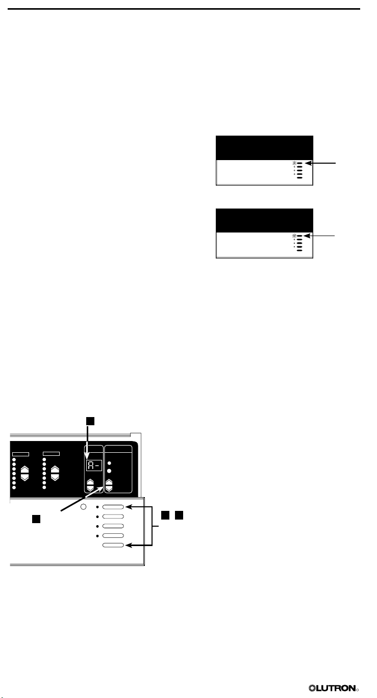
Assigning an Address to Each Control Unit
If your lighting system has multiple control units, assign a unique system address (A1 through
A8) to each control unit. Once any control unit has been addressed, communication is lost
between all other components until each control unit has been addressed. To program a
wallstation, refer to its documentation.
NOTE: A single control unit operating shade zones must also be addressed.
To address each control unit:
1. Enter setup mode. Press and hold the
SCENE 1 and OFF buttons for about
three seconds, until the scene LEDs
cycle.
2. Select A-. Press the FADE button
until A- (the factory default address)
displays in the FADE window.
3. Assign a unique address. Press the
MASTER button once; the next “free”
(unassigned) address automatically
displays in the FADE window. This will
be the control unit’s address. (If you are
working on the first control unit in the
lighting system, A1 will display.)
4. Exit setup mode. Press and hold the
SCENE 1 and OFF buttons for about
three seconds, until the LEDs stop
cycling.
5. Repeat steps 1 through 4 for each
control unit.
Assign a
unique address
Select A-
Enter (exit)
setup mode
20 GRAFIK Eye® 3000 Series Control Unit Installer’s Guide
R
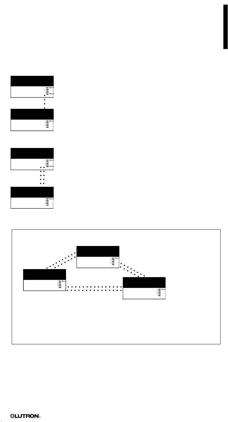
Setting Up Communications between Two or More Control Units
Two-way communications between control units enables you to set up lighting and shade effects
for more than six zones (the maximum number of zones any one control unit can operate).
Depending on the room or facility, you can set up two-way communications so that all control
units “talk” and “listen” to each other. In this configuration, selecting a scene at any one of the
control units automatically activates the same scene in the others. Optionally, you set up some
control units to share two-way communications while others do not. This configuration enables
you to specify which control units activate the same scenes and which work independently.
NOTE: The control units must be addressed (as described on page 20) before setting up twoway communications.
A1 “talks” . . .
LEDs cycle
. . . A2 “listens”
LEDs flash
A1 “listens” . . .
LEDs cycle
. . . when A2 “talks”
LEDs flash
Example: Three Control Units All Communicating for 16-Zone Control
To set up communications between control units:
1. Put A1 in setup mode. Press and hold the SCENE 1 and OFF
buttons for about three seconds, until the LEDs cycle.
2. Identify the control units that should “listen” to A1 (A2 and
up to six others). At each of the other control units, press and
hold the SCENE 1 button for about three seconds until the LEDs
flash in unison, showing that these control unit(s) are “listening” to
A1 and will respond to its commands.
To make a “listening” control unit not listen to A1: Put A1 in
setup mode, then press the “listening” control unit’s OFF button
until the LEDs stop flashing.
3. Take A1 out of setup mode. Press and hold the SCENE 1 and
OFF buttons for about three seconds, until the LEDs on A1 and
all other linked control units stop cycling.
You have set up communications in one direction between A1
and all “listening” control units.
4. To complete the two-way communication, reverse the
process described above. Put A2 in setup mode; then make
A1 (and any other control units) “listen”; then take A2 out of
setup mode. Continue for each control unit.
A1
6 zo
nes
Selecting a
scene on
A1 . . .
A2
6 zones
A3
4 zones
All three control units are programmed to communicate with one another and act like a 16zone control unit. Note that communications are set up both ways among all control units:
• A1 “talks” and “listens” to A2 and A3.
• A2 “talks” and “listens” to A1 and A3.
• A3 “talks” and “listens” to A1 and A2.
Setting Up Communications between Control Units, Wallstations, and Other Accessories
Wallstations and other optional accessories (refer to page 3) must be set up to communicate
with control units on the GRAFIK Eye link. For procedures on how to set up communications
with wallstations and accessories, refer to the separate instructions included with the device.
GRAFIK Eye® 3000 Series Control Unit Installer’s Guide 21
. . . Activates the
same scene on A2
and A3.

R
Appendix A
Troubleshooting
Problem Possible Cause Remedy
Unit does not turn lights on
Long fade time Set FADE time to 0 seconds.
Low zone settings Use ZONE
Miswire Check wirin
on page 5)
System short circuit Find and correct shorts in fixtures
and/or wallbox.
System
Wrong load type Check load type setting.
Breaker/MCB is off Switch breaker/MCB on.
5 button for each scene.
g (refer to wiring details
.
overload Make sure lighting loads don’t exceed unit’s
maximum rated load.
Unit does not control load
or ZONE control does not work
Disconnected wires Connect zone wires to loads (refer to page 5).
Burned-out lamps Replace bad lamps.
1 or more zones are “full-on”
when any scene is on and
zone intensity is not a
(and zone is
Shorted triac Replace control unit.
A ZONE control affects
more than one zone Miswire
Wallstation does not
function properly
Incorrect programming Check wallstation programming.
Faceplate is warm Normal operation Solid-state controls dissipate about 2% of the
Unit does not allow scene
changes or zone
adjustments Wrong
Unit does not allow shade
changes or a
not a non-dim)
djustments Incorrect programming Check programming. Control unit must be correctly
Miswire Check wiring (refer to wiring details on page 5).
djustable
Miswire Make sure loads are connected to the right zones
Check wiring (refer to wiring details on page 5).
Miswire or loose connection
save mode Refer to page 17 for a description of save modes.
(refer to wiring details on page 5).
Tighten loose connections at PELV (Class 2: USA)
terminals on unit and wallstations (refer to page 6).
connected load as heat. For spacing and ventilation
considerations, refer to pages 9 and 10.
addressed; see page 20.
NOTE: Contact Lutron Technical Support for additional troubleshooting assistance.
22 GRAFIK Eye® 3000 Series Control Unit Installer’s Guide

Warranty
R
Lutron Electronics Co., Inc.
One Year Limited Warranty
For a period of one year from the date of purchase, and subject to the exclusions and restrictions described below,
Lutron warrants each new unit to be free from manufacturing defects. Lutron will, at its option, either repair the
defective unit or issue a credit equal to the purchase price of the defective unit to the Customer against the purchase
price of comparable replacement part purchased from Lutron. Replacements for the unit provided by Lutron or,
at its sole discretion, an approved vendor may be new, used, repaired, reconditioned, and/or made by a different
manufacturer.
If the unit is commissioned by Lutron or a Lutron approved third party as part of a Lutron commissioned lighting
control system, the term of this warranty will be extended, and any credits against the cost of replacement parts will
be prorated, in accordance with the warranty issued with the commissioned system, except that the term of the unit’s
warranty term will be measured from the date of its commissioning.
EXCLUSIONS AND RESTRICTIONS
This Warranty does
1. Damage, malfunction or inoperability diagnosed by Lutron or a Lutron approved third party as caused by normal
wear and tear, abuse, misuse, incorrect installation, neglect, accident, interference or environmental factors, such
as (a) use of incorrect line voltages, fuses or circuit breakers; (b) failure to install, maintain and operate the unit
pursuant to the operating instructions provided by Lutron and the applicable provisions of the National Electrical
Code and of the Safety Standards of Underwriter’s Laboratories; (c) use of incompatible devices or accessories; (d)
improper or insufficient ventilation; (e) unauthorized repairs or adjustments; (f) vandalism; or (g) an act of God, such
as fire, lightning, flooding, tornado, earthquake, hurricane or other problems beyond Lutron’s control.
2. On-site labor costs to diagnose issues with, and to remove, repair, replace, adjust, reinstall and/or reprogram the
unit or any of its components.
3. Equipment and parts external to the unit, including those sold or supplied by Lutron (which may be covered by a
separate warranty).
4. The cost of repairing or replacing other property that is damaged when the unit does not work properly, even if the
damage was caused by the unit.
EXCEPT AS EXPRESSLY PROVIDED IN THIS WARRANTY, THERE ARE NO EXPRESS OR IMPLIED
WARRANTIES OF ANY TYPE, INCLUDING ANY IMPLIED WARRANTIES OF FITNESS FOR A PARTICULAR
PURPOSE OR MERCHANTABILITY. LUTRON DOES NOT WARRANT THAT THE UNIT WILL OPERATE WITHOUT
INTERRUPTION OR BE ERROR FREE.
NO LUTRON AGENT, EMPLOYEE OR REPRESENTATIVE HAS ANY AUTHORITY TO BIND LUTRON TO ANY
AFFIRMATION, REPRESENTATION OR WARRANTY CONCERNING THE UNIT. UNLESS AN AFFIRMATION,
REPRESENTATION OR WARRANTY MADE BY AN AGENT, EMPLOYEE OR REPRESENTATIVE IS SPECIFICALLY
INCLUDED HEREIN, OR IN STANDARD PRINTED MATERIALS PROVIDED BY LUTRON, IT DOES NOT FORM A
PART OF THE BASIS OF ANY BARGAIN BETWEEN LUTRON AND CUSTOMER AND WILL NOT IN ANY WAY BE
ENFORCEABLE BY CUSTOMER.
IN NO EVENT WILL LUTRON OR ANY OTHER PARTY BE LIABLE FOR EXEMPLARY, CONSEQUENTIAL,
INCIDENTAL OR SPECIAL DAMAGES (INCLUDING, BUT NOT LIMITED TO, DAMAGES FOR LOSS OF PROFITS,
CONFIDENTIAL OR OTHER INFORMATION, OR PRIVACY;
FAILURE TO MEET
ANY OTHER PECUNIARY OR OTHER LOSS WHATSOEVER), NOR FOR ANY REPAIR WORK UNDERTAKEN
WITHOUT LUTRON’S WRITTEN CONSENT ARISING OUT OF OR IN ANY WAY RELATED TO THE INSTALLATION,
DEINSTALLATION, USE OF OR INABILITY TO USE THE UNIT OR OTHERWISE UNDER OR IN CONNECTION WITH
ANY PROVISION OF THIS WARRANTY, OR ANY AGREEMENT INCORPORATING THIS WARRANTY, EVEN IN
THE EVENT OF THE FAULT, TORT (INCLUDING NEGLIGENCE), STRICT LIABILITY, BREACH OF CONTRACT OR
BREACH OF WARRANTY OF LUTRON OR ANY SUPPLIER, AND EVEN IF LUTRON OR ANY OTHER PARTY WAS
ADVISED OF THE POSSIBILITY OF SUCH DAMAGES.
NOTWITHSTANDING ANY DAMAGES THAT CUSTOMER MIGHT INCUR FOR ANY REASON WHATSOEVER
(INCLUDING, WITHOUT LIMITATION, ALL DIRECT DAMAGES AND ALL DAMAGES LISTED ABOVE), THE ENTIRE
LIABILITY OF LUTRON AND OF ALL OTHER PARTIES UNDER THIS WARRANTY ON ANY CLAIM FOR DAMAGES
ARISING OUT OF OR IN CONNECTION WITH THE MANUFACTURE, SALE, INSTALLATION, DELIVERY, USE,
REPAIR, OR REPLACEMENT OF THE UNIT, OR ANY AGREEMENT INCORPORATING THIS WARRANTY, AND
CUSTOMER’S SOLE REMEDY FOR THE FOREGOING, WILL BE LIMITED TO THE AMOUNT PAID TO LUTRON
BY CUSTOMER FOR THE UNIT. THE FOREGOING LIMITATIONS, EXCLUSIONS AND DISCLAIMERS
TO THE MAXIMUM EXTENT ALLOWED
PURPOSE.
TO MAKE A WARRANTY CLAIM
To make a warranty claim, promptly notify Lutron within the warranty period described above by calling the Lutron
Technical Support Center at (800) 523-9466. Lutron, in its sole discretion, will determine what action, if any, is
required under this warranty. To better enable Lutron to address a warranty claim, have the unit’s serial and model
numbers available when making the call. If Lutron, in its sole discretion, determines that an on-site visit or other
remedial action is necessary, Lutron may send a Lutron Services Co. representative or coordinate the dispatch of a
representative from a Lutron approved vendor to Customer’s site, and/or coordinate a warranty service call between
Customer and a Lutron approved vendor.
This warranty gives you specific legal rights, and you may also have other rights which vary from state to state.
Some states do not allow limitations on how long an implied warranty lasts, so the above limitation may not apply
to you. Some
limitation or exclusion may not
National Electrical Code (NEC) is a registered trademark of the National Fire Protection Association, Inc., Quincy,
Massachusetts.
Lutron, the sunburst logo, Hi-Lume, Tu-Wire, Sivoia, Eco-10 and GRAFIK Eye are registered trademarks, and
•4•6 is a trademark of Lutron Electronics Co., Inc.
HP 2
© 2011 Lutron Electronics Co., Inc.
not cover, and Lutron and its suppliers are not responsible for:
ANY DUTY, INCLUDING OF GOOD FAITH OR OF REASONABLE CARE; NEGLIGENCE, OR
BY APPLICABLE LAW, EVEN IF ANY REMEDY FAILS ITS ESSENTIAL
states do not allow the exclusion or limitation of incidental or consequential damages, so the above
apply to you.
BUSINESS INTERRUPTION; PERSONAL INJURY;
WILL APPLY
GRAFIK Eye® 3000 Series Control Unit Installer’s Guide 23

R
Contact Information
Internet: www.lutron.com
E-mail: product@lutron.com
WORLD HEADQUARTERS
USA
Lutron Electronics Co., Inc.
7200 Suter Road, Coopersburg, PA 18036-1299
TEL +1.610.282.3800
FAX +1.610.282.1243
Toll-Free 1.888.LUTRON1
Technical Support 1.800.523.9466
Brazil
Lutron BZ do Brasil Ltda.
AV, Brasil, 239, Jardim America
Sao Paulo-SP, CEP: 01431-000, Brazil
TEL +55.11.3885.5152
FAX +55.11.3887.7138
North and South America Technical Hotlines
USA, Canada, Caribbean: 1.800.523.9466
Mexico: +1.888.235.2910
Central/South America: +1.610.282.6701
EUROPEAN HEADQUARTERS
United Kingdom
Lutron EA Ltd.
6 Sovereign Close, London, E1W 3JF United Kingdom
TEL +44.(0)20.7702.0657
FAX +44.(0)20.7480.6899
FREEPHONE (UK) 0800.282.107
Technical support +44.(0)20.7680.4481
WORLDWIDE OFFICES
France
Lutron LTC, S.A.R.L.
90 rue de Villiers, 92300 Levallois-Perret France
TEL +33.(0)1.41.05.42.80
FAX +33.(0)1.41.05.01.80
FREEPHONE 0800.90.12.18
Germany
Lutron Electronics GmbH, Landsberger Allee 201,
13055 Berlin, Germany
TEL +49.(0)30.9710.4590
FAX +49.(0)30.9710.4591
FREEPHONE 00800.5887.6635
Italy
Lutron LDV, S.r.l.
FREEPHONE 800.979.208
Spain, Barcelona
Lutron CC, S.R.L.
Gran Via del Carlos III, 84, planta 3
08028, Barcelona, Spain
TEL +34.93.496.57.42
FAX +34.93.496.57.01
FREEPHONE 0900.948.944
Spain, Madrid
Lutron CC, S.R.L.
Calle Orense, 85, 28020 Madrid, Spain
TEL +34.91.567.84.79
FAX +34.91.567.84.78
FREEPHONE 0900.948.944
a
,
ASIAN HEADQUARTERS
Singapore
Lutron GL Ltd.
15 Hoe Chiang Road, #07-03 Euro Asia Centre,
Singapore 089316
TEL +65.6220.4666
FAX +65.6220.4333
China, Beijing
Lutron GL Ltd. Beijing Representative Office
5th Floor, China Life Tower
No. 16 Chaowai Street, Chaoyang District, Beijing
100020 China
TEL +86.10.5877.1817
FAX +86.10.5877.1816
China, Shanghai
Lutron GL Ltd., Shanghai Representative Office
Suite 07, 39th Floor, Plaza 66
1266 Nan Jing West Road, Shanghai, 200040 China
TEL +86.21.6288.1473
FAX +86.21.6288.1751
China, Hong Kong
Lutron GL Ltd.
Unit 2808, 28/F, 248 Queen’s Road East
Wanchai, Hong Kong
TEL +852.2104.7733
FAX +852.2104.7633
Japan
Lutron Asuka Co. Ltd.
No. 16 Kowa Building, 4F, 1-9-20
Akasaka, Minato-ku, Tokyo 107-0052 Japan
TEL +81.3.5575.8411
FAX +81.3.5575.8420
FREEPHONE 0120.083.417
Asia Technical Hotlines
Northern China: 10.800.712.1536
Southern China: 10.800.120.1536
Hong Kong: 800.901.849
Japan: +81.3.5575.8411
Singapore: 800.120.4491
Taiwan: 00.801.137.737
Thailand: 001.800.120.665853
Other countries: +800.120.4491
Lutron Electronics Co., Inc.
P/N 032-379 Rev. A 5/2011
LUTRON
®
Serie 3000 Guía
R
del instalador
Unidades de Control Modelos 3100 y 3500
POR FAVOR LEA
Sección 1: Introducción
Unidad de Control GRAFIK Eye® Serie 3000 . . . . . . . . . . . . . . . . . . . . . . . . . . . . . . . . . . . . . . 2
Comunicaciones del Sistema y Capacidades . . . . . . . . . . . . . . . . . . . . . . . . . . . . . . . . . . . . . 3
Sección 2: Instalación de una Unidad de Control GRAFIK Eye®
Paso 1: verifique las Caras para que no haya cortocircuitos . . . . . . . . . . . . . . . . . . . . . . . . . . 4
Paso 2: DESCONECTE la alimentación . . . . . . . . . . . . . . . . . . . . . . . . . . . . . . . . . . . . . . . . . . 4
Paso 3: Monte la Caja de pared . . . . . . . . . . . . . . . . . . . . . . . . . . . . . . . . . . . . . . . . . . . . . . . 5
Paso 4: Conecte los cables de línea/alimentación a la Unidad de Control. . . . . . . . . . . . . . . . 5
Paso 5: Conecte Cable PELV (Clase 2: EE.UU.) a la Unidad de control – Opcional. . . . . . . . . 6
Paso 6: Monte la Unidad de control . . . . . . . . . . . . . . . . . . . . . . . . . . . . . . . . . . . . . . . . . . . . 7
Paso 7: Pruebe la Unidad de control. . . . . . . . . . . . . . . . . . . . . . . . . . . . . . . . . . . . . . . . . . . . 7
Paso 8: Conecte las Estaciones – Opcionales. . . . . . . . . . . . . . . . . . . . . . . . . . . . . . . . . . . . . 8
Paso 9: Conecte Otros Accesorios – Opcional . . . . . . . . . . . . . . . . . . . . . . . . . . . . . . . . . . . . 8
Paso 10: Conecte Múltiples Unidades de control – Opcional . . . . . . . . . . . . . . . . . . . . . . . . . 9
Consideraciones de Montajes Especiales . . . . . . . . . . . . . . . . . . . . . . . . . . . . . . . . . . . . . . . . 9
Instalación de una fuente de alimentación externa. . . . . . . . . . . . . . . . . . . . . . . . . . . . . . . . . . 10
Sección 3: Programación de una unidad de Control GRAFIK Eye®.
Botones e indicadores de la unidad de control . . . . . . . . . . . . . . . . . . . . . . . . . . . . . . . . . . . . 11
Entrar y Salir del Modo Configuración . . . . . . . . . . . . . . . . . . . . . . . . . . . . . . . . . . . . . . . . . . . 11
Identificación del tipo de carga de cada zona . . . . . . . . . . . . . . . . . . . . . . . . . . . . . . . . . . . . . 12
Programación de las Escenas . . . . . . . . . . . . . . . . . . . . . . . . . . . . . . . . . . . . . . . . . . . . . . . . . 14
Ajuste del extremo alto o bajo . . . . . . . . . . . . . . . . . . . . . . . . . . . . . . . . . . . . . . . . . . . . . . . . . 17
Selección del Modo Guardar que quiere usar . . . . . . . . . . . . . . . . . . . . . . . . . . . . . . . . . . . . . 17
Sección 4: Uso de la Unidad de Control GRAFIK Eye®
Selección de escenas . . . . . . . . . . . . . . . . . . . . . . . . . . . . . . . . . . . . . . . . . . . . . . . . . . . . . . . 18
Ajuste Temporal de los Niveles de luz y las Posiciones de las Cortinas. . . . . . . . . . . . . . . . . . 18
Configuración de las Comunicaciones. . . . . . . . . . . . . . . . . . . . . . . . . . . . . . . . . . . . . . . . . . . 20
Apéndice A: Solución de Problemas . . . . . . . . . . . . . . . . . . . . . . . . . . . . . . . . . . . . . . . . . . . 22
Garantía . . . . . . . . . . . . . . . . . . . . . . . . . . . . . . . . . . . . . . . . . . . . . . . . . . . . . . . . . . . . . . . . . 23
Información de contacto . . . . . . . . . . . . . . . . . . . . . . . . . . . . . . . . . . . . . . . . . . . . . . . . . . . . . 24
Español
Esta guía para el instalador explica cómo instalar y programar una unidad de control GRAFIK Eye
Serie 3000. Use esta guía en conjunto con las instrucciones de instalación suministradas por
separado con los otros productos GRAFIK
Eye Serie 3000.
Sistemas de Calidad LUTRON-
Registrados según ISO 9001

R
Secci
M S
FADE TEMPORARY
MASTER
ZONES
ZONE 5 ZONE 6ZONE 3 ZONE 4ZONE 1 ZONE 2
ó
n 1:
Introducción
Esta sección de la guía de instalación introduce el sistema de iluminación y la unidad de control
GRAFIK Eye Serie 3000. También describe las comunicaciones y capacidades del sistema. Lea
cuidadosamente esta Introducción antes de proceder con las instrucciones de instalación que
comienzan en la página 4.
Unidad de Control GRAFIK Eye® Serie 3000
El GRAFIK Eye es parte de un sistema de control de iluminación que le permite crear escenas
personalizadas y controlar la iluminación y zonas de cortinas.
La unidad de control es la pieza central del sistema de control
de iluminación. La unidad de control provee:
• Configuración de las escenas de iluminación y control de
cortinas usando lo botones de la unidad de control.
• Ejecución de cuatro escenas de iluminación programadas más
APAGADO con sólo apretar un botón.
• 12 escenas adicionales almacenadas en la unidad de control,
accesibles vía estaciones de control de pared opcionales y otros dispositivos de control.
• Control de 2, 3, 4, o 6 zonas.
• Suave desvanecimiento del nivele de iluminación entre escenas.
• Opciones de bloqueo para impedir cambios accidentales.
• Receptor infrarrojo incorporado para la utilización de un control remoto opcional.
Todo esto puede ser ejecutado en una única unidad de control. Pueden conectarse hasta
8 unidades de control con
agrandar el sistema y agregar funciones adicionales de control.
Las funciones adicionales disponibles con el modelo 3500 se acceden a través del control por
modelo e incluyen:
• Incrementos en el nivel de iluminación de 1%
• Control virtual a través del software Liaison
• Control de cortinas a través de una interfaz RS232
Números de Modelo y Valores nominales
Número de Modelo Voltaje
50 / 60 Hz
2 Zonas
GRX-3102, GRX-3502 120 V~ 1 200 W/VA 25 - 800 W
GRX-3102-CE, GRX-3502-CE 230 V~ 1 600 W/VA 40 - 800 W
GRX-3102-AU, GRX-3502-AU 220 - 240 V~ 1 600 W/VA 40 - 1 200 W
GRX-3102-JA, GRX-3502-JA 100 V~ 1 050 W/VA 25 - 600 W
3 Zonas
GRX-3103, GRX-3503 120 V~ 1 500 W/VA 25 - 800 W
GRX-3103-CE, GRX-3503-CE 230 V~ 2 300 W/VA 40 - 800 W
GRX-3103-AU, GRX-3503-AU 220 - 240 V~ 2 400 W/VA 40 - 1 200 W
GRX-3103-JA, GRX-3503-JA 100 V~ 1 250 W/VA 25 - 600 W
4 Zonas
GRX-3104, GRX-3504 120 V~ 2 000 W/VA 25 - 800 W
GRX-3104-CE, GRX-3504-CE 230 V~ 2 300 W/VA 40 - 800 W
GRX-3104-AU, GRX-3504-AU 220 - 240 V~ 3 000 W/VA 40 - 1 200 W
GRX-3104-JA, GRX-3504-JA 100 V~ 1 600 W/VA 25 - 600 W
6 Zonas
GRX-3106, GRX-3506 120 V~ 2 000 W/VA 25 - 800 W
GRX-3106-CE, GRX-3506-CE 230 V~ 2 300 W/VA 40 - 800 W
GRX-3106-AU, GRX-3506-AU 220 - 240 V~ 3 000 W/VA 40 - 1 200 W
GRX-3106-JA, GRX-3506-JA 100 V~ 1 600 W/VA 25 - 600 W
estaciones de pared, sensores, y otras interfaces de control para
TM
Valores Nominales
Máximos
Unitarios Rangos de Zonas
Fuentes/Tipos de Carga
Las Unidades de Control pueden controlar tipos de carga incandescente, halógena (tungsteno),
bajo voltaje magnético y neón/cátodo frío. Los tipos de carga electrónicas de bajo voltaje y
fluorescente, y las cortinas, se pueden controlar con las interfaces apropiadas.
2 Guía de Instalación de la Unidad de Control GRAFIK Eye® Serie 3000

R
Programación de Fábrica
Lutron entrega cada unidad de control con los siguientes valores programados en fábrica
(modo A-). En este modo, las unidades de control las estaciones de control de iluminación se
comunican sin programación adicional.
Parámetro Programación de Fábrica
Dirección Sin dirección (configurado por defecto en fábrica en A-)
Tipo de carga Todas las zonas configuradas como incandescentes
Escena 1 100% de intensidad para todas las zonas
Escena 2 75% de intensidad para todas las zonas
Escena 3 50% de intensidad para todas las zonas
Escena 4 25% de intensidad para todas las zonas
Escenas 5 - 16 100% de intensidad para todas las zonas
APAGADO (escena 0) Todas las zonas APAGADAS
Tiempos de desvanecimiento 3 segundos entre todas las escenas; 10-segundos de
desvanecimiento hasta APAGAR
Tiempo de variación gradual 4 segundos hasta cualquier escena (no ajustable)
desde APAGADO
Modo guardar Sd (guardado por defecto)
Nota: El tiempo de desvanecimiento afecta a las luces pero no a las cortinas; éstas se mueven
inmediatamente a su nivel programado.
Accesorios
Dependiendo del tamaño y requerimientos del sistema de iluminación, las unidades de control
pueden ser configuradas para trabajar con una variedad de accesorios opcionales, incluyendo:
• Estaciones de control de bajo voltaje. Estaciones de control, controladores de cortinas,
sensores y receptores infrarrojos (IR), y controles de quicio de la puerta.
• Interfaces de Control. Dispositivos de cierre de contacto seco, comunicaciones digitales por
RS232 y Ethernet. reloj temporizador astronómico, e interfaz de programación para el software
GRAFIK Eye LiaisonTM.
• Interfaces de Carga. Se requieren para todas las cargas que excedan la capacidad máxima
de la zona (ver la página 2), así como para los balastos fluorescentes de 3 vías de Lutron, la
iluminación electrónica de bajo voltaje, y las cargas de 277 V .
Por números de pieza e información adicional sobre los accesorios para GRAFIK Eye Serie
3000, visite www.lutron.com.
Comunicaciones del Sistema y Capacidades
Puede usarse cable PELV (Clase 2: EE.UU.) para conectar las unidades de control, estaciones
de control, y otros accesorios GRAFIK Eye Serie 3000. Se pueden vincular hasta 8 unidades
de control para controlar hasta 48 zonas, y agregar 16 estaciones de control y 8 controladores
de cortinas (SG-SVC) para un total de 32 puntos de control. Note que las estaciones
de control controlan escenas (que pueden incluir parámetros de luz y de cortinas); los
controladores de cortinas solamente controlan cortinas.
Cables PELV (Clase 2: EEUU).
Si su sistema de iluminación usa estaciones de control y/o múltiples unidades de
control, se necesita cableado PELV (Clase 2: EE.UU.) para suministrar alimentación y
comunicaciones entre las unidades y las estaciones de control. Se necesita también cableado
PELV (Clase 2: EE.UU.) para conectar otros accesorios.
Use cable correctamente certificado como PELV (Clase 2: EE.UU.). Cada par trenzado en el vínculo de
cableado PELV (Clase 2: EE.UU.) debe consistir de dos conductores 1,0 mm2 trenzados.
• Un par es para el cableado de alimentación de bajo voltaje.
• El segundo par es para el enlace de datos (hasta 610 m de largo).
Nota: Lutron ofrece una solución de un cable, de bajo voltaje: P/N GRX-CBL-346S (sin pleno) o GRX-
PCBL-346S (plenum). Verifique la disponibilidad y los códigos eléctricos aplicables en su área.
En los países que siguen las regulaciones de la IEC, es común hacer referencia a PELV
como Voltaje Extra Bajo de Protección. Un circuito PELV es un circuito con conexión a tierra
en el cual el voltaje no puede exceder los 50 V o 120 V libres de distorsión. La fuente de
alimentación debe ser provista por un transformador de aislamiento de seguridad o equivalente.
Los cables sin blindaje recomendados incluyen:
• Para estaciones sin pleno, utilice (2) Belden 9470, (1) Belden 9156 o (2) Liberty 181P/2C-EX-
GRN o equivalentes.
• Para estaciones con pleno, utilice (2) Belden 82740 o equivalente.
En Europa, entre los tipos de cable aceptable se encuentra el cable certificado por HAR con centros
envainados. Este cable deberá llevar la marca de certificación correspondiente a las reglas nacionales
de cableado de instalaciones fijas. Si se utiliza cable con centros envainados certificado para la
Alimentación, el cableado PELV podrá realizarse con cualquiera de los cables especificados más arriba.
Guía de Instalación de la Unidad de Control GRAFIK Eye® Serie 3000 3
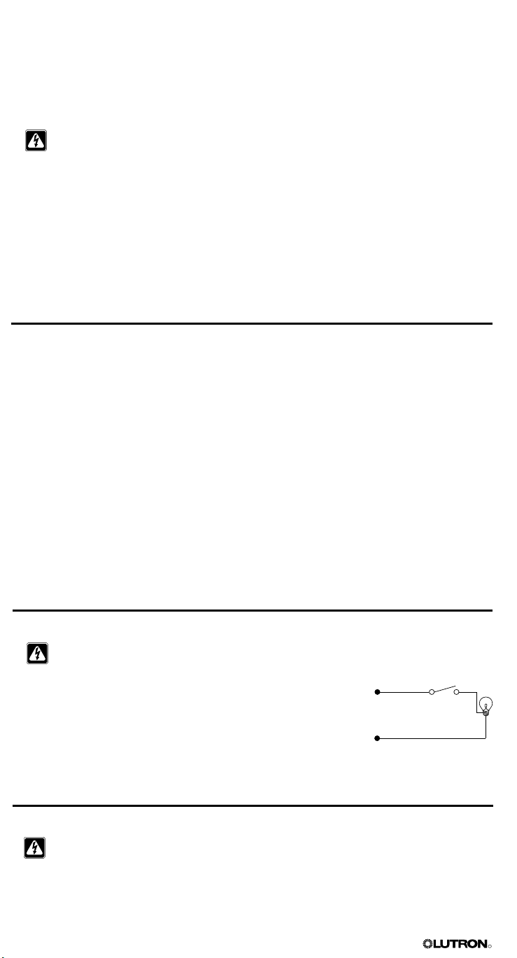
R
Secci
ó
n 2:
Instalación de una Unidad de Control
GRAFIK Eye®
Esta sección explica cómo instalar una unidad de control GRAFIK Eye y cómo asegurarse de
que todas las cargas conectadas estén operando correctamente.
¡PELIGRO! Las unidades de control GRAFIK Eye Serie 3000 deben ser instaladas por un
electricista calificado de acuerdo con todas las regulaciones y códigos de construcción
aplicables. El cableado incorrecto puede resultar en daños personales o de las unidades
de control u otros equipos. Siempre desconecte el interruptor de circuitos o quite el fusible
de alimentación de línea antes de efectuar cualquier trabajo. Para evitar el calentamiento y
posible daóo del equipo, no instale dispositivos de atenuación para atenuar receptáculos,
artefactos operados por motores, o iluminación fluorescente que no esté equipada
con balastos de atenuación electrónica Lutron Hi-lume®, Eco-10TM, o Tu-Wire®, o con
dispositivos aprobados para su ubicación. En circuitos atenuados magnéticos de bajo voltaje,
se puede prevenir el calentamiento del transformador y las fallas evitando el flujo excesivo
de corriente: No opere las unidades de control con lámparas removidas o quemadas;
reemplace inmediatamente todas las lámparas quemadas; use solamente transformadores
que incorporen protección térmica o bobinados primarios con fusible. Las unidades de control
están diseñadas para el uso residencial y comercial, y solamente para interiores.
Información Importante Sobre Cargas y Cajas de Empotrar
Las Unidades de control GRAFIK Eye Serie 3000 pueden controlar cargas del tipo
incandescente, halógena (tungsteno), magnéticas de bajo voltaje, y de neón/cátodo frío.
Muchas cargas atenuables fluorescentes, electrónicas de bajo voltaje, y de cortinas pueden ser
controladas con las interfaces adecuadas.
• Toda la iluminación electrónica de bajo voltaje (ELV) utilizada con la interfaz electrónica de bajo
voltaje debe ser adecuada para la atenuación por control de inversión de fase, también
conocida como atenuación de extremos posterior. Antes de instalar una fuente de luz
ELV, consulte con el fabricante si su transformador puede ser atenuado. Cuando se realice
la atenuación, SE REQUIERE la utilización de una interfaz electrónica de bajo voltaje con la
unidad de control.
• Contacte a Lutron o consulte los diagramas de su trabajo para información sobre otros
productos de interfaz.
• No todas las zonas de la unidad de control necesitan ser conectadas; sin embargo, las zonas
conectadas deben tener una carga de al menos 25 W (40 W para los modelos AU y CE).
• Ninguna zona puede tener una carga mayor que 800 W (1 200 W para los modelos AU).
• Vea la página 2 por los valores unitarios máximos.
Paso 1: Asegúrese de que no haya cortocircuitos en la carga.
¡PRECAUCIÓN! Antes de conectar las cargas a la unidad de control, verifique que no
haya cortocircuitos.
1. DESCONECTE la alimentación en el interruptor o en la caja de fusibles.
2. Conecte un interruptor estándar de luz entre el conductor vivo y el
cable de la carga para probar el circuito.
3. Alimente el circuito y asegúrese que no haya cortocircuitos o circuitos
abiertos: Si la carga no funciona, es que el circuito está abierto. Si
el interruptor/MCB se dispara (el fusible se quema o abre), puede haber un cortocircuito en la
carga. Corrija los cortocircuitos o circuitos abiertos y vuelva a realizar la prueba.
Vivo
Neutro
Interruptor
Paso 2: CONECTE la alimentación
¡PRECAUCIÓN! Antes de continuar con la instalación, verifique que la alimentación está
DESCONECTADA en el interruptor o en la caja de fusibles. No realice el cableado con la
alimentación CONECTADA.
4 Guía de Instalación de la Unidad de Control GRAFIK Eye® Serie 3000
Carga
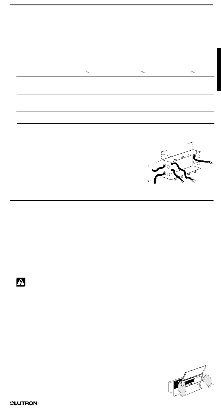
R
Paso 3: Monte la Caja de pared
230V
˜
LUTRON
5
0/6
0H
z
LO
AD
P
E
R
ZONE: 40 - 80
0
W
M
AX
UNIT LO
A
D: 1
0
A, 2300W
P
rese
t
Ligh
ting C
o
ntro
l
LIVE TERMINALS
AT
RE
AR
DO NOT WIRE LIVE
U.
K. 0
71
-70
2
-0657
U
.
S.
A
. (610) 282
-3
800
CO
O
PERS
B
UR
G
,
PA U
SA 18
0
36
GR
X-3104-
CE
UP
Ma
d
e in U
.S.A.
1
2V
S
E
LV
O
UTPU
T
!
CB
E
5
145-0
49
G
R
X
-Z
1. Monte una caja de empotrar estándar EE.UU. en una superficie seca y plana, interior, que sea
accesible y permita la programación y operación del sistema. Vea la tabla más abajo para la
caja de empotrar recomendada para cada modelo.
Use una profundidad mínima de 68 mm, preferentemente 87 mm. Deje por lo menos 110 mm
de espacio libre por arriba y por debajo de la placa frontal para asegurar una correcta
disipación de calor. Deje 25 mm de espacio en todos los lados de la placa frontal.
NOTA: para el montaje
en un panel, consulte la página 10.
Modelo de la
Unidad de control 100 - 120 V
GRX-3102/3502
GRX-3103/3503
GRX-3104/3504
GRX-3106/3506
Caja de empotrar de 2 posiciones
o dos cajas de empotrar de una
posición
Caja de empotrar de 3 posiciones
o tres cajas de empotrar de una
posición
Caja de empotrar de 4 posiciones
Caja de empotrar de 4 posiciones
NOTA: Caja de empotrar de una posición P/N 241218;
Caja de empotrar de 4 posiciones P/N 241400.
2. Pase los cables de voltaje de línea de alimentación dentro
la caja de empotrar usando los orificios de más atrás. Esto
230 V (CE) 220 - 240 V (AU)
Caja de empotrar
de 4 posiciones
Caja de empotrar
de 4 posiciones
Caja de empotrar
de 4 posiciones
Caja de empotrar
de 4 posiciones
87 mm
Caja de empotrar de 2
posiciones o dos cajas de
empotrar de una posici
Caja de empotrar de 3
posiciones o tres cajas de
empotrar de una posici
Caja de empotrar de 4
posiciones
Caja de empotrar de 4
posiciones
200 mm
ó
ó
brindará la mayor abertura al montar la unidad de control.
Si la unidad de control va a ser conectada a estaciones y/o
unidades de control adicionales, pase también los cables
95 mm
PELV (Clase 2: EE.UU.) dentro de la caja de empotrar
usando los orificios posteriores restantes (consulte la
página 7). Use el cable recomendado especificado en “Cables PELV (Clase 2: EE.UU.)” en la página 3.
Paso 4: Conecte los Cables del Voltaje de línea/Alimentación
en la Unidad de control
Información Importante sobre Cableado
• Utilice cable que esté apropiadamente certificado para todos los cables de las líneas de voltaje/
alimentación.
• Se debe brindar protección apropiada contra cortocircuitos y sobrecargas en el panel de
distribución. Podrá usar interruptores/corta circuitos de hasta un máximo de 20 A (16 A para
AU y 10 A para los modelos CE) o equivalentes (es recomendable una curva de disparo C
según IEC60898/EN60898) con una capacidad de interrupción de cortocircuitos adecuada
para su instalación.
• Realice la instalación de acuerdo con todos los códigos eléctricos locales y nacionales.
¡Cuidado! No conecte cable de línea de voltaje/alimentación a los bornes (Clase 2: PELV).
n
n
• La conexión del borne de tierra/masa debe realizarse como se muestra en los diagramas de
cableado de la página 6.
• ¡No mezcle distintos tipos de carga en la misma zona!
• Consulte la página 3 por dispositivos que requieren interfaces. Cablee como se especifica en la
documentación de la interfaz.
• Los cables de la línea de voltaje/alimentación deben tener una separación de los cables PELV
(Clase 2: EE.UU.) y del bloque de terminales de al menos 7 mm.
Para conectar los cables de línea/alimentación a la unidad de control:
1. Quite la tapa de la unidad de control y la placa frontal tirando hacia afuera de cada una de las
esquinas.
2. Pele 12 mm de aislación de los cables de línea/alimentación en la caja de empotrar.
3. Conecte los cables de voltaje de línea, tierra y carga a los bornes correspondientes en la parte
posterior de la unidad de control, como se muestra en la página 6 para
los modelos GRX, GRX-AU y GRX-CE.
El torque recomendado para la instalación es de 1,0 N•m para las
conexiones de voltaje de línea y 1,3 N•m para la conexión de tierra/masa.
Cada borne de alimentación puede aceptar hasta dos cables 2,5 mm2.
Esto no corresponde al bloque de bornes PELV (Clase 2: EE.UU.)
Guía de Instalación de la Unidad de Control GRAFIK Eye® Serie 3000 5
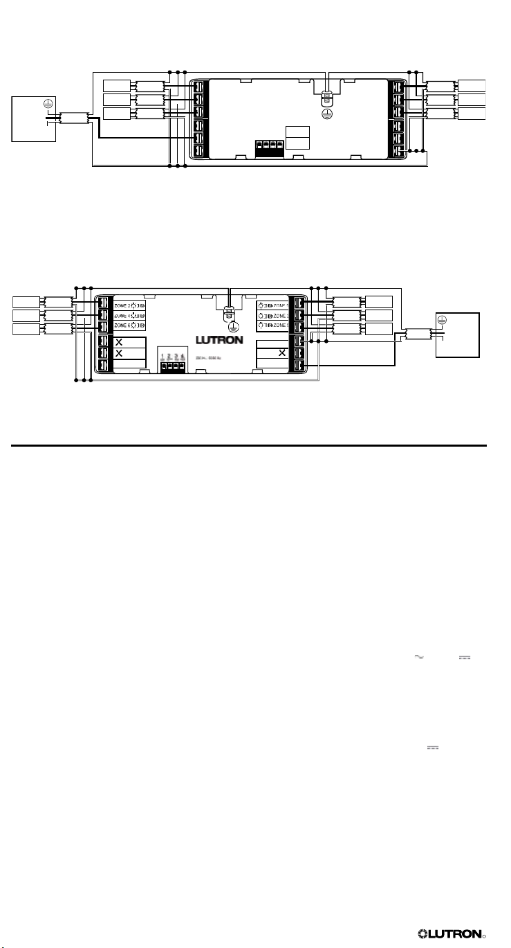
R
N
L
SSA
GRX-3106-CE
ZONE: 40 - 800 W/VA
10 A 2300 W/VA
Coopersburg, PA 18036 USA
:
ZONE 4
ZONE 6
HOT/LIVE
SSA
CU WIRE ONLY
ZONE 2
Class 2
1 2 3 4
ZONE 3
ZONE 5
NEUTRAL
ZONE 1
USA
CLASS 2
IEC
PELV
Conexiones de Voltaje de Línea/Alimentación para los modelos GRX* y GRX-AU*
(se muestra una Unidad de 6 Zonas)
Tierra/masa del panel de distribución
Panel de
distribución
Vivo
2 #12 AWG
N
Alimentación de
entrada del panel
de distribución
Carga 2
Carga 4
Carga
2 #12 AWG
2 #12 AWG
6
2 #12 AWG
2 #12 AWG
2 #12 AWG
2 #12 AWG
Neutro del panel de distribución
Conexiones de Línea de Voltaje/Alimentación para los Modelos GRX-CE*
(se muestra una Unidad de 6 Zonas)
Tierra/masa del panel de distribución
Carga 2
Carga 4
Carga 6
2 2,5 mm
2 2,5 mm
2
2
2
2 2,5 mm
* Para cableado de fase a fase y alimentación Delta, consulte a Lutron.
2
Carga 1
2 2,5 mm
2
Carga 3
2 2,5 mm
2
2 2,5 mm
Carga 5
Neutro del panel
de distribución
Alimentación de entrada del panel
de distribución
Panel de
distribución
2 2,5 mm
2
Vivo
N
Carga 1
Carga 3
Carga 5
Paso 5: Conecte el Cable PELV (Clase 2: EE.UU.)
a la Unidad de control – Opcional
Si su sistema de iluminación usa estaciones de control y/o múltiples unidades de control, se
necesita cableado PELV (Clase 2: EE.UU.) para la alimentación y las comunicaciones entre las
unidades y las estaciones de control.
Información Importante sobre Cableado
• Lutron requieres que se conecte (concatenadas) las unidades y las estaciones de control con
dos pares trenzados para el funcionamiento. Cada par trenzado en el enlace cableado PELV
(Clase 2: EE.UU.) debe consistir en dos conductores trenzados 1,0 mm2.
• Use cable PELV (Clase 2: EE.UU.) adecuadamente certificado. Por una descripción de los tipos
de cable recomendados, consulte “Cables PELV (Clase 2: EE.UU.)” en la página 3.
• Realice la instalación de acuerdo con todos los códigos eléctricos locales y nacionales.
•
Los circuitos de las estaciones de control están clasificados como circuitos Clase 2 (EE.UU.) y
circuitos PELV (IEC). Si no se especifica lo contrario los voltajes no superan los 24 V o 15 V .
Como circuitos de Clase 2 cumplen con los requisitos de NFPA 70®, National Electrical Code®
(NEC®). Como circuitos PELV cumplen con los requisitos de IEC 60364-4-41, VDE 0100 Parte
410, BS7671:1992 y otras normas equivalentes. Los circuitos externos conectados a la entrada,
salida, RS232, Ethernet, DMX512 y otros bornes de comunicaciones o estaciones de control,
deben ser suministrados por una fuente listada Clase 2 o satisfacer los requisitos para circuitos
PELV según corresponda en su país.
• El circuito de bajo voltaje de la unidad de control PELV (Clase 2: EE.UU.) es de 12 V .
• El cable y bloque de bornes PELV (Clase 2: EE.UU.) deben tener una separación de los cables
de la línea de voltaje/alimentación de al menos 7 mm.
6 Guía de Instalación de la Unidad de Control GRAFIK Eye® Serie 3000
 Loading...