

Graf AQUA-CENTER SILENTIO Series, SILENTIO 15/4, SILENTIO 25/4, SILENTIO 15/4 with charging pump, SILENTIO 25/4 with charging pump Installation Instructions And Maintenance
Page 1
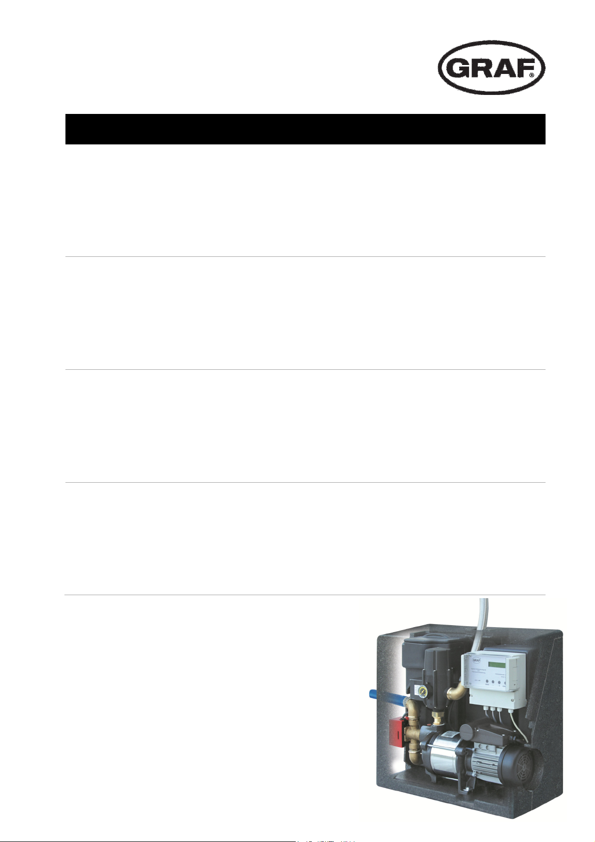
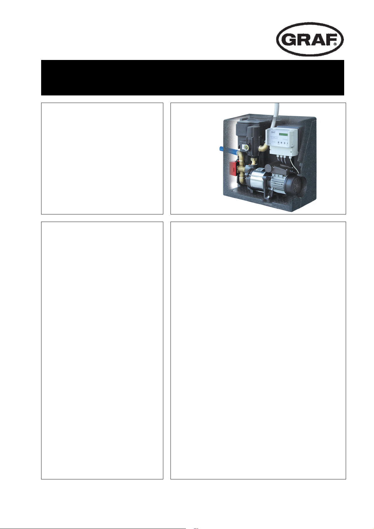
AQUA-CENTER SILENTIO
DE
EN
FR
Anleitung für Einbau und Wartung GRAF TrinkwasserNachspeisung SILENTIO
>> Seite 1-11
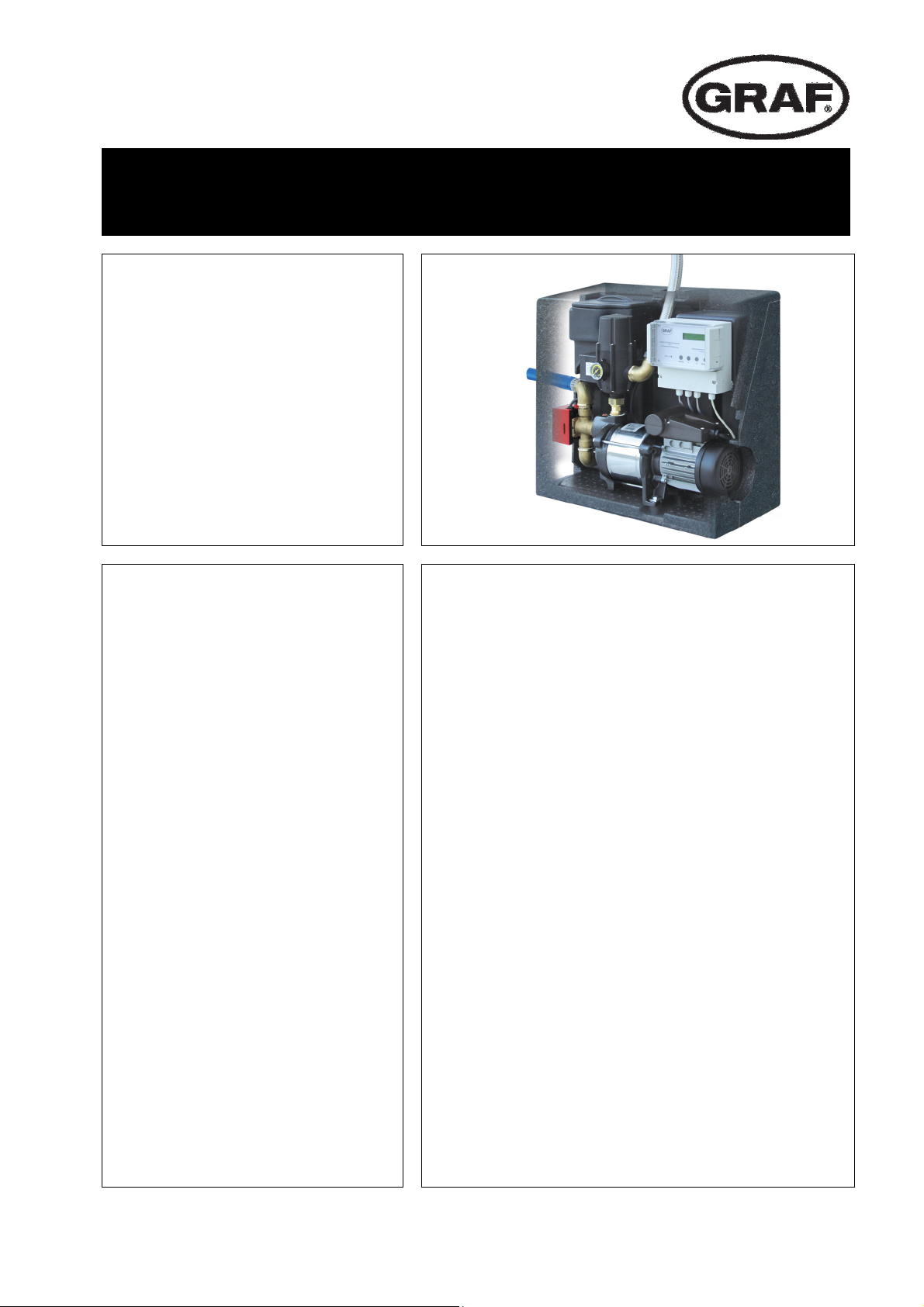
Installation instructions and maintenance for the GRAF
SILENTIO drinking water feeding module
>> Page 12-22
Notice d’installation et d’entretien du coffret d’alimentation
AQUA-CENTER SILENTIO
>> Page 23-33
IT
Istruzioni di installazione e manutenzione console di
alimentazione acqua potabile GRAF SILENTIO
>> Pagina 34-44
Page 2
info@graf-online.de
Inhaltsübersicht
www.graf-online.de
Anleitung für Einbau und Wartung GRAF Trinkwasser-
Nachspeisung SILENTIO
SILENTIO 15/4
Art. Nr. 350209
SILENTIO 25/4
Art. Nr. 350210
SILENTIO 15/4 mit Ladepumpe
Art. Nr. 350211
SILENTIO 25/4 mit Ladepumpe
Art. Nr. 350212
Die in dieser Anleitung
beschriebenen Punkte sind unbedingt zu beachten. Bei Nichtbeachtung erlischt jeglicher
Garantieanspruch. Für alle über
GRAF bezogenen Zusatzartikel
erhalten Sie separate in der
Transportverpackung beiliegende
Einbauanleitungen.
Fehlende Anleitungen sind umgehend bei uns anzufordern.
Eine Überprüfung der Komponenten
auf eventuelle Beschädigungen hat
unbedingt vor der Montage bzw.
Installation zu erfolgen.
Der Einbau ist von einer Fachfirma
durchzuführen.
1. ALLGEMEINE HINWEISE 2
1.1 Sicherheit 2
1.2 Kennzeichnungspflicht 2
2. EINSATZBEREICHE 2
3. TECHNISCHE DATEN 3
3.1 Abmessungen und Gewicht 3
3.2 Steuerung 4
3 Schwimmerventil 4
3.
3.4 3-Wege Umschaltventil 4
3.5 Druck- und Strömungswächter „Controlmatic“ 4
3.6 Pumpe 4
3. TECHNISCHE DATEN 5
4. MONTAGE UND EINBAU 6
4.1 Wandmontage 6
4.2 Anschluss Notüberlauf 7
4.3 Trinkwasseranschluss 7
4.4 Anschluss Saugleitung 8
4.5 Anschluss Druckleitung 8
4.6 Anschluss Datenleitung und Sensorik 9
4.7 Anschluss Zusatzpumpe und Magnetventil für
Opticlean (optional) 9
5. INBETRIEBNAHME 10
6. WARTUNG UND PFLEGE 10
6.1 Wartung 10
6.2 Pflege 10
7. STÖRUNG UND ABHILFEMAßNAHMEN 11
Seite 1 von 44
Page 3

info@graf-online.de
www.graf-online.de
1. Allgemeine Hinweise
1.1 Sicherheit
Bei sämtlichen Arbeiten sind die einschlägigen Unfallverhütungsvorschriften nach BGV C22 zu beachten.
Des Weiteren sind bei Einbau, Montage, Wartung, Reparatur usw. die in Frage kommenden Vorschriften
und Normen zu berücksichtigen. Hinweise hierzu finden Sie in den dazugehörigen Abschnitten dieser
Anleitung.
Die Installation der Anlage bzw. einzelner Anlagenteile muss von qualifizierten Fachleuten durchgeführt
werden.
Bei sämtlichen Arbeiten an der Anlage bzw. Anlagenteilen ist immer die Gesamtanlage außer Betrieb zu
setzen und gegen unbefugtes Wiedereinschalten zu sichern.
Bestimmte Anlagenteile stehen unter Spannung und dürfen nicht geöffnet werden. Arbeiten an elektrischen
Einrichtungen dürfen nur von Elektrofachkräften durchgeführt werden.
Alle Elektrokabel und Anschlüsse müssen sich in einem einwandfreien Zustand befinden. Bei
Beschädigungen darf die Anlage auf keinen Fall in Betrieb genommen werden.
Im Schadensfall kann Wasser aus der Anlage austreten. Das Wasser ist beispielsweise durch Installation
eines Bodenablaufs abzuführen.
Bei unzureichender Befestigung bzw. Montage kann die Anlage herabfallen, es ist für eine ausreichende
Tragkraft der Wand bzw. Halterung zu sorgen.
Die Verwendung, nicht von GRAF freigegebenen Zubehörteilen führt zu einem Ausschluss der
Gewährleistung/Garantie.
1.2 Kennzeichnungspflicht
Das Betriebswasser ist nicht zum Verzehr und zur Körperhygiene geeignet.
Alle Leitungen und Entnahmestellen von Brauchwasser sind mit den Worten „Kein Trinkwasser“ schriftlich
oder bildlich zu kennzeichnen (DIN 1988 Teil 2, Abs. 3.3.2.) um auch nach Jahren eine irrtümliche
Verbindung mit dem Trinkwassernetz zu vermeiden. Auch bei korrekter Kennzeichnung kann es noch zu
Verwechslungen kommen, z.B. durch Kinder. Deshalb müssen alle Brauchwasser – Zapfstellen mit
Ventilen mit Kindersicherung installiert werden.
Die Anlage hat keinen Einfluss auf die Qualität des Betriebswassers.
2. Einsatzbereiche
Die GRAF Trinkwassernachspeisung SILENTIO ist eine Mikroprozessorgesteuerte Schalt-zentrale für
Regenwasser-Nutzungsanlagen. Sie dient der Betriebswasserversorgung von Ein- und kleineren
Mehrfamilienhäusern. Durch die automatische, bedarfsgerechte Nachspeisung mit Trinkwasser ist auch bei
leerem Regenwasserbehälter eine Betriebswasserversorgung gewährleistet.
Betriebswasser kann zum Garten gießen, für die Toilettenspülung, zum Wäsche waschen und als
Putzwasser verwendet werden.
Die GRAF Trinkwasser-Nachspeisung SILENTIO ist zur Montage in frostgeschützten, überflutungssicheren und trockenen Räumen vorgesehen. Weitere Angaben zur Anlagenauslegung, Montage
und Bedienung entnehmen Sie den folgenden Kapiteln.
Seite 2 von 44
Page 4
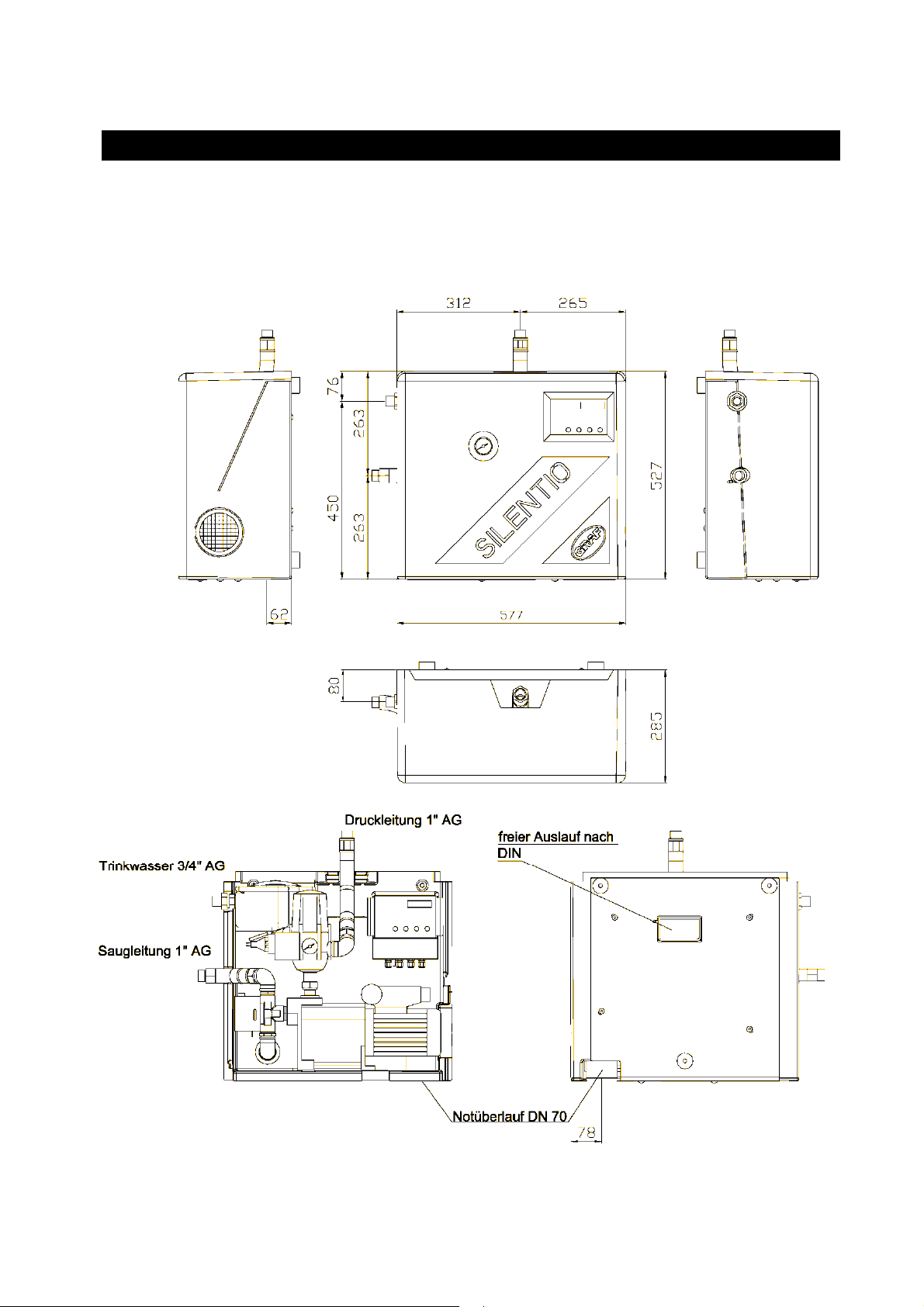
3.1 Abmessungen und Gewicht
Gewicht: ca. 26 kg
info@graf-online.de
www.graf-online.de
3. Technische Daten
Seite 3 von 44
Page 5

info@graf-online.de
k muss ein Druckminderer
3
3
www.graf-online.de
3. Technische Daten
3.2 Steuerung
Die technischen Daten entnehmen Sie bitte der beiliegenden Bedienungsanleitung.
3.3 Schwimmerventil
Betriebstemperatur 30°C max.
Betriebsdruck
Druckfluss max. abhängig vom Leitungsdruck zwischen 1,2 und 3,6 m
Anschlüsse
3.4 3-Wege Umschaltventil
Spannung / Frequenz 230 V / 50Hz
Leistung 6 W (bei Ventilbewegung)
Durchfluss max. 16 m3/h
Öffnungszeit ca. 10 sek
Schließzeit ca. 5 sek
Druck max. 10 bar
Zulässiger Differenzdruck 0,7 bar
0,3 – 4,5 bar (bei zu starkem Wasserdruc
eingebaut werden)
/4“ AG
/h
3.5 Druck- und Strömungswächter „Controlmatic“
Spannung / Frequenz 230 V / 50 Hz
Schutzklasse IP 44
Durchflussmenge max. 10 m3/h
Durchflussmenge min. 0,1 m3/h
Betriebsdruck max. 10 bar
Einschaltdruck min. 1,5 bar
Einschaltdruck max. 2,6 bar
Wiederinbetriebnahme nach Trockenlauf der Pumpe durch Betätigung der „RESET“ Taste möglich.
Sind in der Anlage Druckstöße durch schnell schließende Armaturen (z. B. Magnetventile in
Hochdruckreinigern) zu erwarten, halten Sie bitte Rücksprache mit Fa. GRAF.
3.6 Pumpe
Antrieb
Einphasen-Wechselstrommotor 220-240 V / 50 Hz mit eingebautem
Überlastschutz, IP 44, Isolationsklasse F.
3.6.1 SILENTIO 15/4
istungsaufnahme 660 W
Le
Förderhöhe max. 35 m
Druck max. 3,5 bar
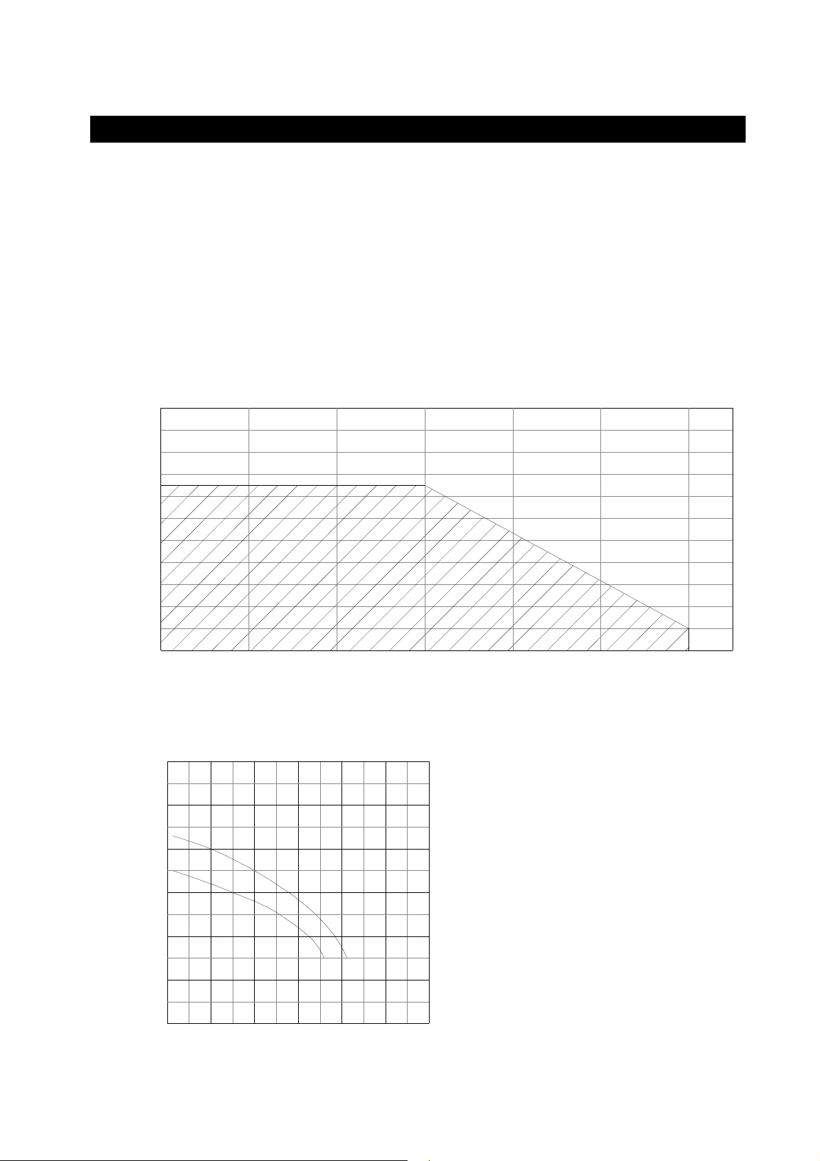
Fördermenge max. 3600 l/h (siehe auch Diagramm 2)
Saughöhe max. 6 m
Sauglänge max. 15 m
Bezüglich Saughöhe als Funktion der Sauglänge siehe auch Diagramm 1.
Seite 4 von 44
Page 6
info@graf-online.de
www.graf-online.de
3. Technische Daten
3.6.2 SILENTIO 25/4
Leistungsaufnahme 800 W
Förderhöhe max. 43 m
Druck max. 4,3 bar
Fördermenge max. 4200 l/h (siehe Diagramm 2)
Saughöhe max. 6 m
Sauglänge 15 m
Bezüglich Saughöhe als Funktion der Sauglänge siehe auch Diagramm 1.
Saughöhe als Funktion der Sauglänge
20
S
a
18
u
16
g
14
l
12
ä
10
n
8
g
e
m
6
4
2
funktioniert
funktioniert nicht
(Tauchpumpe einsetzen)
0 1 2 3
Saughöhe m
Fördermenge in Abhängigkeit zur Förderhöhe
60
F
50
ö
r
d
40
e
r
30
h
Superinox 25/4
Superinox 15/4
ö
20
h
e
10
m
10 2 4 65
3
Fördermenge m³/h
4 5
6
Seite 5 von 44
Page 7
info@graf-online.de
www.graf-online.de
4. Montage und Einbau
Die GRAF Trinkwasser-Nachspeisung SILENTIO aus der Transportverpackung nehmen, im gleichen
Karton befindet sich auch das Zubehör. Die gesamte Anlage sofort auf eventuelle Beschädigungen
überprüfen. Beschädigungen müssen vor der Montage gemeldet werden.
4.1 Wandmontage
Die GRAF Trinkwasser-Nachspeisung SILENTIO ist zur Aufhängung (oberhalb der Rückstauebene) in
frostgeschützten, überflutungssicheren und trockenen Räumen vorgesehen.
Bei der Standortwahl ist zu berücksichtigen, dass für eventuelle Einstell- und Wartungsarbeiten oberhalb
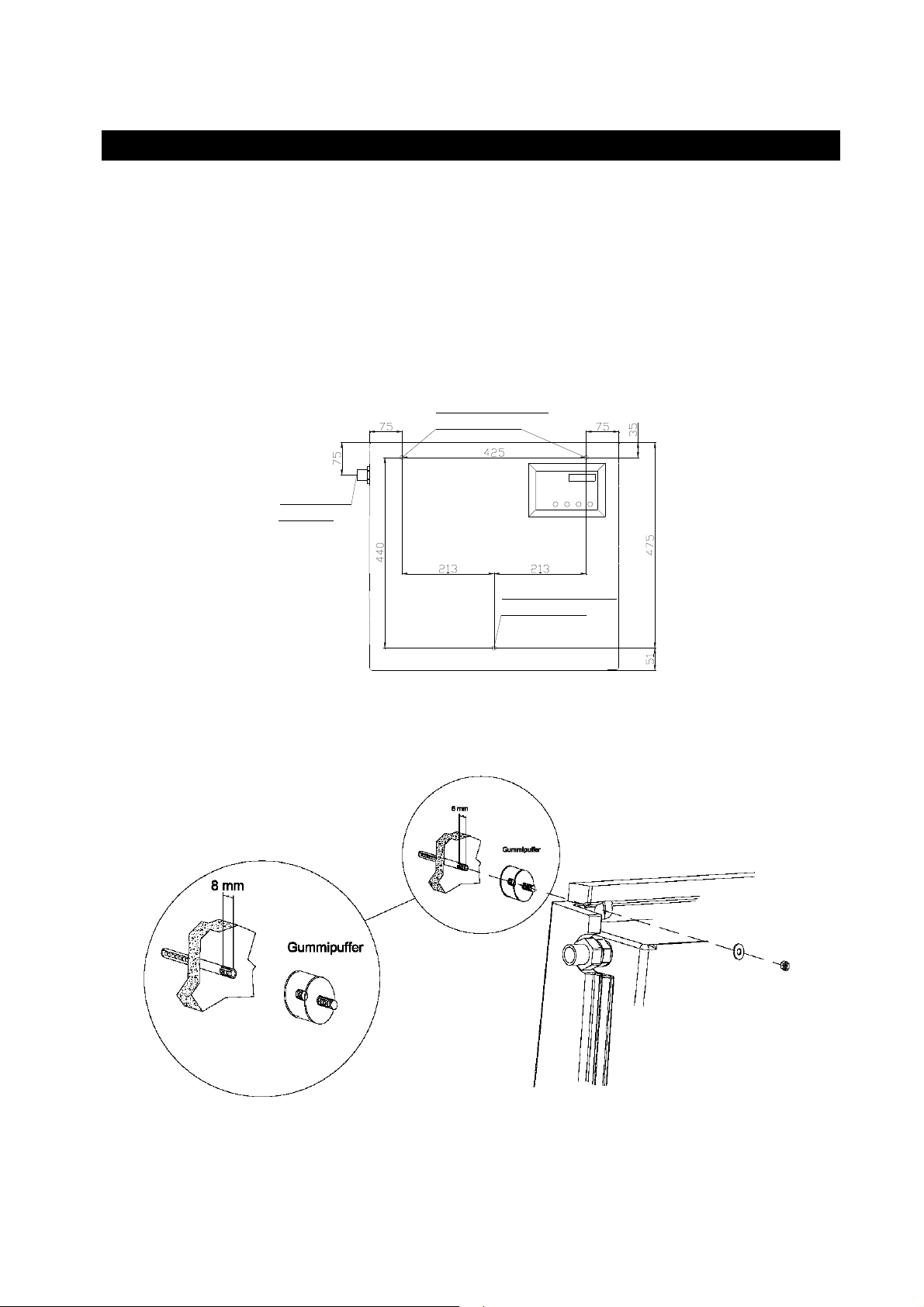
der Anlage noch ca. 50 cm Platz zur Verfügung stehen muss. Die vorgesehene Wand muss geeignet sein,
das Anlagengewicht im gefüllten Zustand von ca. 45 kg, zu tragen.
Bohrbild:
Trinkwasser
anschluß
obere Befestigung,
Bohrer 10 mm
untere Befestigung,
Bohrer 10 mm
Die zu bohrenden Punkte laut Bohrbild an der gewünschten Wand einzeichnen und mit einem 10er Bohrer
die Befestigungslöcher mit einer Tiefe von ca. 60 mm bohren. Die beiliegenden Dübel einsetzen und die
Stehbolzen mit ca. 8 mm Überstand einschrauben. Auf die oberen Stehbolzen werden die beiden
Gummipuffer mit Innen/Außengewinde, auf den unteren der Gummipuffer mit 2 x Innengewinde
aufgeschraubt.
Seite 6 von 44
Page 8
info@graf-online.de
Achtung:
www.graf-online.de
4. Montage und Einbau
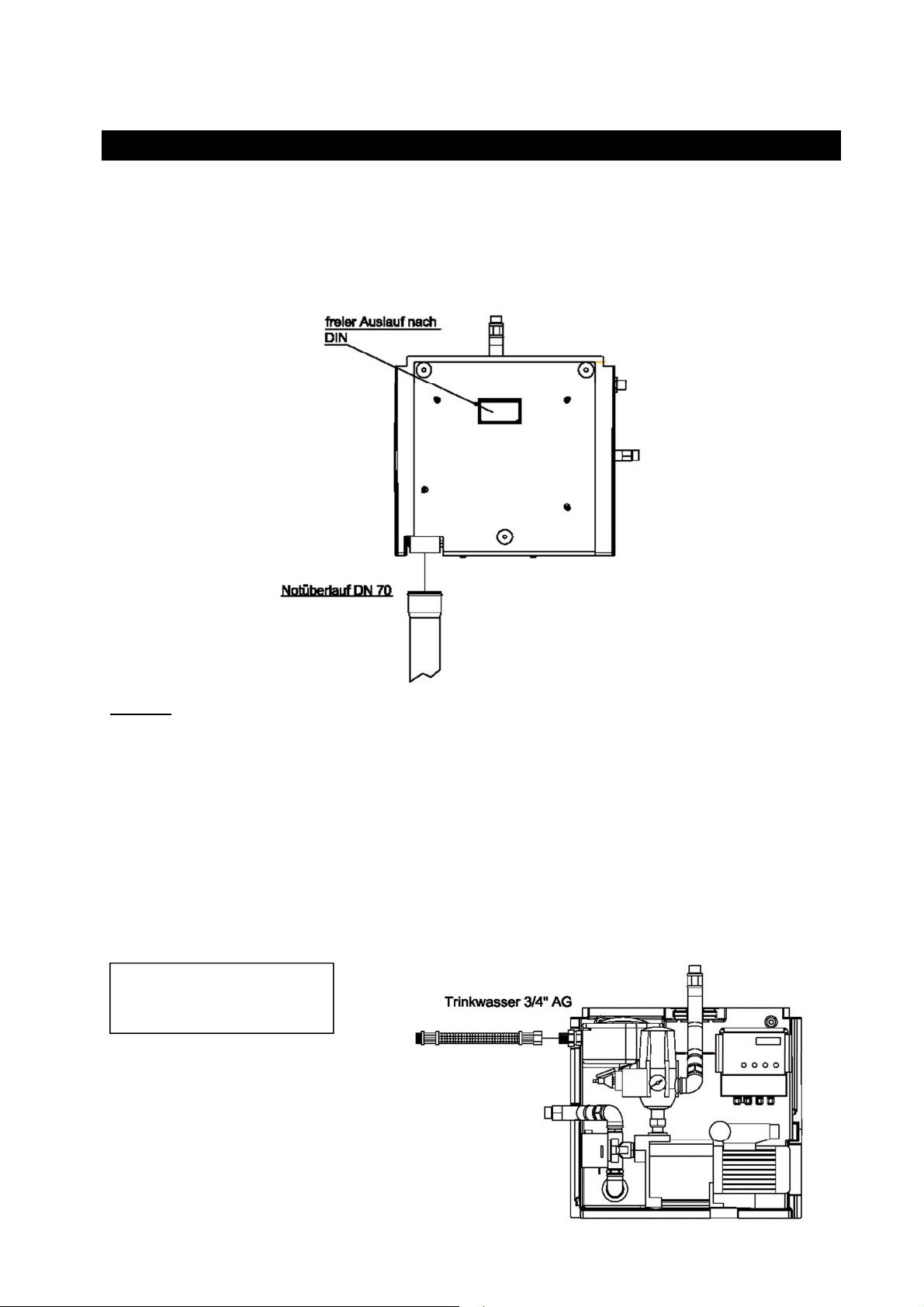
4.2 Anschluss Notüberlauf
Der Notüberlauf wird mit handelsüblichem DN 70 Rohren hergestellt. In Räumen mit Bodenablauf ist es
ausreichend das überlaufende Wasser ohne Anschluss an die Kanalisation aus der Nachspeiseeinheit
herauslaufen zu lassen, da im Normalbetrieb kein Wasser austritt. Ist kein Bodenablauf vorhanden, wird
der Notüberlauf an das Abwassernetz angeschlossen. Bei Veränderungen am Notüberlauf erlischt die
DVGW-Zulassung, eine einwandfreie Funktion kann dann nicht mehr garantiert werden.
Wichtig:
In dem Nachspeisebehälter ist bereits ein Siphon integriert, daher ist hier kein zusätzlicher Siphon
zu installieren.
4.3 Trinkwasseranschluss
Zur Verbindung des Schwimmerventils mit dem Trinkwassernetz empfehlen wir die Installation mit einem
¾“ Panzerschlauch. Beim Anschließen der Frischwasserzuleitung muss ein verdrehen des Ventils
unbedingt verhindert werden, da eine einwandfreie Funktion ansonsten nicht gewährleistet ist. Ein
zusätzliches Absperrventil erleichtert zukünftige Wartungsarbeiten.
Vor der Installation muss die Trinkwasserleitung gut durchgespült werden. Ein bauseits zu montierender
Feinfilter garantiert eine langfristige Funktion des Schwimmerventils und des 3-Wege Umschaltventils.
Leitungsdruck Stadtnetz
max. 0,3 – 4,5 bar!
Seite 7 von 44
Page 9
info@graf-online.de
www.graf-online.de
4. Montage und Einbau
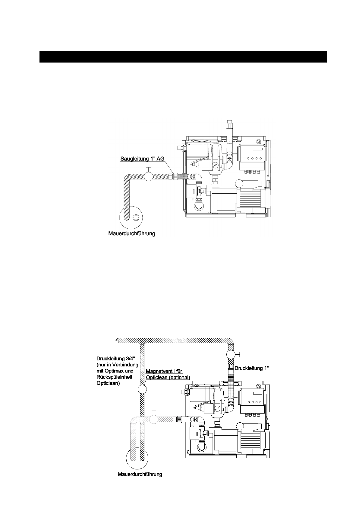
4.4 Anschluss Saugleitung
Die 1“ Saugleitung wird in einem Leerrohr stetig steigend, ohne Durchbiegungen zum Installationsort der
Trinkwassernachspeisung geführt. Ist dies nicht möglich, ist an der höchsten Stelle der Saugleitung ein
Entlüftungsventil zu installieren.
Der Anschluss an die Nachspeiseeinheit SILENTIO erfolgt oberhalb des 3-Wege-Umschaltventils am
90° Messingbogen
mittels des
beiliegenden
1“ Panzerschlauches.
Die Installation eines
Absperrhahnes in der
Saugleitung
erleichtert eventuelle
Wartungsarbeiten.
4.5 Anschluss Druckleitung
Der Anschluss der Druckleitung erfolgt am 90° Messingbogen am Druck- und Strömungswächter mittels
des zweiten beiliegenden 1“ Panzerschlauches, dieser wird nach oben aus dem Gerät herausgeführt. Die
weitere Installation zu den einzelnen Verbrauchern erfolgt bauseits mit handelsüblichem Installationsrohr
(kein Kupferrohr verwenden). Ein Absperrhahn in der Druckleitung erleichtert eventuelle Wartungsabreiten.
Seite 8 von 44
Page 10
info@graf-online.de
Wichtig:
www.graf-online.de
4. Montage und Einbau
Für einen störungsfreien Betrieb der Komplettanlage ist es außerordentlich wichtig,
dass der Rückspülfeinfilter (optionales Zubehör) ausschließlich druckseitig installiert
wird.
Ein nicht fachgerechter Einbau kann hier zu verspäteten Fehlfunktionen
(z.B. Luftansaugung o.ä.) führen.
4.6 Anschluss Datenleitung und Sensorik
Die Datenleitung wird vom Erdtank durch das Leerrohr zur Nachspeisung SILENTIO verlegt und am freien
Chinchstecker angeschlossen. Die Sensorik im Behälter wird laut der beiliegenden Installationsanleitung
für die Steuerung angeschlossen.
4.7 Anschluss Zusatzpumpe und Magnetventil für Opticlean (optional)
Das Magnetventil zur automatischen Ansteuerung der Reinigungseinheit Opticlean sowie eine mögliche
Zusatzpumpe können über die Mikroprozessorsteuerung geschaltet werden. Eine entsprechende
Montageanleitung finden Sie in der beiliegenden Installationsanleitung für die Steuerung. Benutzen Sie
ausschließlich von GRAF freigegebene Ventile und Pumpen, ansonsten kann es zu Schäden in der
Elektronik der Steuerung kommen.
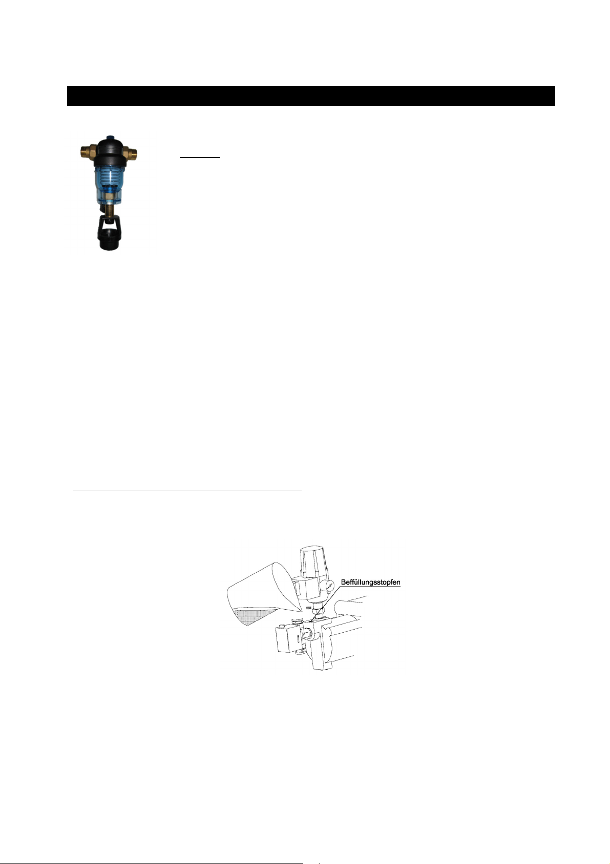
Vor Inbetriebnahme der Anlage müssen alle zu- und abführenden Leitungen durchgespült werden.
Teilchen > 2 mm können zu schweren Schäden an der Pumpe und anderer Bauteile führen.
Nehmen Sie die Pumpe niemals trocken in Betrieb!
Schrauben Sie den Einfüllstutzen am Pumpengehäuse auf und füllen Sie den Pumpenkörper mit Wasser.
Seite 9 von 44
Page 11

info@graf-online.de
www.graf-online.de
5. Inbetriebnahme
Anschließend wird die Saugleitung ebenfalls mit Wasser befüllt. Hierzu wird am Zisternen-seitigen Ende
ein Schlauch an die Saugleitung (Saugkorb entfernen) angeschlossen und ein Verbraucher im Haus
geöffnet. Stellen Sie sicher, dass das rote 3-Wege-Ventil auf Automatik [A] steht. Durch öffnen des
Zulaufventils am Befüllschlauch die gesamte Anlage befüllen, bis am geöffneten Verbraucher Wasser
blasenfrei austritt. Mit dieser Vorgehensweise wird die Anlage zuverlässig entlüftet und ist sofort
betriebsbereit. Jetzt den Netzstecker der Steuerung in eine Steckdose (230 V / Absicherung 16 A träge)
einstecken, die Anlage läuft sofort an. Sollte die Pumpe nicht anlaufen bzw. nach kurzer Zeit wieder
ausgehen ist der „Reset Knopf“ am Controlmatic zu drücken. Dieser Vorgang ist so lange zu wiederholen,
bis am Verbraucher das Wasser blasenfrei austritt, anschließend den Verbraucher schließen, die Pumpe
erreicht ihren maximalen Druck und schaltet automatisch ab.
Ist ein befüllen der Saugleitung wie oben beschrieben nicht möglich, kann diese auch vom Installationsort
der SILENTIO befüllt werden, dabei muss das Fußventil der Saugleitung im Behälter geöffnet werden. Die
Befüllung muss so lange erfolgen, bis am zisternenseitigen
Ende Wasser austritt. Anschließend die Anlage wie oben beschrieben in Betrieb nehmen.
Zum Abschluss der Inbetriebnahme wird der Trinkwasserzulauf zum Nachspeisebehälter geöffnet.
Dadurch füllt sich der Behälter, bevor das Wasser durch den Überlauf abfließt muss das Schwimmerventil
den Zulauf verschließen. Ist dies nicht der Fall muss das Ventil durch nachjustieren des
Styroporschwimmers eingestellt werden.
6. Wartung und Pflege
6.1 Wartung
Die komplette Anlage muss in regelmäßigen Abständen (ca. alle 3 – 4 Monate) gewartet werden. Bei jeder
Wartung sind alle Schraubverbindungen auf Dichtheit zu prüfen. Des Weiteren sollte der Sitz und die
Funktion des Schwimmerventils im Nachspeisebehälter kontrolliert werden. Wird die Anlage über einen
längeren Zeitraum nicht genutzt oder besteht Frostgefahr ist die Pumpe und die Controlmatic zu entleeren.
Eine Zwischenlagerung darf nur an einem trockenen gut belüfteten Ort erfolgen.
6.2 Pflege
Zur Pflege und Reinigung der Anlage ist es ausreichend diese mit einem feuchten Tuch abzuwischen, bei
gröberen Verunreinigungen können auch sanfte Reiniger eingesetzt werden. Auf keinen Fall mit
Lösungsmittel oder lösungsmittelhaltigen Reinigern säubern.
Seite 10 von 44
Page 12
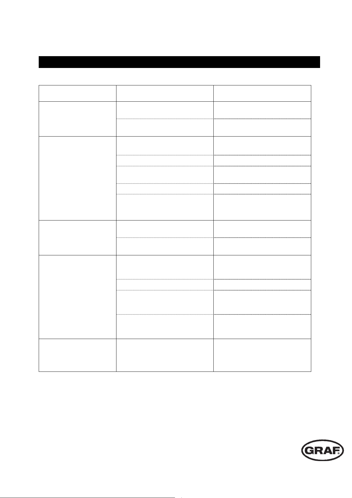
7. Störung und Abhilfemaßnahmen
Reparaturen an elektrischen Anlagenteilen dürfen nur von Fachfirmen durchgeführt werden!
Störung Ursache Fehlerbehebung
Pumpe läuft nicht an
Pumpe saugt nicht an
Pumpe schaltet nicht ab
- Netzspannung fehlt
- Pumpenrad blockiert
- Saugventil nicht im Wasser
- Netzstecker einstecken oder
Netzspannung überprüfen
- Pumpe von einem Fachbetrieb
warten oder reinigen lassen
- Saugventil unterhalb des
Wasserspiegels anbringen
- Pumpenrad ohne Wasser - Anlage mit Wasser befüllen
- Luft in Saugleitung
- Anlage entlüften, Dichtheit der
Anlage prüfen
- Saugkorb verstopft - Saugkorb reinigen
- max. Saughöhe, bzw. Länge der
Saugleitung wurde überschritten
- möglicherweise Verbraucher
offen
- Druckleitung bzw. Verbraucher
undicht
- Saughöhe überprüfen, ggf.
Standort der Pumpe ändern
oder Tauchpumpe einsetzen
- Verbraucher schließen
- Druckleitung bzw. Verbraucher
abdichten
- Saughöhe überprüfen, ggf.
- Saughöhe zu hoch
Standort der Pumpe ändern
oder Tauchpumpe einsetzen
Fördermenge ungenügend
Thermoschalter schaltet
Pumpe ab
- Saugkorb verschmutzt - Saugkorb reinigen
- Verschmutzung einzelner
Anlagenteile
- Alle Anlagenteile reinigen,
Pumpe von Fachbetrieb warten
lassen
- Förderhöhe überprüfen, ggf.
- Förderhöhe zu hoch
Standort der Pumpe ändern
oder größere Pumpe einsetzen
- Pumpe von einem Fachbetrieb
- Motor ist durch Verschmutzung
im Pumpengehäuse überlastet
warten und reinigen lassen
- Ansaugen von Fremdstoffen
verhindern
www.graf.info
Seite 11 von 44
2018-09
Page 13
info@graf-online.de
Table of contents
www.graf-online.de
Installation instructions and maintenance for the GRAF
SILENTIO drinking water feeding module
SILENTIO 15/4
Order Nr. 350209
SILENTIO 25/4
Order Nr. 350210
SILENTIO 15/4 with charging pump
Order Nr. 350211
LENTIO 25/4 with charging pump
SI
Order Nr. 350212
The points described in these
instructions must be followed
correctly. If not correctly ob-served,
any right to claim on the guarantee
may be re-fused. For all additional
GRAF articles purchased there are
separate installation instructions
enclosed in the transportation
packing.
Any missing instructions must be
requested directly from us.
A complete check of all the
items/components for possible
damage must be carried out before
the assembly or installation begins.
The installation must be carried out in
a professional manner.
1. GENERAL NOTES
1.1 Safety
1.2 Identification obligation
2. APPLICATION
3. TECHNICAL DATA
3.1 Dimensions and weight
3.2 System control
3.3 Float valve
3.4 3 way switch-over valve
3.5 Pressure and flow rate sensor „Controlmatic“
3.6 Pump
4. INSTALLATION AND ASSEMBLY
4.1 Wall assembly
4.2 Emergency overflow connection
4.3 Drinking water connection
4.4 Suction pipe connection
4.5 Pressure hose connection
4.6 Data cable and sensor connection
4.7 Connection of the Opticlean additional pump and
solenoid valve (optional)
13
13
13
13
14
14
15
15
15
15
15
17
17
18
18
19
19
20
20
5. COMMISSIONING
6. SERVICE AND CARE
6.1 Service
6.2 Care
7. FAULT FINDING AND CORRECTIVE ACTION
page 12 of 44
20
21
21
21
22
Page 14

info@graf-online.de
www.graf-online.de
1. General notes
1.1 Safety
The relevant accident prevention regulations according to BGV C22 must be observed during all work.
Furthermore, when carrying out assembly and installation work, inspection, maintenance and repairs, all
work regulations and norms must be followed. You will find the advice in the appropriate sections of these
instructions.
The installation of the system and/or single equipment parts must be carried out by a professional worker.
The complete system must always be out of operation and guarded against unauthorized use when
carrying out work on the plant or parts of the system.
Certain parts of the system are under electrical voltage and must not be opened. Working on the electrical
system may only be carried out by a professional electrician.
All electrical wiring and connections must be in faultless condition. If damaged, the system may under no
circumstances be brought into operation.
In case of damage, the equipment may lose water. The equipment can be safeguarded by the installation a
floor drainage system.
In the case of inadequate fastening or poor assembly conditions, the equipment may fall, so it is important
to check that the wall material and the fixing brackets are adequate for the load.
The use of accessories that have not been approved by GRAF results in the exclusion of the
warranty/guarantee.
1.2 Identification obligation
The water in these systems is not suitable for consumption or personal hygiene.
All pipe work and outlets of the water systems are to be labelled with the words “Not drink-ing water”
either in words or graphically (German norm DIN 1988 Part 2, paragraph 3.3.2.) so that after years of use,
an accidental connection to the drinking water system is pre-vented. Even when correctly labelled it may
possibly be mistaken, for example by children. For this reason, all the outlets of the systems process water
must be fitted with child-proof locks.
The system has no influence on the quality of the process water.
2. Application
The GRAF drinking water feeding module SILENTIO is a micro-processor controlled manage-ment system
for rain water. It is intended for service water in private homes and small apartment developments. By
using an automatic back-up supply from mains water that deliv-ers water to the tank if required, the rain
water system guarantees the supply of process wa-ter.
The process water may be used to water the garden, to flush the toilet, for washing clothes and as
conventional cleaning water.
The GRAF SILENTIO drinking water feeding module must be installed in a frost free and dry environment
that is above any flood levels. Further information regarding the systems specifications, assembly and
operation are detailed in the following sections.
page 13 of 44
Page 15
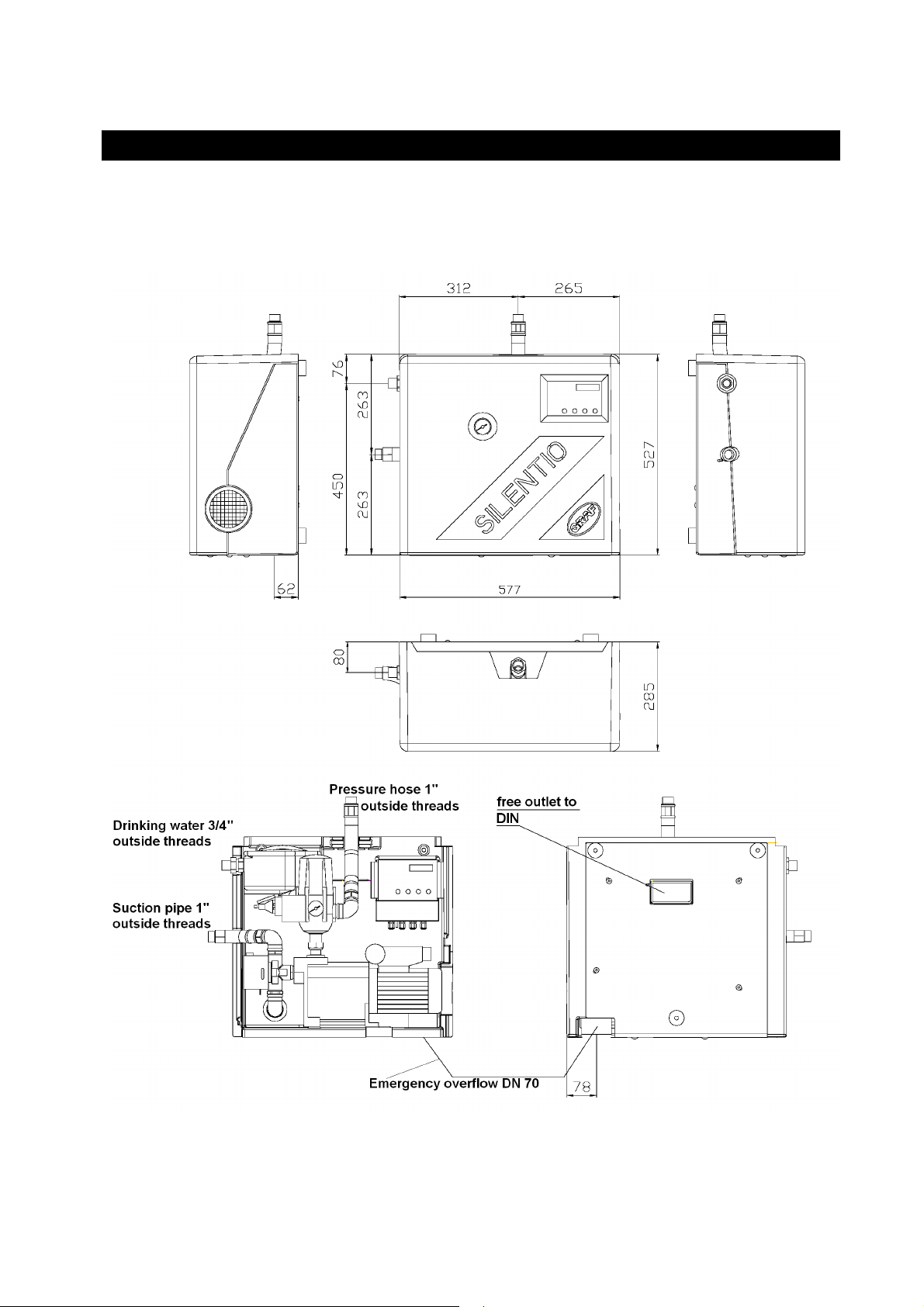
3.1 Dimensions and weight
Weight: about 26 kg
info@graf-online.de
www.graf-online.de
3. Technical Data
page 14 of 44
Page 16

info@graf-online.de
water pressure a pressure reducer must
3
3
Hz with integrated overload
www.graf-online.de
3. Technical Data
3.2 System control
Please find the technical data from the enclosed operating instructions.
3.3 Float valve
Operating temperature 30°C max.
Operating pressure
Flow rate max. depending on the line pressure between 1.2 and 3.6 m
Connections
3.4 3 way switch-over valve
Voltage / Frequency 230 V / 50Hz
Output 6 W (bei Ventilbewegung)
Flow rate max. 16 m3/h
Opening time ca. 10 sek
Close time ca. 5 sek
Pressure max. 10 bar
Allowable pressure differential 0.7 bar
0.3 – 4.5 bar (if there is too strong
be installed!)
/4“ AG
/ h
3.5 Pressure and flow rate sensor „Controlmatic“
Voltage / Frequency 230 V / 50 Hz
Protection classification IP 44
Flow rate max. 10 m3/h
Flow rate min. 0.1 m3/h
Operating pressure max. 10 bar
Opening pressure min. 1.5 bar
Opening pressure max. 2.6 bar
Restarting after dry running the pump is possible by means of the "RESET" button.
If there is a water pressure hammering in the system due to the rapid closing of valves (e.g. solenoid valve
in the high pressure cleaner) then please contact the GRAF Company.
3.6 Pump
Drive unit
Single phase AC motor 220 – 240 V / 50
protection IP 44, isola-tion class F.
3.6.1 SILENTIO 15/4
Power requirement 660 W
Pump head height max. 35 m
Pressure max. 3.5 bar
Pump discharge rate max. 3600 l/h (see also Diagramm 2)
Suction height max. 6 m
Suction length max. 15 m
Concerning suction height as a function of the suction length see also diagram 1.
page 15 of 44
Page 17

info@graf-online.de
www.graf-online.de
3. Technical Data
3.6.2 SILENTIO 25/4
Power requirement 800 W
Pump head height max. 43 m
Pressure max. 4.3 bar
Pump discharge rate max. 4200 l/h (see also Diagramm 2)
Suction height max. 6 m
Suction length max. 15 m
Concerning suction height as a function of the suction length see also diagram 1.
page 16 of 44
Page 18

info@graf-online.de
connection
drill bit 10mm
bit 10 mm
www.graf-online.de
4. Installation and assembly
Remove the GRAF SILENTIO drinking water feeding module from its transport packing; in the same box
are also the other parts and accessories. Firstly, check the whole equipment for any possible damage. Any
damage must be reported before the assembly and installation begins.
4.1 Wall assembly
The GRAF SILENTIO drinking water feeding module must be installed above the back surge level and in a
frost free and dry environment that is above any possible regional flood levels.
When choosing a position for installation it is important to be sure that there is at least 50 cm free space
available above the equipment for any maintenance or adjustment regulation. The wall intended for
mounting must be suitable for supporting the equipment with an approxi-mate maximum weight of 45 kg
when filled with water.
Trinkwasser
Drinkingwater
anschluß
Bohrbild:
Upper fixing drill
obere Befestigung,
Bohrer 10 mm
untere Befestigung,
Lower fixing
Bohrer 10 mm
The holes to be drilled are marked out on the wall using the template and then drilled with a 10 mm
masonry bit, the holes should be approximately 60 mm deep. Insert the enclosed dowel-plugs and then
screw in the stud bolts so that approximately 8 mm remains protruding. Attach the two rubber buffers with
the inside and outside threads to the two upper studs and attach the two rubber buffers with the double
inside threads to the lower studs.
page 17 of 44
Page 19

info@graf-online.de
Attention:
www.graf-online.de
4. Installation and assembly
4.2 Emergency overflow connection
The emergency overflow is to be constructed with commercial 70 mm canalisation pipes. In rooms with
effective floor drains, it would be sufficient in the event of any overflowing water from the back-up unit,
since under normal operating conditions no water will overflow and an extra connection to the sewage
canalisation is not required. If there is no floor drain then it is necessary to install an emergency overflow
that is connected to the sewage network. If there are any changes made to the emergency overflow the
DVGW approval is cancelled as a problem free operation can no longer be guaranteed.
Important:
An emergency overflow is already integrated in the drinking water feeding console, therefore, no
additional overflow is required.
4.3 Drinking water connection
For connecting the float valve to the mains water supply we recommend using a ¾“ reinforced hose for the
installation. Take care when tightening the supply pipe that the valve does not also twist around
problem free operation can no longer be guaranteed. An additional shut-off valve will also make any
future maintenance work less complicated.
Before the installation the mains water pipe system must be well flushed through. A fine filter should be
installed to guarantee a long life and trouble free functioning of the float valve and the 3 way switch-over
valve.
Line pressure from the mains water
max. 0.3 – 4.5 bar!
page 18 of 44
Page 20

info@graf-online.de
www.graf-online.de
4. Installation and assembly
4.4 Suction pipe connection
A 1“ suction pipe is installed in an empty conduit that rises steadily without sagging or bend-ing downward
to the connection at the mains water supply point. If this proves to be not pos-sible then an air bleeding
valve must be installed at the highest point.
The connection to the SILENTIO back-up supply unit is by way of the 3 way switch-over valve which has at
its’ top a brass 90° elbow connection and the enclosed 1” reinforced hose. The installation of a shut-off
valve in the suction pipe will make future maintenance work less complicated.
4.5 Pressure hose connection
The connection of the pressure hose to the brass 90° elbow on the pressure and flow rate sensor using the
2 enclosed 1” diameter reinforced hoses, these are then fed out through the top of the unit. The further
installation to the various individual outlets etc is to be completed with commercial installation pipes (only
plastic, use no copper etc). A shut-off valve installed in the pressure lines make any future maintenance
work less complicated.
page 19 of 44
Page 21

info@graf-online.de
Important:
www.graf-online.de
4. Installation and assembly
To ensure a trouble-free operation of the whole system it is essential, that
the reversible flow filter (optional accessory) is only installed from the
pressure side.
An unprofessional installation can lead to future malfunctions (e.g. air
intake).
4.6 Data cable and sensor connection
The data cables are taken from the tank through the empty conduit to the SILENTIO back-up supply unit
and connected to a free plug socket. The sensor in the tank must be connected to the control unit and
installed according to the enclosed instructions.
4.7 Connection of the Opticlean additional pump and solenoid valve (optional)
The solenoid valve for the automatic operation of the Opticlean cleaning unit and in some cases an
additional pump can be activated over the microprocessor management. The applicable assembly
instructions are found in the enclosed installation instructions for the control unit. Please use only the
valves and pumps that are approved by GRAF otherwise there is the danger of damage to the electronics
and control management system.
5. Commissioning
fore the commissioning of the system all of the inlet and outlet pipes must be thoroughly rinsed through.
Be
Small foreign objects up to 2 mm can cause substantial damage to pumps and other equipment.
Never run pumps without water in the system!
Remove the threaded fill plug from the pumps’ body and completely fill the housing with water.
page 20 of 44
Page 22

info@graf-online.de
www.graf-online.de
5. Commissioning
Then also fill the suction pipe with water. To do this, the cistern side end of a pipe is connected to the
suction pipe (remove the basket) and an outlet in the house is opened. Be sure that the red 3 way valve is
set to automatic [A]. By opening the inlet valve on the filling hose the complete system is filled with water
until the water emerges free of air bubbles. With this method the system is reliably bled of air and is now
ready for operation. Now make the electric connection to the mains plug (230 V / Fused 16 A) and the
system will be running. If the pump does not run or cuts out after a short time, then press the reset button
on the controlmatic. This procedure is to be repeated until the water emerges without air bubbles at the
outlet which is then closed, the pump will reach it’s maximum pressure and stop automatically.
If it is not possible to fill the suction pipe with this method then it is also possible to fill it at the SILENTIO
unit, to do this the flow valve of the suction pipe in the tank must be opened. The filling must continue until
the water emerges at the cistern end. The system may now be put into operation as described above.
Finally the commissioning is competed by opening the mains water supply to the back-up supply tank. This
fills the tank and before the water flows out of the overflow the float valve must close off the inlet. If this
does not happen then the polystyrene float that controls the valve must be adjusted.
6. Service and care
6.1 Service
The complete system must be serviced at regular intervals (approximately every 3 to 4 months). For every
service all of the threaded connections must be checked for leaks. Also the condition of the function of the
float valve for the back-up tank must be checked. If the system has been out of use for a long period or
there has been the danger of frost then the pump and controlmatic should be emptied. Any temporary
storage should only be at a dry and well ventilated location.
6.2 Care
For care and cleaning of the system it is sufficient to use a damp cloth, for more thorough cleaning a mild
detergent may also be used. Under no circumstances should a solvent or cleaning agents containing
solvents be used.
page 21 of 44
Page 23

info@graf-online.de
www.graf-online.de
7. Fault finding and corrective action
Working on the electrical system may only be carried out by a professional electrician!
Fault Cause Corrective action
Pump does not run
Pump does not draw
Pump does not switch off
- No electrical power
- Pump impeller jammed
- Plug into or check the electrical
supply
- Professional pump overhaul or
service and cleaning
- Suction valve should be
- Suction valve is not in the water
brought below the waters
surface
- Pump impeller without water - Fill the system with water
- Air in the suction pipe
- Air bleed the system and check
for leaks
- Blocked suction basket - Clean the suction baske
- Max. Suction height or length of
suction pipe has been exceeded
- Possibly an outlet is open (water
left running)
- Pressure hose or outlet is
leaking
- Check the suction height or
change the pump position or use
a submersible pump
- Close the outlet
- Repair the leaking pressure
hose or outlet
Pump discharge rate
insufficient
Thermal circuit breaker
shuts down the pump
- Check the suction height or
- Suction height too high
change the pump position or use
a submersible pump
- Blocked suction basket - Clean the suction basket
- Clean all system components
- Dirt in system equipment
and overhaul or service the
pump from professionals
- Check the pump head height , or
- Pump head height too high
change the pump position or use
a larger pump
- Professional pump overhaul or
- Overloading due to dirt in the
motor housing
service and cleaning
- Prevent the drawing in of dirt
and foreign objects
www.graf.info
page 22 of 44
2018-09
Page 24

Notice d’installation et d’entretien du coffret
Sommaire
d’alimentation AQUA-CENTER SILENTIO
SILENTIO 15/4
Réf. 350209
SILENTIO 25/4
Réf. 350210
SILENTIO 15/4 avec pompe
immergée
Réf. 350211
SILENTIO 25/4 avec pompe
immergée
Réf. 350212
info@graf-online.de
www.graf-online.de
Afin de garantir le bon fonctionnement et la longévité de votre
installation, il est important de
respecter précisément les instructions de mise en place du
producteur. Tout manquement à ces
règles annulera systémati-quement la
garantie.
Les guides manquant doivent
immédiatement nous être demandés.
Avant d’installer le coffret
d’alimentation, il est important de
vérifier qu’aucun composant n’a été
endommagé lors du transport.
L’installation doit être effectuée par
un installateur professionnel.
1. GÉNÉRALITÉS
1.1 Sécurité
1.2 Marquage
2. CHAMPS D´ACTION
3. SPECIFICATIONS TECHNIQUES
3.1 Dimensions
3.2 Réglages
3.3 Vanne à flotteur
3.4 Electrovanne 3 voies
3.5 Kit d’automatisation „Controlmatic“
3.6 Pompe
4. INSTALLATION ET MONTAGE
4.1 Fixation sur le mur
4.2 Branchement du trop-plein
4.3 Branchement de l’eau potable
4.4 Branchement du tuyau de tirage
4.5 Branchement du refoulement
4.6 Branchement des câbles de données et du
transducteur
4.7 Branchement d’une pompe immergée (option)
5. MISE EN MARCHE
6. ENTRETIEN
7. PANNES ET MÉSURES DE DÉPANNAGE
24
24
24
24
25
25
26
26
26
26
26
28
28
29
29
30
30
31
31
32
32
33
Seite 23 von 44
Page 25

info@graf-online.de
www.graf-online.de
1. Généralités
1.1 Sécurité
Prendre toutes les précautions nécessaires lors de l’installation, d’un entretien ou d’une réparation. Vous
trouverez des indications plus spécifiques dans le reste de la notice.
L’installation doit se faire par un installateur professionnel. Avant tous travaux, l’installation complète doit
être sécurisée et mise hors service.
Certains composants du coffret sont sous tension et ne doivent pas être ouverts. Les travaux sur les
installations électriques ne peuvent être réalisés que par des électriciens qualifiés.
Tous les câbles électriques et les raccords doivent être dans un état irréprochable. Si ce n’est pas le cas,
le coffret ne doit pas être mis en fonction.
Pour éviter une inondation de la cave, pouvant provenir d’une intervention inappropriée ou d’un cas de
force majeur, il est conseillé d’installer le coffret AQUA-CENTER SILENTIO dans une cave équipée d’une
évacuation au sol.
Si la fixation du coffret sur le mur n’est pas sûr, il faut prévoir des renforts aux fixations fournies.
GRAF décline toute prise en charge sous garantie en cas d’utilisation d’accessoires non conformes.
1.2 Marquage
L’eau récupérée n’est en aucun cas destinée à la boisson ou à l’hygiène !
Afin d’éviter toute confusion, toutes les sorties d’eau de pluie doivent être signalées par la men-tion écrite
ou en image « Eau non-potable ». Tous les points d’approvisionnement doivent être équipés de vannes «
sécurité-enfant ».
Le coffret n’a pas d’influence sur la qualité des eaux mises à dispositions.
2. Champs d´action
L
e coffret d’alimentation AQUA-CENTER SILENTIO est une centrale de gestion automatisée par micro-
processeur. Il est utilisé pour alimenter une maison individuelle ou un immeuble.
Dans le cas où la cuve serait à sec, l’alimentation en eau potable du réseau est gérée automatiquement.
L’eau récupérée peut être utilisée pour le jardin, les toilettes, les machines à laver et comme eau de
lavage.
Le coffret doit être installé à l’abris du gel et des inondations.
Seite 24 von 44
Page 26

3.1 Dimensions
Poids: environ 26 kg
info@graf-online.de
www.graf-online.de
3. Specifications techniques
Eau potable 3/4“
Tuyau de tirage 1“
Tuyau de refoulement 1“
Sortie électrique
Surverse de sécurité
Seite 25 von 44
Page 27

3. Specifications techniques
3
3.2 Réglages
Les détails techniques sont donnés ci-après.
3.3 Vanne à flotteur
info@graf-online.de
www.graf-online.de
Température d’utilisation
Pression d’utilisation 0,3 – 4,5 bar (installer un réducteur de pression si nécessaire)
Débit max.
Raccord
3.4 Electrovanne 3 voies
Tension / Fréquence 230 V / 50Hz
Puissance 6 W (pendant un changement de position)
Débit max.: 16 m3/h
Durée d’ouverture t
Durée de fermeture
Pression max. 10 bar
Différence de pression tolérée 0,7 bar
3.5 Kit d’automatisation „Controlmatic“
Tension / Frequence
Fusible de protection: IP 44
Débit max. 10 m3/h
Débit min. 0,1 m3/h
Pression d’utilisation max. 10 bar
Pression de démarrage min. 1,5 bar
Pression de démarrage max. 2,6 bar
30°C max.
dépend du débit d’alimentation compris entre 1.2 et 3.6m³/h
/4“ filetage externe
environ 10 sec
environ 5 sec
230 V / 50 Hz
La remise en marche de la pompe après une marche à sec est possible en appuyant sur
Si des chocs de pressions dus à la fermeture de robinet surviennent, veuillez consulter la
société GRAF.
3.6 Pompe
Transmission:
3.6.1 SILENTIO 15/4
Puissance nominale 660 W
Hauteur de refoulement max.
Pression de refoulement max. 3,5 bar
Débit de refoulement max. 3600 l/h (voir diagramme 2)
Hauteur de tirage max. 6 m
Longueur de tirage max. 15 m
La hauteur de tirage est en fonction de la longueur de tirage (voir diagramme 1)
Moteur à courant alternatif 220-240 V / 50 Hz avec fusible IP 44, de
classe d’isolation F.
35 m
Seite 26 von 44
Page 28

info@graf-online.de
F
onctionne
www.graf-online.de
3. Specifications techniques
3.6.2 SILENTIO 25/4
Puissance nominale 800 W
Hauteur de refoulement max. 43 m
Pression max. 4,3 bar
Débit de refoulement max. 4200 l/h (voir diagramme 2)
Hauteur de tirage max. 6 m
Longueur de tirage max. 15 m
La hauteur de tirage est en fonction de la longueur (voir diagramme 1).
Saughöhe als Funktion der Sauglänge
Hauteur de tirage en fonction de la longeur de tirage
20
S
Longeur de tirage m
a
18
u
g
l
ä
n
g
e
m
16
14
12
10
8
6
funktioniert
4
2
Ne fonctionne pas
(installer pompe immergée)
funktioniert nicht
(Tauchpumpe einsetzen)
0 1 2 3
Hauteur de tirage m
Fördermenge in Abhängigkeit zur Förderhöhe
Débit de refoulement dépend de la hauteur de refoulement
60
Longeur de refoulement m
Saughöhe m
4 5
6
F
50
ö
r
d
40
e
r
30
h
Superinox 25/4
Superinox 15/4
ö
20
h
e
10
m
10 2 4 65
Fördermenge m³/h
Débit de refoulement m3/h
3
Seite 27 von 44
Page 29

info@graf-online.de
Butoir en
www.graf-online.de
4. Installation et montage
Vous trouverez les accessoires du coffret d’alimentation AQUA-CENTER SILENTIO dans le même carton.
Les éléments doivent être vérifiés dès la sortie du carton. Toute pièce endommagée doit être signalée.
4.1 Fixation sur le mur
Le coffret AQUA-CENTER SILENTIO de GRAF doit être accroché à l’abris de l’eau et du gel. Pour une
installation et un entretien aisé fixer le coffret à 50 cm sous le plafond. Le mur doit être assez résistant pour
supporter une charge de 45 kg.
Reccord d’eau
Trinkwasser
potable
anschluß
Bohrbild:
Fixation haute
obere Befestigung,
foret 10 mm
Bohrer 10 mm
untere Befestigung,
Fixation basse
Bohrer 10 mm
foret 10 mm
Percez les points précisés sur le schéma avec un foret de 10 mm et une profondeur d’environ 60 mm.
Insérez les chevilles fournies. Vissez les tiges filetées pour qu’elles dépassent de 8 mm. Sur les deux tiges
hautes vissez les butoirs en caoutchouc avec filetage intérieur-extérieur et sur la tige du bas vissez le
butoir avec filetage intérieur.
caoutchouc
Seite 28 von 44
Page 30

info@graf-online.de
www.graf-online.de
4. Inastallation et montage
4.2 Branchement du trop-plein
Vous pouvez vous raccorder sur le trop-plein au moyen d’un coude ( ou tout autre raccord) mâle/femelle
en PVC de diamètre 75 mm, disponible chez tout bon fabricant de tuyaux PVC.
Le branchement du trop-plein est recommandé vers l’épandage dans le jardin ou vers le trop-plein de la
cuve. Toute fois si la pièce où se trouve le coffret est équipée d’un écoulement au sol, il est possible de ne
pas brancher le trop-plein, puisqu’il est juste installé en tant que sécurité et quand tout fonctionne, il ne
coule pas. Toute modification à ces prescriptions annule la garantie.
Sortie électrique
Trop-plein DN 70
Important:
Le bac de disconnexion dispose d’un siphon intégré, il n’est donc pas nécessaire
d’installer un siphon supplémentaire.
4.3 Branchement de l’eau potable
Pour brancher la vanne à flotteur avec la conduite d’eau potable, il faut utiliser le tuyau métallique flexible
3/4". L’installation d’une vanne d’arrêt sur la conduite d’eau facilitera les futurs travaux d’entretien.
La conduite d’eau potable doit être bien rincée avant son branchement au coffret. L’installation d’un microfiltre augmentera la durée de vie de la vanne à flotteur et de l’électrovanne.
Eau potable 3/4"
Seite 29 von 44
Page 31

info@graf-online.de
www.graf-online.de
4. Installation et montage
4.4 Branchement du tuyau de tirage
Le tuyau de tirage 1“ doit être raccordé au coffret avec une pente constante (sans affaissement) à travers
une gaine PVC. Si ce n’est pas le cas il faut prévoir une soupape de pression au point haut.
Le branchement se fait au niveau de l’électrovanne grâce au tuyau métallique flexible en coude à 90°.
L’installation d’une vanne d’arrêt sur le tuyau de tirage facilitera les futurs travaux d’entretien.
Tuyau de tirage 1"
4.5 Branchement du refoulement
Le branchement du refoulement s’effectue sur le tuyau métallique flexible en coude à 90°, qui dépasse sur
le haut du coffret. La conduite de refoulement ne doit pas être en cuivre (risque de corrosion). Une vanne
d’arrêt sur la conduite de refoulement permettra un entretien plus facile.
Système de
nettoyage pour le
filtre Optimax (pas
en France)
Tuyau de refoulement 1"
Passe mur
Seite 30 von 44
Page 32

info@graf-online.de
Important:
www.graf-online.de
4. Installation et montage
Pour un bon fonctionnement de l'ensemble du système, il est absolument indispensable que le micro-filtre (accessoire en option) soit installé sur le tuyau sous
pression après la pompe.
Une installation avant la pompe risque de provoquer des dysfonctionnements
importants (prises d’air)
4
.6 Branchement des câbles de données et du transducteur
Les câbles de données doivent être posés dans la gaine PVC et doivent être raccordés à l’Aqua-Control+ à
travers une fiche de connexion disponible. Le transducteur est installé selon les indications dans la notice
ci-jointe.
4.7 Branchement d’une pompe immergée (option)
Une pompe additionnelle peut être gérée par le micro-processeur. Vous trouverez ci-joint l’instruction de
montage correspondante. Utilisez exclusivement les pompes délivrées par GRAF, sinon des dommages au
niveau des réglages électroniques sont à craindre.
Avant la mise en marche, tous les tuyaux doivent être rincés : des éléments > 2 mm peuvent endommager
la pompe ou un autre composant.
Il ne faut jamais faire fonctionner la pompe à sec !
Remplissez le corps de pompe avec de l’eau après avoir dévisser le bouchon de remplissage.
Bouchon de remplissage
Seite 31 von 44
Page 33

info@graf-online.de
www.graf-online.de
5. Mise en marche
Attachez un tuyau au bout du tuyau de tirage (crépine démontée), fixez l’autre bout à un robinet d’eau
potable et ouvrez le robinet. Le tuyau de tirage se remplira jusqu’à la vanne. Vérifiez que l’électrovanne
soit bien sur la position [A]. Ouvrez la vanne du tuyau et remplissez l’installation jusqu’à ce que l’eau sorte
sans bulle d’air à une sortie (robinet, vanne,Y) alimentée en eau de pluie. Ainsi le coffret sera vidé de son
air et prêt à l’emploi. Branchez la fiche du Controlmatic sur la prise murale et le coffret démarre de suite. Si
la pompe ne s’enclenche pas ou si elle s’éteint rapidement, il suffit d’appuyer sur la touche « RESET » du
Controlmatic. L’opération est à effectuer jusqu’à ce que l’eau sorte sans bulle d’air au niveau de la sortie
alimentée en eau de pluie. A ce moment-là, fermez la sortie d’eau de pluie, la pompe se mettra en
pression et se coupera automatiquement.
Pour finir, ouvrez la vanne d’eau potable. Ainsi, le réservoir du coffret se remplira. La vanne à flotteur
ferme l’arrivée d’eau potable avant que l’eau n’atteigne le niveau du trop-plein du réservoir. Si ce n’est pas
le cas repositionnez correctement le flotteur dans le réservoir.
6. Entretien
L’installation complète nécessite un diagnostic tous les 3 ou 4 mois. Il faut vérifier l’étanchéité de tous les
raccords. Il faut contrôler la position et le bon fonctionnement de la vanne à flotteur. Si le coffret n’est pas
utilisé pendant une durée assez longue ou si le coffret n’est pas hors-gel, il faut vider la pompe et le
Controlmatic. Le stockage des pièces doit se faire dans un lieu aéré et sec.
Bouchon de vidange
Pour nettoyer l’installation, utilisez un chiffon humide avec du produit vaisselle. Ne jamais utiliser de
solvant pour le nettoyage.
Seite 32 von 44
Page 34

info@graf-online.de
www.graf-online.de
7. Pannes et mésures de dépannage
Les réparations sur les composants électriques ne doivent être entreprisent que par des professionnels
qualifiés !
Panne Cause Mesure corrective
La pompe ne démarre pas
La pompe ne refoule pas
La pompe ne s’arrête pas
- pas de courant au secteur
- moulin de la pompe bloqué
- brancher la prise ou vérifier les
fusibles
- laisser un professionnel
démonter ou nettoyer la pompe
- crépine hors de l’eau - mettre la crépine dans l’eau
- absence d’eau dans la pompe - remplir la pompe d’eau
- air dans le tuyau de tirage
- chasser l’air, vérifier
l’étanchéité
- crépine bouchée - nettoyer la crépine
- dépassement de la hauteur ou
la longueur de tirage
- mesurer les paramètres, puis
rapprocher le coffret ou installer
une pompe immergée
- une sortie est ouverte - fermer la sortie
- fuite sur la conduite de
refoulement
- hauteur de tirage trop
importante
- colmater la fuite, rendre
étanche
- vérifier la hauteur, soit
descendre le coffret, soit
installer une pompe immergée
Débit de refoulement
insuffisant
Thermostat arrête la
pompe
- crépine encrassée - nettoyer la crépine
- nettoyer les composants, la
- composant encrassé
pompe est à vérifier par un
professionnel
- hauteur de refoulement trop
importante
- le moteur de la pompe est en
surcharge, causée par des
saletés dans le corps de la
pompe
www.graf.info
- vérifier la hauteur, soit monter
le coffret, soit installer une
pompe immergée
- faire vérifier et nettoyer la
pompe par un professionnel
- éviter que la pompe n’absorbe
d’éléments étrangers
Seite 33 von 44
2018-09
Page 35

Istruzioni di installazione e manutenzione console di
Sommario
alimentazione acqua potabile GRAF SILENTIO
SILENTIO 15/4
N. art. 350209
SILENTIO 25/4
N. art. 350210
SILENTIO 15/4 con pompa di
carico
N. art. 350211
SILENTIO 25/4 con pompa di
carico
N. art. 350212
mail@graf.info
www.graf.info
I punti descritti nelle presenti
istruzioni devono essere
rigorosamente osservati. Il mancato
rispetto fa decadere la garanzia. Per
tutti gli accessori acquistati tramite
GRAF vengono fornite istruzioni di
montaggio separate, in allegato
all'imballaggio per il trasporto.
Richiedere subito eventuali istruzioni
mancanti a GRAF.
Una verifica dei componenti per
individuare eventuali danni deve
essere effettuata prima del
montaggio o dell'installazione.
L'installazione deve essere eseguita
da un'azienda specializzata.
1. AVVERTENZE GENERALI
1.1 Sicurezza
1.2 Obbligo di etichettatura
2. CAMPI DI APPLICAZIONE
3. DATI TECNICI
3.1 Dimensioni e peso
3.2 Comando
3.3 Valvola a galleggiante
3.4 Valvola di commutazione a 3 vie
3.5 Regolatore di pressione e portata "Controlmatic"
3.6 Pompa
4. MONTAGGIO E INSTALLAZIONE
4.1 Montaggio a parete
4.2 Collegamento troppopieno di emergenza
4.3 Collegamento acqua potabile
4.4 Collegamento tubazione di aspirazione
4.5 Collegamento tubazione di mandata
4.6 Collegamento cavo dati e sensore
4.7 Collegamento pompa ausiliaria ed elettrovalvola per
Opticlean (opzionale)
5. MESSA IN FUNZIONE
35
35
35
35
36
36
37
37
37
37
37
39
39
40
40
41
41
42
42
43
6. MANUTENZIONE E CURA
6.1 Manutenzione
6.2 Cura
7. GUASTI E RISOLUZIONE
Pagina 34 di 44
43
43
43
44
Page 36

mail@graf.info
www.graf.info
1. Avvertenze generali
1.1 Sicurezza
Durante tutti i lavori rispettare le norme antinfortunistiche applicabili secondo la BGV C22.
Inoltre nei lavori di installazione, montaggio, manutenzione, riparazione, ecc. devono essere rispettate le
prescrizioni e le norme applicabili. Per indicazioni al riguardo vedere i relativi capitoli delle presenti
istruzioni.
L'installazione dell'impianto o delle singole parti dell'impianto deve essere effettuata da tecnici qualificati.
Durante tutti i lavori sull'impianto o su parti dell'impianto è sempre necessario mettere fuori servizio l'intero
impianto e assicurarlo contro una riattivazione non autorizzata.
Determinate parti dell'impianto sono sotto tensione e non devono essere aperte. I lavori sugli impianti
elettrici devono essere eseguiti solo da elettricisti.
Tutti i cavi elettrici e i collegamenti devono essere in perfette condizioni. In presenza di danni l'impianto non
deve essere messo in funzione.
In caso di danni l'acqua può fuoriuscire dall'impianto. L'acqua deve essere fatta defluire ad esempio
mediante l'installazione di uno scarico a pavimento.
In caso di fissaggio o montaggio insufficienti, l'impianto può cadere; assicurare una capacità di carico
sufficiente della parete o del supporto.
L’uso degli accessori non approvati della Graf risulta nell’esclusione della garanzia.
1.2 Obbligo di etichettatura
L'acqua del sistema non è adatta per il consumo e l'igiene personale.
Tutte le tubazioni e i punti di prelievo dell'acqua non potabile devono essere contrassegnati mediante
immagini o con la dicitura "Acqua non potabile" (DIN 1988 parte 2, punto 3.3.2.) per evitare, anche dopo
anni, un collegamento accidentale alla rete dell'acqua potabile. Anche in presenza di un'etichettatura
corretta sono possibili errori, ad es. da parte dei bambini. Pertanto tutte le prese d'acqua non potabile
devono essere installate con valvole dotate di protezione per bambini.
L'impianto non ha alcun influsso sulla qualità dell'acqua.
2. Campi di applicazione
L'unità di alimentazione acqua potabile GRAF SILENTIO è una centralina di controllo comandata da
microprocessore per impianti di recupero dell'acqua piovana. Viene utilizzata per l'alimentazione di acqua a
case unifamiliari e piccole case plurifamiliari. Grazie all'integrazione automatica con acqua potabile in base
al fabbisogno, l'alimentazione di acqua è garantita anche se il serbatoio per acqua piovana è vuoto.
L'acqua piovana può essere utilizzata per irrigare il giardino, per lo scarico del bagno, la lavatrice e le
pulizie.
L'unità di alimentazione acqua potabile GRAF SILENTIO è prevista per il montaggio in ambienti asciutti, al
sicuro da inondazioni e al riparo dal gelo. Per ulteriori indicazioni sulla progettazione dell'impianto, il
montaggio e il comando, vedere i seguenti capitoli.
Pagina 35 di 44
Page 37

3.1 Dimensioni e peso
Peso: circa 26 kg
mail@graf.info
www.graf.info
3. Dati tecnici
Ingresso acqua
potabile, raccordo
¾“AG
Tubo di aspirazione
Tubo di mandata 1“AG
Troppo pieno secondo norma DIN
Troppopieno
emergenza DN 70
Pagina 36 di 44
Page 38

mail@graf.info
bar (in caso di pressione dell'acqua troppo elevata è necessario
3
Pressione differenziale
Pressione di attivazione
Altezza di sollevamento
www.graf.info
3. Dati tecnici
3.2 Comando
Per i dati tecnici vedere le istruzioni per l'uso allegate.
3.3 Valvola a galleggiante
Temperatura di esercizio 30°C max.
Pressione di esercizio
Portata max. in dipendenza della pressione nella tubazione fra 1,2 e 3,6 m3/h
Collegamenti
3.4 Valvola di commutazione a 3 vie
Tensione / Frequenza 230 V / 50Hz
Potenza 6 W (con movimento valvola)
Portata max. 16 m3/h
Tempo di apertura circa 10 secondi
Tempo di chiusura circa 5 secondi
Pressione max. 10 bar
0,3 – 4,5
installare un riduttore di pressione)
/4“ filettatura esterna
consentita
0,7 bar
3.5 Regolatore di pressione e portata "Controlmatic"
Tensione / Frequenza 230 V / 50 Hz
Grado di protezione IP 44
Portata max. 10 m3/h
Portata min. 0,1 m3/h
Pressione di esercizio max.
min.
Pressione di attivazione
max.
10 bar
1,5 bar
2,6 bar
Rimessa in funzione in seguito a funzionamento a secco della pompa possibile mediante attivazione del
tasto "RESET".
Se nell'impianto si prevedono colpi d'ariete dovuti alla chiusura repentina di valvole (ad es. elettrovalvole in
pulitori ad alta pressione), contattare GRAF.
3.6 Pompa
Azionamento
Motore monofase a corrente alternata 220-240 V / 50 Hz con protezione da
sovraccarico integrata, IP 44, classe di isolamento F.
3.6.1 SILENTIO 15/4
Potenza assorbita 660 W
max.
35 m
Pressione max. 3,5 bar
Portata max. 3600 l/h (v. anche il diagramma 2)
Altezza di aspirazione max.
6 m
Lungh. di aspirazione max. 15 m
Per l'altezza di aspirazione in rapporto alla lunghezza di aspirazione, v. anche il diagramma 1.
Pagina 37 di 44
Page 39

Potenza assorbita 800 W
Aspirazione altezza e lunghezza
Non funziona
funziona
Altezza della aspirazione m
Quantità trasportata m³/h
Altezza di sollevamento max. 43 m
Pressione max. 4,3 bar
Portata max. 4200 l/h (v. il diagramma 2)
Altezza di aspirazione max. 6 m
Lunghezza di aspirazione 15 m
Per l'altezza di aspirazione in rapporto alla lunghezza di aspirazione, v. anche il diagramma 1.
Lunghez
za della
Aspirazio
ne m
3.6.2 SILENTIO 25/4
Saughöhe als Funktion der Sauglänge
20
S
a
18
u
16
g
14
l
12
ä
10
n
8
g
e
6
4
m
2
mail@graf.info
www.graf.info
3. Dati tecnici
funktioniert nicht
(Tauchpumpe einsetzen)
funktioniert
Prevalenza
m
0 1 2 3
Saughöhe m
Fördermenge in Abhängigkeit zur Förderhöhe
Quantità trasportata dipende della altezza di aspirazione
60
F
50
ö
r
d
40
e
r
30
h
Superinox 25/4
Superinox 15/4
ö
20
h
e
10
m
10 2 4 65
3
Fördermenge m³/h
4 5
6
Pagina 38 di 44
Page 40

mail@graf.info
Fissaggio in alto:
Fissaggo
punta da 1
0
Raccordo acqua
www.graf.info
4. Montaggio e installazione
Estrarre l'unità di alimentazione acqua potabile GRAF SILENTIO dall'imballaggio per il trasporto, nello
stesso cartone si trovano anche gli accessori. Controllare subito l'intero impianto per individuare eventuali
danni. I danni devono essere segnalati prima del montaggio.
4.1 Montaggio a parete
L'unità di alimentazione acqua potabile GRAF SILENTIO è prevista per il montaggio sospeso (al di sopra
del livello di riflusso) in ambienti asciutti, al sicuro da inondazioni e al riparo dal gelo.
Per la scelta del luogo di installazione considerare che per eventuali lavori di regolazione e manutenzione
deve essere disponibile uno spazio di circa 50 cm sopra l'impianto. La parete prevista deve essere adatta a
sopportare il peso dell'impianto, che, se riempito, raggiunge circa 45 kg.
Schema di foratura:
punta da 10
potabile ¾“
sotto:
racciare i punti da forare sulla parete desiderata secondo lo schema di foratura e utilizzando una punta da
T
10 realizzare i fori di fissaggio con una profondità di circa 60 mm. Inserire i tasselli forniti in dotazione e
avvitare gli spinotti filettati con una sporgenza di circa 8 mm. Avvitare sugli spinotti filettati superiori i due
arresti di gomma con filettatura interna/esterna e su quello inferiore l'arresto di gomma con 2 x filettature
interne.
Gomma
Pagina 39 di 44
Page 41

mail@graf.info
Attenzio
ne:
Troppopieno
www.graf.info
4. Montaggio e installazione
4.2 Collegamento troppopieno di emergenza
Il troppopieno di emergenza viene realizzato con i comuni tubi DN 70 in commercio. Nei locali con scarico
a pavimento è sufficiente fare uscire l'acqua di troppopieno dall'unità di alimentazione senza collegamento
alla fognatura, perché durante il normale funzionamento non fuoriesce acqua. Qualora non sia presente
uno scarico a pavimento, collegare il troppopieno di emergenza alla rete fognaria. In caso di modifiche al
troppopieno di emergenza l'omologazione DVGW non è più valida e non può più essere garantito un
funzionamento corretto.
secondo norma DIN
Toppopieno emergenza DN70
Importante:
Nel serbatoio di alimentazione è già integrato un sifone, pertanto in questo caso non deve essere
installato nessun altro sifone.
4.3 Collegamento acqua potabile
Per collegare la valvola a galleggiante alla rete dell'acqua potabile, consigliamo l'installazione con un tubo
armato ¾“. Durante il collegamento della tubazione di alimentazione dell'acqua dolce è
assolutamente necessario impedire una rotazione della valvola, perché in caso contrario non è
garantito un funzionamento corretto. Un'ulteriore valvola di arresto facilita futuri interventi di
manutenzione.
Prima dell'installazione la tubazione dell'acqua potabile deve essere lavata accuratamente. Un filtro fine da
montare a cura del cliente garantisce un funzionamento duraturo della valvola a galleggiante e della
valvola di commutazione a 3 vie.
pressione di linea della rete
urbana max. 0,3 – 4,5 bar!
Pagina 40 di 44
Page 42

mail@graf.info
Passa muro
Tubo di mandata ¾“
Elettrovalvola
Passa muro
www.graf.info
4. Montaggio e installazione
4.4 Collegamento tubazione di aspirazione
La tubazione di aspirazione 1“ viene condotta all'interno di un tubo vuoto costantemente inclinata verso
l'alto e senza flessioni fino al luogo di installazione dell'alimentazione di acqua potabile. Se questo non è
possibile, è necessario installare una valvola di sfiato nel punto più alto della tubazione di aspirazione.
Il collegamento all'unità di alimentazione SILENTIO viene eseguito sopra la valvola di commutazione a 3
vie sul gomito 90° in ottone mediante il tubo armato 1“ fornito in dotazione. L'installazione di un rubinetto di
arresto nella tubazione di aspirazione facilita eventuali interventi di manutenzione.
Tubo di aspirazione 1“ AG
4.5 Collegamento tubazione di mandata
Il collegamento della tubazione di mandata viene effettuato sul gomito 90° in ottone del regolatore di
pressione e portata mediante il secondo tubo armato 1“ fornito in dotazione, questo viene fatto uscire
dall'apparecchio verso l'alto. L'ulteriore installazione per le singole utenze viene realizzata dal cliente con
tubo di installazione comunemente disponibile in commercio (non utilizzare tubi in rame). Un rubinetto di
arresto nella tubazione di mandata facilita eventuali interventi di manutenzione.
(solo col Optimax filtro e
unità pulizia Opticlean)
per Opticlean
(optional)
Tubo di mandata 1“
Pagina 41 di 44
Page 43

mail@graf.info
Importante:
Boccettone di
www.graf.info
4. Montaggio e installazione
Per un funzionamento ottimale dell'intero impianto è estremamente importante che il
filtro autopulente fine (accessorio opzionale) venga installato esclusivamente sul
lato di mandata.
Un'installazione non corretta può causare successivi malfunzionamenti
(ad es. aspirazione di aria o simili).
4
.6 Collegamento cavo dati e sensore
Il cavo dati viene posato dal serbatoio da interro attraverso il tubo vuoto fino all'unità di alimentazione
SILENTIO e collegato al connettore cinch libero. Collegare il sensore nel serbatoio secondo le istruzioni di
installazione per il comando in allegato.
4.7 Collegamento pompa ausiliaria ed elettrovalvola per Opticlean (opzionale)
L'elettrovalvola per il comando automatico dell'unità di pulizia Opticlean e un'eventuale pompa ausiliaria
possono essere commutate tramite il comando a microprocessore.
Per le relative istruzioni di montaggio vedere le istruzioni di
installazione per il comando in allegato. Utilizzare esclusivamente
valvole e pompe approvate da GRAF, in caso contrario l'elettronica
riempimento
del comando può essere danneggiata.
Prima di mettere in funzione l'impianto lavare tutte le tubazioni di
alimentazione e scarico. Particelle > 2 mm possono causare gravi
danni alla pompa e ad altri componenti.
Non mettere mai in funzione la pompa a secco!
Avvitare il bocchettone di riempimento sull'alloggiamento della pompa e riempire il corpo della pompa con
acqua.
Pagina 42 di 44
Page 44

mail@graf.info
www.graf.info
5. Messa in funzione
Quindi riempire anche la tubazione di aspirazione con acqua. A questo scopo collegare un tubo flessibile
alla tubazione di aspirazione sul lato cisterna (rimuovere il filtro di aspirazione) e aprire un'utenza
nell'abitazione. Assicurarsi che la valvola a 3 vie rossa sia posizionata sul funzionamento automatico [A].
Aprendo la valvola di alimentazione nel tubo flessibile di riempimento riempire l'intero impianto finché
dall'utenza aperta non fuoriesce acqua priva di bolle. Con questa procedura l'impianto viene sfiatato in
modo affidabile ed è subito pronto per il funzionamento. A questo punto inserire la spina del comando in
una presa (230 V / fusibile 16 A ritardato), l'impianto si avvia subito. Se la pompa non si dovesse avviare o
si spegnesse di nuovo dopo breve tempo, premere il tasto "Reset" su Controlmatic. Ripetere questa
procedura finché dall'utenza non fuoriesce acqua priva di bolle, quindi chiudere l'utenza, la pompa
raggiunge la sua pressione massima e si spegne automaticamente.
Se non è possibile riempire la tubazione di aspirazione come descritto sopra,
questa può essere riempita anche dal luogo di installazione di SILENTIO, in
questo caso la valvola di fondo della tubazione di aspirazione nel serbatoio
deve essere aperta. Il riempimento deve continuare finché non fuoriesce acqua
dall'estremità sul lato cisterna. Quindi mettere in funzione l'impianto come
descritto sopra.
Al termine della messa in funzione aprire l'alimentazione di acqua potabile
verso il serbatoio di alimentazione. In questo modo il serbatoio si riempie;
prima che l'acqua defluisca attraverso il troppopieno, la valvola a galleggiante
deve chiudere l'alimentazione. Se questo non avviene, la valvola deve essere
regolata adattando il galleggiante di polistirolo.
Tappo per svuotare
6. Manutenzione e cura
6.1 Manutenzione
L'intero impianto deve essere sottoposto a manutenzione a intervalli regolari (ogni 3 – 4 mesi circa).
Durante ogni manutenzione controllare la tenuta di tutti i raccordi a vite. Inoltre dovrebbero essere
controllati il posizionamento corretto e il funzionamento della valvola a galleggiante nel serbatoio di
alimentazione. Qualora l'impianto non venga utilizzato per un periodo prolungato o in caso di pericolo di
gelo, svuotare la pompa e Controlmatic. Il deposito temporaneo può avvenire solo in un luogo asciutto e
ben ventilato.
6.2 Cura
Per la cura e la pulizia dell'impianto è sufficiente strofinarlo con un panno umido, in caso di sporcizia più
grossolana è possibile utilizzare anche detergenti delicati. Non pulire in nessun caso con solventi o
detergenti che contengono solventi.
Pagina 43 di 44
Page 45

mail@graf.info
www.graf.info
7. Guasti e risoluzione
Le riparazioni sulle parti dell'impianto elettriche devono essere eseguite solo da aziende specializzate!
Guasto Causa Risoluzione del problema
La pompa non si avvia
La pompa non aspira
La pompa non si spegne
- Tensione di rete assente
- Inserire la spina o controllare la
tensione di rete
- Fare eseguire la manutenzione
- Girante della pompa bloccato
o la pulizia della pompa da
un'azienda specializzata
- Valvola di aspirazione non
nell'acqua
- Girante della pompa senza
acqua
- Aria nella tubazione di
aspirazione
- Posizionare la valvola di
aspirazione sotto il livello
dell'acqua
- Riempire l'impianto con acqua
- Sfiatare l'impianto, controllare la
tenuta dell'impianto
- Filtro di aspirazione intasato - Pulire il filtro di aspirazione
- Max. altezza di aspirazione o
lunghezza della tubazione di
aspirazione superate
- Controllare l'altezza di
aspirazione, se necessario
spostare la pompa o utilizzare
una pompa sommersa
- Possibile utenza aperta - Chiudere l'utenza
- Difetto di tenuta in tubazione di
mandata o utenza
- Sigillare la tubazione di mandata
o l'utenza
Portata insufficiente
L'interruttore termico
spegne la pompa
- Controllare l'altezza di
- Altezza di aspirazione troppo
elevata
aspirazione, se necessario
spostare la pompa o utilizzare
una pompa sommersa
- Filtro di aspirazione sporco - Pulire il filtro di aspirazione
- Pulire tutte le parti dell'impianto,
- Singole parti dell'impianto
sporche
fare eseguire la manutenzione
della pompa da un'azienda
specializzata
- Controllare l'altezza di
- Altezza di sollevamento troppo
elevata
sollevamento, se necessario
spostare la pompa o utilizzare
una pompa più grande
- Fare eseguire la manutenzione
- Il motore è sovraccaricato a
causa della sporcizia presente
nell'alloggiamento della pompa
e la pulizia della pompa da
un'azienda specializzata
- Impedire l'aspirazione di
sostanze estranee
www.graf.info
Pagina 44 di 44
2018-09
Page 46

Notizen / Notes / Notas
Page 47

Page 48

 Loading...