

Page 1
User information
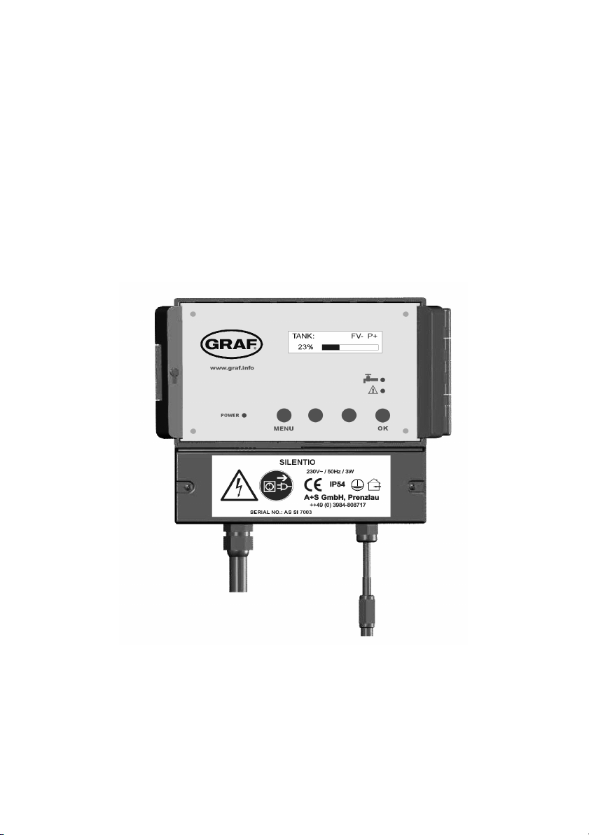
„SILENTIO“ system control
Fill level measuring device and drinking
water supply
Item no.: 351022
Otto Graf GmbH Carl-Zeiss-Str. 2-6 Tel .: 07641-5890
Kunststofferzeugnisse D-79 331 Teningen Fax: 07641-58950
Page 1
Page 2
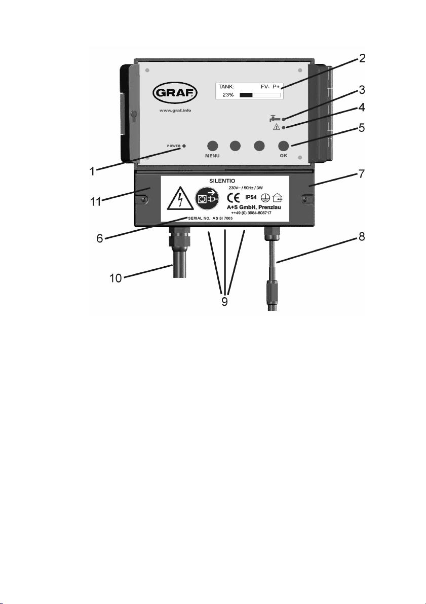
Figure 1: View of equipment
1: LED for power supply display
2: Display
3: LED for drinking water operation
4: LED for faults and malfunction
5: Operating buttons
6: Serial number
7: Lower cover of the System Control
8: Main connection cable with power coupling for data lead
9: Pre-stamped breakthrough for upgrading features
10: Mains power coupling for data lead supply cable
11: The mains circuit breaker of the system controls are under this
cover.
Page 2
Page 3
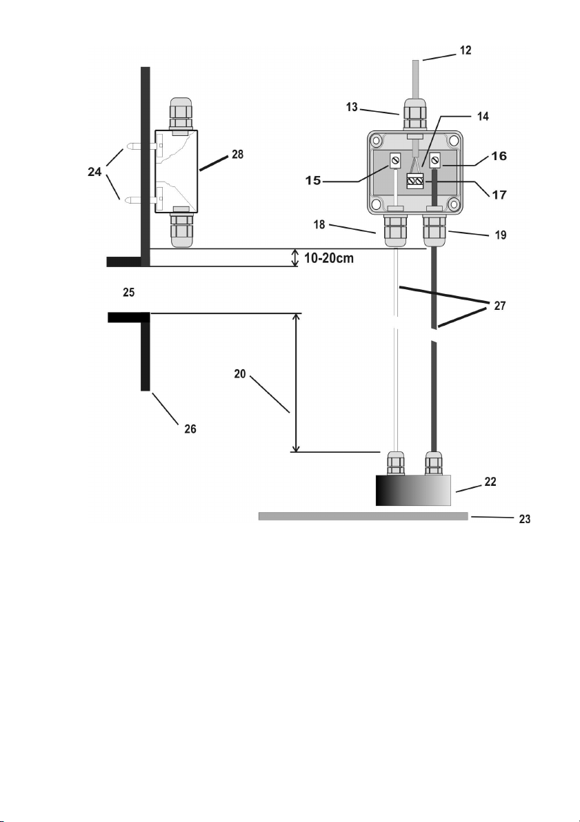
Figure 2: Sensor assembly
12: Data cable
13: screw cap 3
14: Connection of the data cable is reverse protected.
15: connect white cable here
16: connect red cable here
Page 3
Page 4
17: data cable terminal
18: screw cap 2
19: screw cap 1
20: active measuring length
22: Stainless steel probe
23: Tank floor
24: Screws must be blunted ! (danger of injury)
25: overflow
26: Tank side in dome
27: Sensor
28: Sensor control box ( measurement pick-up )
1. Safety Instructions
Please read carefully the safety and instruction manual before using this
device! Follow all instructions that are in the User Guide (Manual) to achieve
the optimal performance. Please keep these safety and operating instructions
safe for further use.
General Safety Instructions
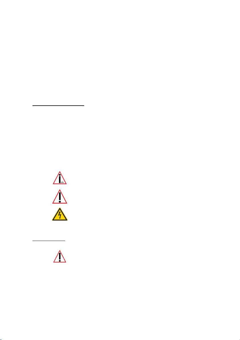
Symbol Explanation
- refers to an information
- means warning and indicates a special situation
- indicates a hazardous situation which may cause to heavy or
serious injury or even death
1.1 Personnel
The installation, commissioning and dismantling of the device
must be done only by trained and authorized personnel. During
installation, it is necessary to pay attention to the safety
regulations defined by the user and local laws and rules.
Page 4
Page 5
1.2 Proper Use of the Device
The equipment is designed exclusively for the intended purpose specified in
the manual. Any other use and / or misuse of the device can lead to unpredictable risks including death and causes the loss of all the claims against the
manufacturer.
1.3 Limitation of Liability
The manufacturer would not take over any liability for damages resulting from:
- the usage of the device by untrained and unauthorized personnel,
- use of device for not intended purpose
- opening and/or manipulation of the device
- not following the manual and safety instructions
1.4 Electric Current
!!Danger of life from electric current!!
Direct contact to the parts of the device will cause an electric shock. In
case of damage to the insulation, the device must be switched off
immediately and the damaged area must be de-energized.
While maintaining on the device, ensure that the power supply is off at
all times and make sure the device is de-energized.
1.5 Electric Shock
If objects (e.g. hairpins, needles or coins) or liquids fall into the device,
it can cause life threatening electrical short-circuits, which can lead to
fire. The user has to make sure that above mentioned objects, especially
made of metal and/ or liquid things, will not fall in to the device
intentionally or unintentionally.
1.6 Safety Operations
The operation and use of the device is to be done by instructed and
authorized personnel only.
Page 5
Page 6
1.7 Power Supply
The equipment exclusively operates with the operating voltage indicated in the
manual.
1.8 Cable Connection
When installing the cable connections, the user needs to pay attention to
the safety regulations. Always pay attention to the connection to the
protective earth ground! Pay attention when connecting with other
devices, that those have to be of the same earth potential (same heavy
current/voltage side).
1.9 Ventilation
The equipment must be installed in so that good ventilation to the device is
ensured. Do not put any covering objects on the device, such as newspapers, books
or towels.
1.10 Water and Moisture
The device is not allowed to operate in close vicinity of electrical
conductive liquids or moist areas. It is not allowed to place any liquid
things on the device or in the nearby area of the device.
Attention: Danger of Electric Shocks!
1.11 Temperature and Heat
The operating temperature of the device is defined in the specifications. The device
must not be placed near things which produce heat such as to blowers, heaters,
furnaces or other devices.
1.12 Opening the Device
Disconnect the mains plug before opening the device!
There is a risk of electrical shock when touching the parts inside the
device. It is not permitted to make any changes in the device.
Page 6
Page 7
1.13 Cleaning
Do not use any volatile solvents such as alcohol, diluents, gasoline etc.
to clean the device. Only use a dry, clean cloth.
1.14 Unusual Smell
If any unusual smoke or smell occurs, immediately switch off of the
device and remove it from the main power supply! Contact your dealer
or the manufacturer.
1.15 Fuses
The replacement of the fuses in the device is only permitted by
trained and authorized technical staff.
The change of the fuses is only allowed when the device is switched off
and is removed from the main power supply. Otherwise there is a risk of
electric shocks. The security functions and safety values are mentioned
in the manual. The guarantee for this equipment will expire in case of
using other fuses than those specified in the manual.
1.16 Repairing
The user is not allowed to perform the maintenance work by himself, except for
those specified in the manual. All maintenance and repair work must be done by
trained and authorized technical personnel.
1.17 Important notes on safety
Special Safety Instruction
Please, read and follow safety instructions carefully before assembly or using
the device!
During installation and when working with 230 V ~ mains supply the VDE
regulations must be followed. Equipment using a 230 V ~ supply may only be
installed and commissioned by a qualified tradesman. The assembly place must
allow all possible safety precautions when laying the attached cables.
Page 7
Page 8

Power supply cables and data cables may not be damaged or squeezed for any
reasons. Plan the assembly place so that you can reach the mains plug easily and
unplug it from the electrical outlet in dangerous situations.
Choose the assembly place so that children cannot play or be near to the device and
at its connections without supervision.
Before opening the device disconnect it from the mains supply (unplug) otherwise
there is a serious danger of an electrical shock.
Fuses may only be replaced with standard-compliant parts with the same nominal
value.
All liability is excluded for damages which result from non-compliance of these
instructions or from an improper handling of the device. At chosen intervals in this
hand book we will give directions for safety precautions. These safety precautions
have been specially marked.
2. Description and intended use
The “SILENTIO” is an electronic water management control system. It has been
developed especially for rain water usage systems. It can be used with a wide
variety of tank systems. Tanks made from metal or steel reinforced cement may
only be used when the following conditions have been correctly followed.
Metal tanks lead to faulty readings. Helpful is to assemble the device so that the
sensor is as far as possible from the metal sides so for example, in the centre of a
cylindrical tank. The system controls offer an easy to use guide for the switch
programming.
Using an LCD display the fill measurement is shown in 1 % stages (in relation to
the height of the tank).The sensor operates with a 12 volt supply. All programmed
values such as the tank height are retained after disconnection of the power supply
or after a power-cut.
3. Description
Performance features:
– Fill level measurement readout in 1% steps and with
an additional bar type indicator
– In 1% steps freely variable choice of the switching
points for the drinking water refill
– Automatic flushing of the system (choice of intervals
in day and time are possible)
– Dialogue oriented user guidance (choice of language)
– Equipment indication using 3 additional LED
– Supervision of the measurement pick-up and the
sensor
– Error indications in plain text
Page 8
Page 9
Technical data:
Control electronics Measurement sensors
Operating current :230VAC Measurement voltage :12DC
Fused :T50mA Measuring frequency :(0,2-20)kHz
Power consumption :3VA Data cable length :20m
Tank height :3m (optional 6m)
Measurements [mm] :155x165x90 Measurements [mm] :90x80x50
Additional pumps connection Filter cleaning valve connection
Operating voltage :230V AC Operating voltage :230V AC
Pump capacity :max. 850VA Valve effective performance : max. 1A
Notes:
Only the control electronics in the device are protected by the fuse. Valves
and pump connections are not protected. These are protected only by the
mains supply via the mains fuse.
The yellow LED indicating “Drinking water operation” is lit as soon as the
valve switches over to the mains supply. The user is made aware that the
system now uses water from the mains supply. The red LED for “Faults
and malfunctions” is lit as soon as the system identifies a fault. The display will
then show a warning that describes the cause of the fault in plain text.
4 . Assembly:
4.1 Control system
The electric mains supply plug acts also as the ON/OFF switch.
Before opening the equipment pull the plug out from the mains
socket!
The system control is integrated as standard in the basic „SILENTIO“ device from
the company Graf. Caution: Always remove the plug from the mains socket before
opening the lower cover [7] of the system control housing!
Page 9
Page 10

4 .2 Connection sensors and data cable:
The sensor electronics comprise of a stainless steel probe [22] with a red and a
white connecting cable [27] and the sensor measurement pick-up [28].
Figure 3: Sensor technology
1. Now the sensor measurement pick-up [28] (cover removed) should be
installed on the tank wall (preferably in the man hole shaft of the Graf
synthetic tank). The location of the mounted sensor pick-up should be
between 10 and 15 cm above the overflow [25]. The enclosed screws
should be used to secure the device. After fully tightening the screws, the
points that are showing themselves on the outside of the tank must be
blunted to avoid injury [24].
2. Measure the height from the bottom of the tank [23] to the end of the
terminals [15] and [16] on the measurement pick-up [28].
3. Shorten the connection cable to suit the measured height.
4. Connect the sensor cable to the sensor as described in the following
instructions: Remove between 5-7 mm of the insulation from both of the
cables. Next, pass the red cable through the screw mounting 1 [19] and
tighten this lightly, then connect the red cable to the terminal [16]. The
free white cable is now passed through the screw mounting 2 [18] and
tightened lightly, then connect the white cable to the terminal [15].
5. Now pass the end of the data cable that has no plug connector [12]
through the screw mounting 3 [13]. Lightly tighten the screw mounting
and connect the cable wire cores of the data cable [12] to the double
terminal [14]. The connection of the data cable is reverse polarity
protected. Attention! The screws should be tightened with care to
ensure that they are not damaged through over tightening.
6. Now recheck that all the screwed items and the sensor components have
Page 10
Page 11

been fitted correctly. Replace the cover of the measurement pick-up and
secure this with the appropriate fastening screws.
7. The installation of the data cable [12] to the system control must be
according to good professional practice to constitute a correct completion
of the sensor technology: A protective cable conduit must be used. (The
data cable is not suitable for installing directly in the earth).
The end of the data cable that is still unconnected is fitted with a plug
connector. This is to be plugged into the appropriate socket [8] of the
system control. Diagram 2 on page 3 makes clear the interrelation:
Note:
The red and the white cable going down to the probe should be straight and
smooth to be drawn taught by the weight of the stainless steel probe. The
stainless steel probe must hang just above the tank floor.
4 .3 Electrical connection of the filter flushing valve:
Before opening the equipment pull the plug out from the mains socket!
The connection of the valve for cleaning the rainwater filter is optional. If running
the system without the rainwater filter please read on from point 3 (Putting into operation).
Before connecting the Rainwater usage system, please ensure there is no over
straining or tension on any of the connections.
The plug of the system control unit must not be connected to the socket of the
electrical supply.
Pass the end of the cable from the solenoid valve for the rainwater cleaning filter
through the threaded grommet holder provided with the housing of the SILENTIO
system control. Now open the lower housing cover [7] of the system control (see
Figure 1). The openings for the threaded grommet holders are pre-stamped to ease
breaking out. Break out the opening for the threaded grommet holder with an
appropriate tool such as a small screw driver. Fit the supplied threaded grommet
holder into the opening and secure with the locking nut from the inside. Isolate the
wire cores of the cable in the proper manner. Pass the cable through the grommet
opening in the system control unit housing. Connect the protective earthing
conductor (green - yellow wire core) to a free terminal with the designation “PE /
Ground”.
Connect the neutral wire core (blue) to a free terminal with the designation “5”.
Connect the live electrical supply wire core (brown or black) to a free terminal with
Page 11
Page 12

the designation “3” (power supply to the filter flushing valve). The following figure
depicts the connections described above:
1: Pump
2: Power supply to additional pump
3: Power supply to filter flushing valve
4: Power supply to switch-over valve
5: Neutral conductor
P: 230V AC
PE / Ground : Earth
Figure 4: Electrical diagram for filter flushing valve
After connecting the wires, close the lower cover [7] of the system control housing.
4.4 Electrical connection of the additional pump:
Connection of the additional pump is optional. If running the system without the
additional pump please read from point 3 (putting into operation).
Before opening the equipment pull the plug out from the mains socket!
Page 12
Page 13

The plug of the system control unit must not be connected to the socket of the
electrical supply. An earth cable is absolutely necessary for connection of the
additional pump. We advise that this cable should be protected by a pipe running
from the holding tank to the rainwater usage system. Pass the end of the cable
through the threaded grommet holder provided with the housing to the SILENTIO
system control. Now open the lower cover of the system control housing (see
Figure 1). Remove the blind screw and replace this with the supplied threaded
grommet holder. Isolate the wire cores of the cable in the proper manner. Pass the
cable through the grommet opening in the system control unit housing. Connect the
protective earthing conductor (green - yellow wire core) on a free terminal with the
designation “PE / Ground”. Connect the neutral wire core (blue) on a free
terminal with the designation “5”.
Connect the live electrical supply wire core (brown or black) on a free terminal
with the designation “2” (power supply to the additional pump). The following
figure depicts the connections described above:
1: Pump
2: Power supply to additional pump
3: Power supply to filter flushing valve
4: Power supply to switch-over valve
5: Neutral conductor
P: 230V AC
PE / Ground : Earth
Figure 5: Connection diagram for additional pump
After connecting the wires, close the lower cover [7] of the system control housing.
Page 13
Page 14

5. Putting into operation:
Before putting into operation, please be absolutely sure that all the live wires and
electrical terminals are correctly insulated and that the protective covers are in
position throughout the system. Now open the transparent cover of the system
control. Now plug in the system to the appropriately fused socket for the system.
The system will now independently run through a systems check. For the duration
of the systems check (approximately 10 seconds) the display will read as follows.
Instead of “xx” the software position will be shown.
Figure 6: Display for the duration of the systems check
In the first line the system type will be shown and in the second line the software
position will be shown. After the correct initialisation of the system installation has
been acknowledged the LCD display will show the fill level as a percent (%).
The first running of the unit will show the fill level reference point that
is according to the standard factory setting tank height Standard
factory setting values:
- Tank height to overflow : 200cm (+/- 1cm)
- Drinking water switching point : ON at 10%
OFF at 12%
- Flushing the drinking water system : after 14 days for 30 seconds
- Cleaning the rainwater filter : after 14 days for 5 seconds
with rainwater
- Language : English
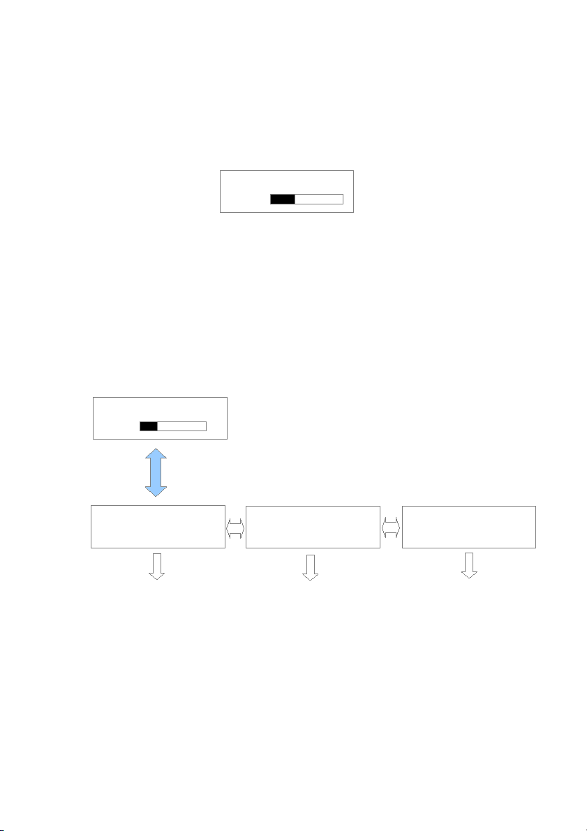
Figure 7 shows the LCD display in operation mode. Except for the fill level and the
switch positions “FV” and “P” the display should correspond with the intended
default.
Page 14
Page 15

29: Status of valve for rain water filter FV+ : Filter valve open
30: Status of house water system (Pump) FV- : Filter valve closed
31: Visual representation of fill level P+ : House water pump
running
32: Fill level % P- : No water being
with drawn
Figure 7: Display in operation
6. Set up of the system control:
After putting into operation, the system control must be adjusted and programmed
according to the conditions and requirements of the individual users system. The
required settings are easily programmed. There are four buttons for this purpose.
All necessary programming data entries follow a menu displayed by the LCD. For
the set up follow all the points listed in table 1 in the sequence as shown. Should
any error in the sequence occur then it is necessary to begin the set up again from
the beginning starting with the tank height. Begin the programming of the settings
by pressing the button marked “MENU”.
With the buttons “+” or “-” the menu may be scrolled backwards and forwards.
With the respective menu point shown the values may be altered. For this the
button “ENTER” must be used. The “?” displayed in the LCD will now change to a
“>”graphic character. With the “+” or “-” the desired value may now be entered
according to individual requirements. When the desired value has been entered this
must be confirmed by pressing the “ENTER” button. The value is only then taken
over and stored in the programming of the unit.
Page 15
Page 16
Through pressing the “MENU” button again the display changes back to the
operation mode.
It is possible to reset the unit to the factory setting standard values at any time.
The resetting can only be carried out in the operation mode (Display see Figure 6):
To do this press the “ENTER” button and hold it pressed. Now simultaneously in
addition press the “MENU” button. After a short wait the following display will be
shown:
Figure 8: Message reset to standard factory settings
As soon as this message is displayed the buttons may be released
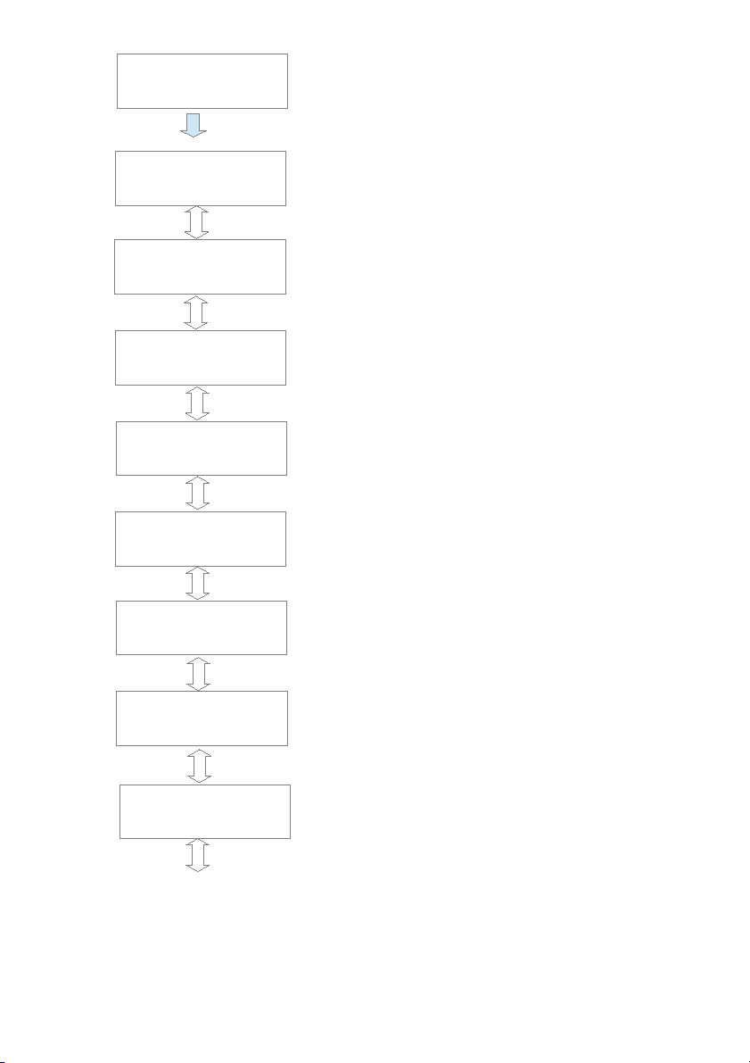
The menu structure integrated in the system control is introduced to familiarise the
user in diagram 9. To bring up the menu, press and hold the „MENU“ button for
longer than 5 seconds. All outlets are inactive when the menu level has been activated. The operation of the device is suspended. The system control switches automatically back to the operating mode when no entries have been received for approximately 30 seconds.
key „MENU“ (>5s)
+/- +/-
Depiction 9: Main menu level
Press the “ENTER” button to arrive at each of the listed sub-menu functions.
Through pressing the “MENU” button again the display changes back to the operation mode.
Page 16
DEFAULT VALUES
23%
SWITCHING POINTS
DEVICE
ADJUSTMENT
MANUAL OPERATION
TANK: FV- P+
23%
Page 17
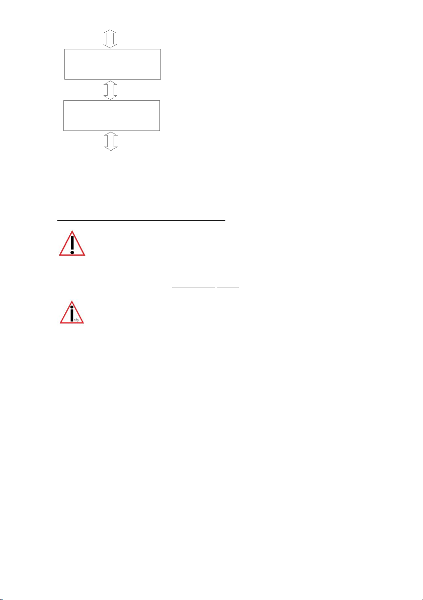
Depiction 10: Sub-menu “Switching points”
Page 17
SWITCHING POINTS
key „ENTER“
VALVE ON
0-100% 10%
VALVE OFF
0-100% 12%
Supply with mains drinking water – OFF
+ / -
Supply with mains drinking water – ON (The
numerical value is always smaller than with valve
OFF)
DW INTERVAL
0-14 DAYS 14
Flush the drinking water supply piping every 14
days. The value „0“ switches the flushing off.
+ / -
+ / -
Flushing the drinking water supply pipes for 30
seconds.
+ / -
DW DURATION
0-60 SEC 30
Cleaning the rainwater filter every 14 days
The value 0 switches the cleaning process off.
+ / -
CLEANER INTERVAL
0-14 DAYS 14
Cleaning the rainwater filter for 5 seconds
CLEANER DURATION
0-60 SEC 5
CLEANER RINSE AT
INCREMENT 2%
Cleaning the rainwater filter when the fill level
has increased by 2% after rainfall. If the fill level
continues to increase, the rinsing will be repeated
every 3 hours. The value 0 switches the cleaning
process off.
+ / -
+ / -
Main menu level
CLEANER RINSE
WITH DW NO
Permit the cleaning of the rainwater filter with
mains drinking water (standard: “NO”)
+ / -
Page 18

Press the „ENTER“ button to alter the respective switching points The value to be
altered will begin to blink. The value may then be adjusted by using the „+“ and the
„-“ buttons. Press the “ENTER” button again when the displayed value should be
accepted.
Note:
In the depiction 10 the standard factory settings have been displayed.
The following is an introduction to the general device settings:
Depiction 11: Sub-menu “General device description”
The last part of the operation level covers the manual functions:
Page 18
DEVICE
ADJUSTMENT
LANGUAGE
ENGLISH
key „ENTER“
+ / -
[20] in Figure 2
(A 6m Sensor may be ordered.)
MEASURING LENGHT
30-600cm 200
+ / -
MANUAL OPERATION
LAST FLUSH
DW 0
key „ENTER“
+ / -
HAND FLUSH
DW NO
Time scale in days; the time elapsed since the
last flush using mains drinking water
Activation of the flushing process for the mains
drinking water inlet pipe. The switch-over valve
remains permanently switched on. The yellow LED
blinks. The system is using mains drinking water !
Main menu level
Main menu level
Page 19
Depiction 12: Sub-menu “Manual functions”
7. Error messages and fault correction:
The operation of the system control is to be checked at regular intervals
(at the latest every 4 weeks).
The read out reports always represent only probabilities; e.g. no clear localization
by the device is possible for overlaying faults.
Please also take note that the system control device cannot identify any
malfunction of the house water system. (No malfunction signal is supplied
by the house water system to the system control device).
If faults are recognized by the sensors the system control cannot continue to work
independently.
The particular faults are shown on the plain text in the display:
Page 19
LAST RINSE
CLEANER 1
+ / -
HAND RINSE
CLEANER NO
Time scale in days; the time elapsed since the
last filter rinse
+ / -
+ / -
Activation of the filter rinse
Page 20
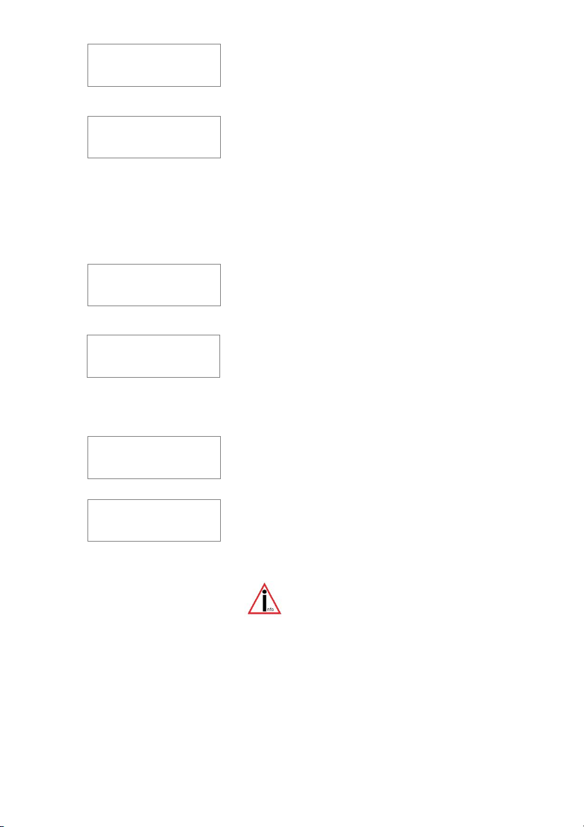
Depiction 13: Error messages
Page 20
ERROR
SENSOR
The reason for this error is that the white
sensor cable has been damaged.
ERROR
DL SHORT CIRCUIT
Error possibilities:
The data cable of the measurement pick-up
is not connected to the data cable terminal
[14] but has been connected to the sensor
terminal [15/16] -
- Cinch plug or the cinch connector has a short
circuit
- Wires of the data cable have been damaged
ERROR
SENSOR CONTROL
The measurement sensor delivers no signal
and must be replaced.
ERROR
SENSOR SYSTEM
For further diagnosis, remove the stainless steel
weight [22] out of the water. If the error indication
has now stopped, then the sensor it self was the
cause of the fault. If the error indication should
continue, this implies that the measurement pick-up
is defect.
ERROR
NO SIGNAL
The communication between the system
control to the measurement pick-up is
interrupted.
ERROR
MEMORY
First try re-setting the system control to the
factory default settings . If the error message
continues to be displayed then it is necessary
to contact your service partner.
Note: After re-setting to the factory
default settings all the newly
programmed setting values will
have been overwritten and must be
re-programmed!
Page 21

Before opening the equipment pull the plug out from the mains
socket!
If the device shows no function at all then check whether the main electrical supply
provides current and also check the house fuses.
If the electrical outlet is under current, then unplug the mains plug from the system
control. Without connection to current open the lower cover of the system control
(see Figure 1) and check the equipments mains fuse.
If your efforts are unsuccessful, please consult the manufacturer by E-Mail:
GmbH
Niederlassung Prenzlau
Franz Wienholz Str. 40
17291 Prenzlau
Tel. : +49 (3984)- 80 87 17
Fax : +49 (3984)- 80 69 61
Internet : http:// www.aktuatorikundsensorik.com/
E-Mail : info@AS-Prenzlau.de
We prefer to receive an E-Mail, if you must contact us then be sure to enter
the serial number of your controller that begins with “AS”.( The serial number
is found on the name/type label. )
8. Upgrade options:
The SILENTIO control device can also be equipped with a number of additional
special functions.
1. Optional pressure sensor
Using a pressure sensor, alternative mediums or depths
may be adapted to the use of the device. The sensor must
be matched the required specifications of the device.
2. Optional drain pump
If the fill level of the tank reaches a specified value, then
a valve or a pump can be activated. This is to prevent the
fill level of the tank from exceeding a specified
maximum level.
Page 21
Page 22

3. Optional refill
If the fill level in the main tank sinks below a specified
level, then a second tank is employed to back up and re
fill the main tank. The pump used in this process must
also be equipped with a mechanism to prevent it from
running dry.
If this system is required, then the device must be sent to the manufacturer. There
follows an additional calculation.
Note:
The standard system control device may be equipped with a maximum of
one additional switch output point.
9 . General installation and assembly regulations:
It is necessary to these instructions when installing a rain water usage equipment:
EN 806:
- Drinking water installation
- Planning and implementation
- Calculation of the pipe diameters
- Using the equipment
EN 1717:
- free outlet between drinking and rainwater
- Notification sign to inform that a rainwater usage system is installed
in the locality
- Notification signs marking the rainwater outlets
- Notification signs marking the rainwater installations network
- Backflow prevention (e.g. a non-return/check valve)
- Frost free installation
- Reservoir/tank with air bleeding/ventilation
Page 22
Page 23
- No diameter reduction in the drainage system according to EN 1256
- Technical regulations in relation to groundwater drainage according
to EN 752
- Drainage systems outside of buildings according to the regulations of
the local services authorities
- When required: Obligatory registration of the system and other mandatory stipulations
10. Disposal of the equipment:
11. Analogue outlet:
Your device has been fitted with an additional analogue port. This port shows the
percent values from the system control (0% – 100%) by a voltage range from 0V to
10V. The following connection values apply:
Minimal apparent ohmic resistance : 20K Ohm
Short circuit protection : Yes
Short circuit current : Approx 15mA
Cable length : maximum 200m
(shielded)
Note:
The system control is only capable of displaying whole percent values (no
fractions). These are shown on the analogue signal display. A maximum of
one digit behind the point is to be considered for the evaluation of the
pro-cent value.
Page 23
Old equipment may not be disposed of in
the house refuse. It must be brought to the
recognised professional recycling depot.
Please help – ensure your old electronics
come to a separate recycling.
Page 24
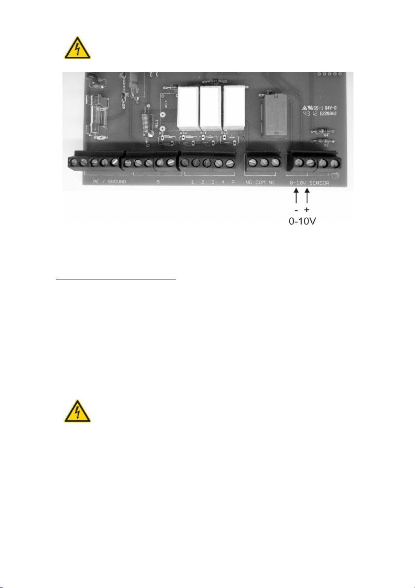
Before opening the equipment pull the plug out from the mains
socket!
Depiction 14: Location of the analogue port
12. Alarm indicator contact:
As an additional function, your unit is equipted with a potential-free alarm indicator
contact. This contact is designed as a changeover contact element. A maximum of
230V AC is approved when a current of 1A is switched. The activation of this contact occurs as soon as one of the malfunctions listed under Point 6 appears. The
picture on the following page shows the location of the connections. These become
available as soon as the lower cover of the system control unit is opened (see [7] in
diagram 1).
Before opening this cover, it is important to disconnect the device from the
mains electricity supply!
Before opening the equipment pull the plug out from the mains
socket!
Explanation of terms:
- COM is the common port
- NC is coupled to the COM port when there is no current.
- NO is connected to the COM port when there is a malfunction
Page 24
Page 25
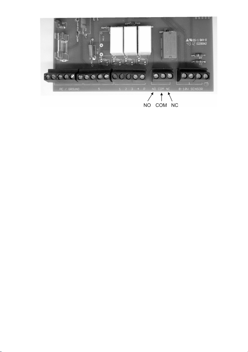
Depiction 15: Location of the fault indicator
The M 12/M16 opening on the underside of the system control device must be
opened and the cable drawn through. Place the supplied grommet into the opening
and pass the cable through into the system control.
Page 25
Page 26

Attachment A – Symbols used:
Attention! Pull out the mains plug from the socket before
opening the device.
Warning of dangerous electrical voltage
Attention! An error has occurred.
Mains drinking water operation
Page down
Page up
Protection classification I
Only for use in a dry areas.
Page 26
Page 27

Room for your notes:
Page 27
Page 28

Revision history:
Revision Date Description Author
Silentio 3.4 12.02.18 Formatting SU
Room for your notes:
Purchase date : ...................................
Device serial number / Type : AS SI .......................
Active measuring length : ...................................
Software level SILENTIO REV : .......
Design and specifications are subject to change without notice
Dated: February 2018 ; Version: SI 3.4
man_Silentio_3-4_eng.odt
Page 28
 Loading...