

Graf SICKER-TUNNEL TWIN Series, SICKER-TUNNEL 300 L, SICKER-TUNNEL Series, SICKER-TUNNEL TWIN 600 L Installation And Maintenance Instructions Manual
Page 1
SICKER-TUNNEL / TWIN
DE
Anleitung für Einbau und Wartung
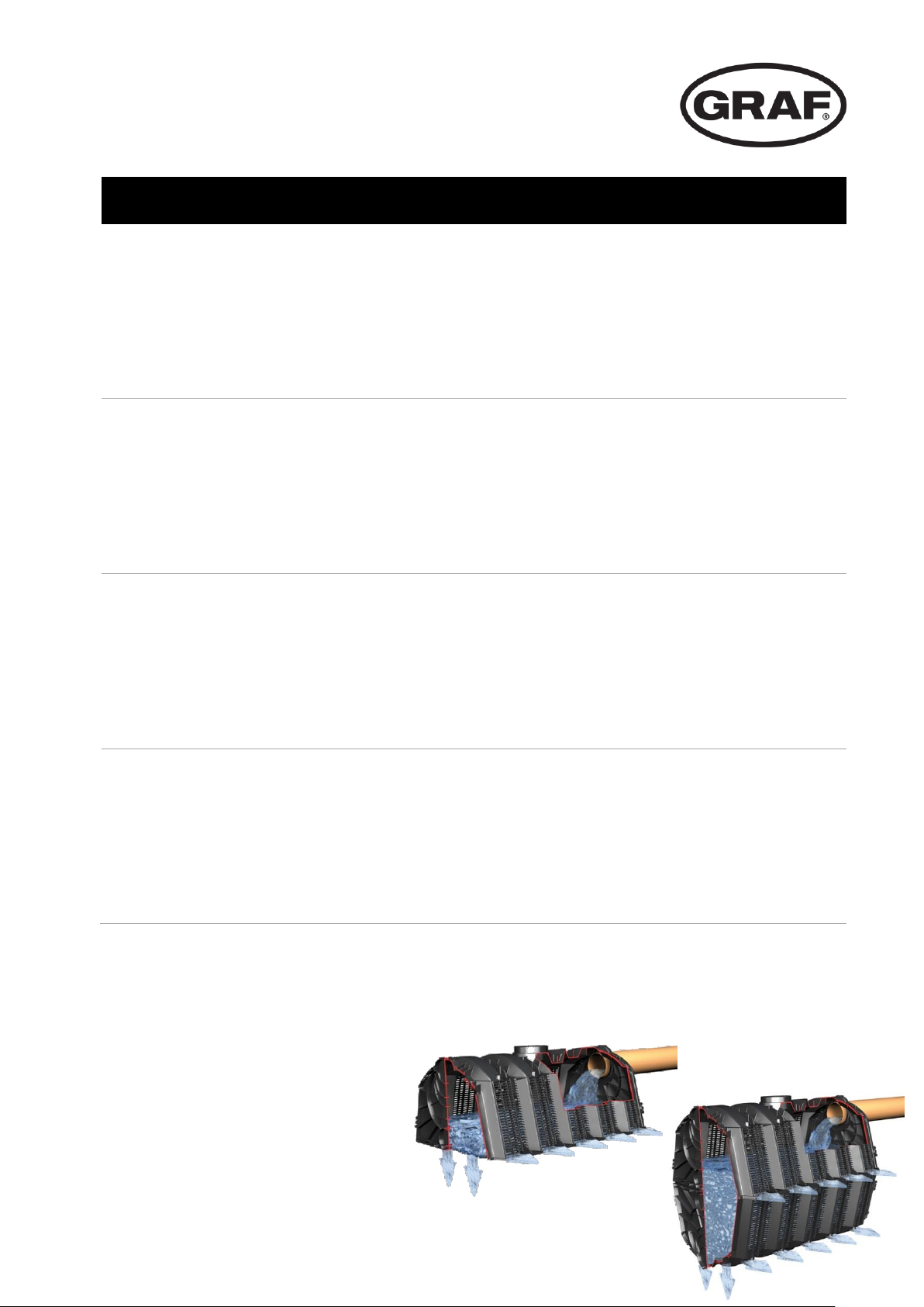
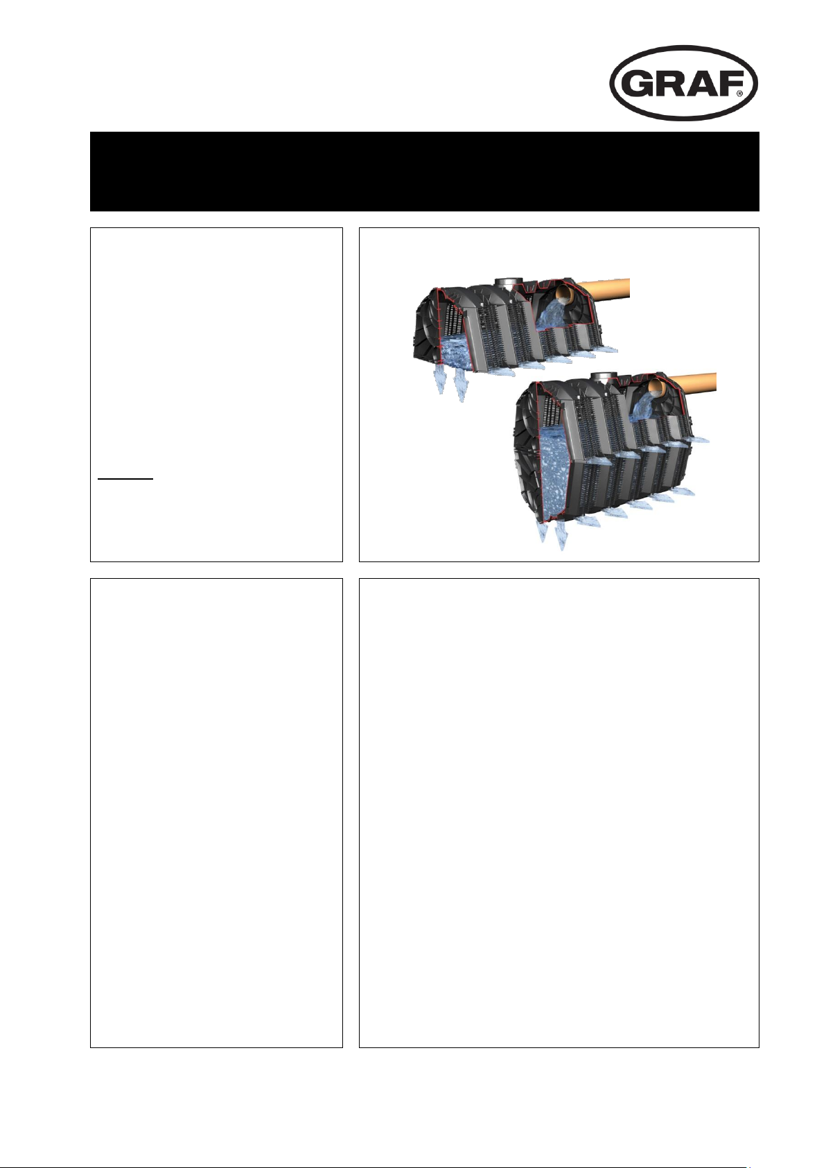
GRAF Sicker-Tunnel / Sicker-Tunnel twin
>> Seite 1-6
EN
Installation and maintenance instructions for
GRAF Infiltration tunnel / Infiltration tunnel twin
>> Page 7-12
ES
Instrucciones de instalación y mantenimiento
Túnel de infiltración / Túnel de infiltratión twin
>> Página 13-18
FR
Notice d’Installation Tunnel d’épandage GRAF + Tunnel Twin
>> Page 19-25
Page 2

Otto Graf GmbH
Kunststofferzeugnisse
Carl-Zeiss-Str. 2-6
DE-79331 Teningen
Tel.: +49 7641 589-66
Fax: +49 7641 589-50
mail@graf.info
www.graf-online.de
Page 3
Anleitung für Einbau und Wartung
GRAF Sicker-Tunnel/ Sicker-Tunnel twin
SICKER-TUNNEL 300 L,
schwarz, LKW-befahrbar
Best.-Nr. 230010
SICKER-TUNNEL TWIN 600 L,
schwarz, PKW-befahrbar
Best.-Nr. 410130
SICKER-TUNNEL
Endplatte 300 L
Best.-Nr. 231004
Zubehör:
Verbindungselemente (6 Stck)
Best.-Nr. 410094
Geotextil (lfm, Rollenbr. 5 m)
Best.-Nr. 231002
Die in dieser Anleitung
beschriebenen Punkte sind
unbedingt zu beachten. Bei
Nichtbeachtung erlischt jeglicher
Garantieanspruch. Für alle über
GRAF bezogenen Zusatzartikel
erhalten Sie separate in der
Transportverpackung beiliegende
Einbauanleitungen.
Eine Überprüfung der Bauteile auf
eventuelle Beschädigungen hat
unbedingt vor dem Versetzen in
die Baugrube zu erfolgen.
Fehlende Anleitungen können Sie
unter www.graf.info downloaden
oder bei GRAF anfordern.
Inhaltsübersicht
1. ALLGEMEINE HINWEISE 2
1.1 Sicherheit 2
2. TECHNISCHE DATEN 3
3. EINBAUBEDINGUNGEN 3
3.1 Standortwahl 3
3.2 Abmessungen der Baugrube 4
4. EINBAU 5
4.1 Anschluss der Zu- und Entlüftungsleitungen 5
4.2 Einbau des Sicker-Tunnel / Twin 5
mail@graf.info
www.graf.info
1 / 25
Page 4

1. Allgemeine Hinweise
mail@graf.info
www.graf.info
1.1 Sicherheit
Bei sämtlichen Arbeiten sind die einschlägigen Unfallverhütungsvorschriften nach BGV C22 zu beachten.
Des Weiteren sind bei Einbau, Montage, Wartung, Reparatur usw. die in Frage kommenden Vorschriften
und Normen zu berücksichtigen.
Vor dem Einbau sind die Rigolenelemente auf Beschädigungen zu überprüfen. Beschädigte oder
fehlerhafte Tunnel dürfen nicht eingebaut werden!
Die Firma GARANTIA bietet ein umfangreiches Sortiment an Zubehörteilen, die alle aufeinander
abgestimmt sind und zu kompletten Systemen ausgebaut werden können. Die Verwendung anderer
Zubehörteile kann dazu führen, dass die Funktionsfähigkeit der Anlage beeinträchtigt und die Haftung für
daraus entstandene Schäden aufgehoben wird.
Bitte beachten:
Bei Nässe und Frost besteht erhöhte Rutschgefahr beim Betreten der Rigolenelemente.
2 / 25
Page 5
2. Technische Daten
3. Einbaubedingungen
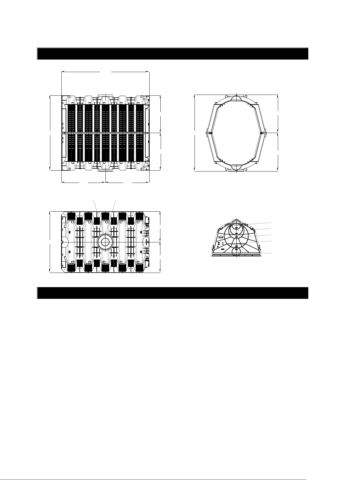
510
1160
1020
580580
490
490
980
incl. Endplatte 1220 mm
510
510
1160
400
1020
800
580580
490
490
980
DN 100
DN 150
DN 200
DN 300
DN 100
DN 100
DN 200
incl. Endplatte 1220 mm
400
510
mail@graf.info
www.graf.info
3.1 Standortwahl
Abstand zum Keller > 6 m
Abstand zum Grundwasser mindestens 1 m
Der Abstand zum bestehenden oder geplanten Baumbestand muss mindestens dem zu
erwartenden Kronendurchmesser entsprechen.
3 / 25
Page 6

3. Einbaubedingungen
Verkehrsbelastung
Sicker-Tunnel
Sicker-Tunnel Twin
Kurzfristig
max. 100 kN/m²
max. 75 kN/m²
Langfristig
max. 59 kN/m²
max. 35 kN/m²
ohne Verkehrsbelastung
min. Erdüberdeckung
250 mm
250 mm
max. Erdüberdeckung*
3740 mm
1480 mm
max. Einbautiefe*
4250 mm
2500 mm
PKW-befahrbar
min. Erdüberdeckung
250 mm
500 mm
max. Erdüberdeckung*
3490 mm
1480 mm
max. Einbautiefe*
4000 mm
2500 mm
LKW 12
min. Erdüberdeckung
max. Erdüberdeckung*
max. Einbautiefe*
500 mm
3240 mm
3750 mm
-
SLW 30
min. Erdüberdeckung
max. Erdüberdeckung*
max. Einbautiefe*
500 mm
2740 mm
3250 mm
-
SLW 40
min. Erdüberdeckung
max. Erdüberdeckung*
max. Einbautiefe*
500 mm
2490 mm
3000 mm
-
SLW 60
min. Erdüberdeckung
max. Erdüberdeckung*
max. Einbautiefe*
750 mm
1740 mm
2250 mm
-
Technische Daten
Sicker-Tunnel
Sicker-Tunnel Twin
Volumen 300 L
600L
Gewicht 11 kg
22 kg
Material
100 % Polypropylen (PP)°
100 % Polypropylen (PP)°
Abmessungen
Länge exkl. Endplatten
1160 mm
1160 mm
Länge inkl. Endplatten
1200 mm
1200 mm
Breite
800 mm
800 mm
Höhe
510 mm
1020 mm
mail@graf.info
www.graf.info
3.2 Abmessungen der Baugrube
Die Abmessung der Grube richtet sich nach der Anzahl der zu verlegenden Sickertunnel in Längs- und in
Querrichtung.
Die nachfolgende Tabelle gibt die Erdüberdeckung und die maximale Einbautiefe bis Unterkante der
Rigole an:
*Die max. Einbautiefe* bzw. Erdüberdeckung* bezieht sich auf Erdmaterial mit einem inneren
Reibungswinkel von ϱ = 40,0°
°Die Material- bzw. Rohstoffangabe kann unter Umständen Recyclingmaterial enthalten.
4 / 25
Page 7
4. Einbau
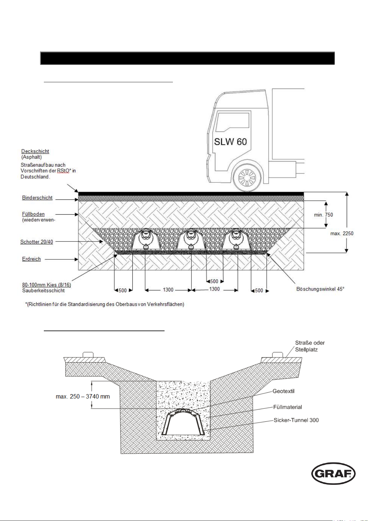
Auf die waagerecht abgezogene Grundfläche der Baugrube wird eine ca. 80 mm starke
Sauberkeitsschicht aus Kies (Körnung 8/16) aufgetragen. Auf dieses Kiesbett werden die Sicker-Tunnel /
Twin aufgesetzt und miteinander in Längsrichtung verbunden. Zum Schutz der Sicker-Tunnel werden
diese mit Geotextil abgedeckt. Das Geotextil sollte an den Stößen mind. 300-500 mm überlappen.
Es ist auf eine eng anliegende und gleichmäßige Verfüllung zu
achten. Es dürfen keine Lücken oder Toträume entstehen. Die
erste Lage besteht aus Schotter 20/40 und dient zur
vollständigen Überdeckung der Tunneloberkante. Danach kann
zur Verfüllung der Bauaushub als Füllmaterial verwendet
werden. Anschließend wird die Grube lagenweise und
gleichmäßig verfüllt.
Die Geländeoberfläche und der Geländeunterbau muss
entsprechend der zu erwartenden Belastung vorbereitet
werden. Wird über dem Sicker-Tunnel / Twin Rasen
angepflanzt, sollte die Anlage mit einer wasserundurchlässigen
Folie oder einer ca. 100 mm starken Lehmschicht abgedeckt
werden, da der Rasen ansonsten schneller austrocknen kann
als die restliche Rasenfläche
Das Geogitter wird als zusätzliche Lastverteilung unter
befahrenen Flächen verwendet.
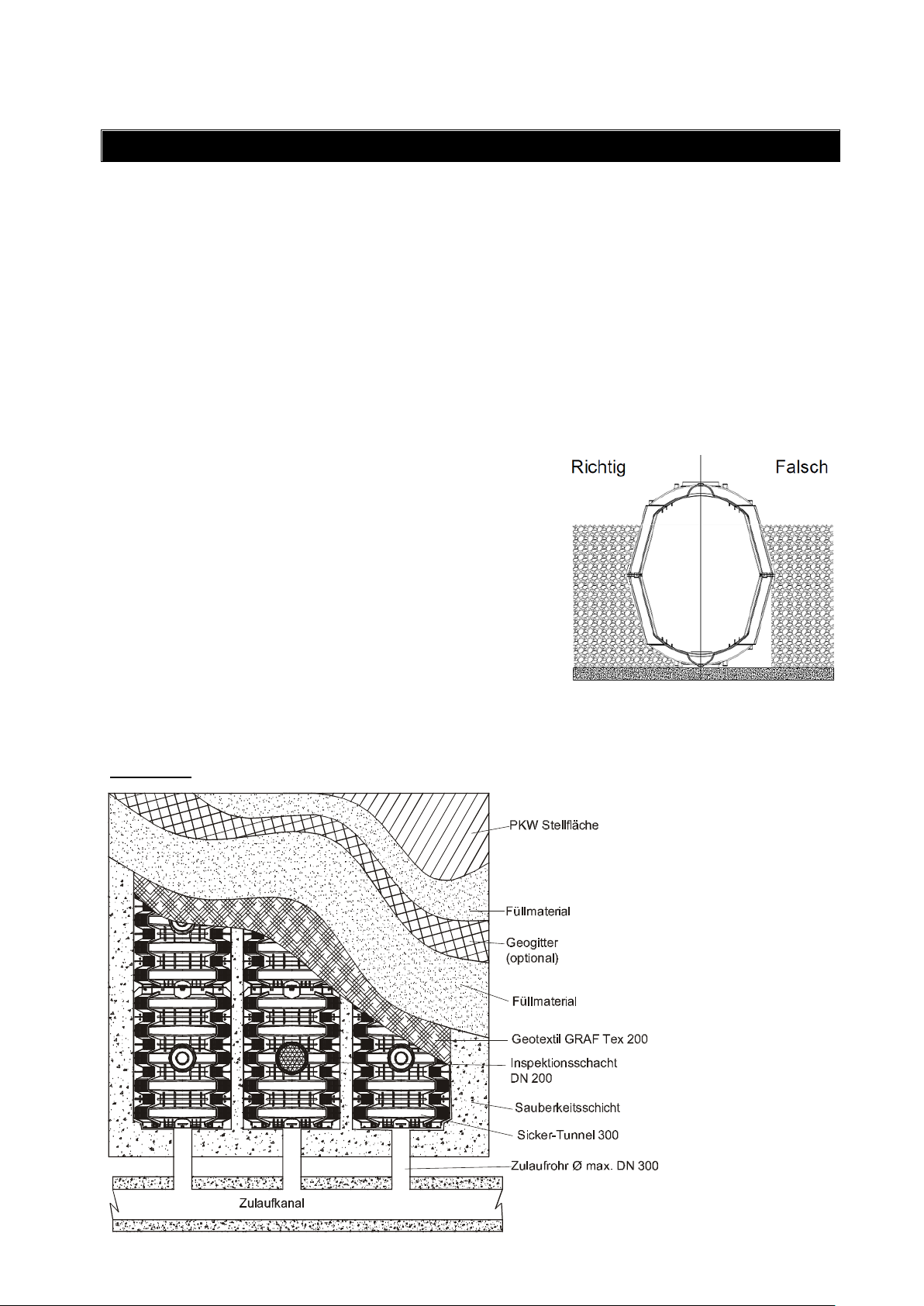
Draufsicht:
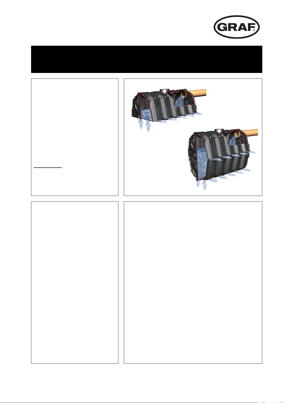
Verfüllung beim Sicker-Tunnel Twin
mail@graf.info
www.graf.info
4.1 Anschluss der Zu- und Entlüftungsleitungen
Die Zuleitungen werden an den Stirnseiten an den Endplatten angeschlossen. Dazu werden die
entsprechend perforierten und beschrifteten Kreisausschnitte herausgetrennt. Die Leitungen müssen ca.
15 cm in die Module hineinragen. Um einen gleichmäßigen Wassereintritt zu gewährleisten ist bei einer
flächenhaften Verlegung der Module eine Verteilung der Zuleitungen auf jeden Versickerungsstrang
erforderlich. Der Inspektions-/ Entlüftungsabschluss wird oben an dem dafür vorgesehenen
Anschlussstutzen angeschlossen. Je Strang ist mindestens eine Entlüftung einzuplanen.
4.2 Einbau des Sicker-Tunnel / Twin
5 / 25
Page 8
Otto Graf GmbH – Carl-Zeiss-Str. 2-6 – DE-79331 Teningen – Tel.: +49 7641 589-0 – Fax: +49 7641 589-50
GRAF Distribution S.A.R.L – 45, route d´Ernolsheim – FR-67120 Dachstein Gare – Tél.:+33 388 49-7310 – Fax: +33 388 49-3280
GRAF Iberica Tecnología del Plástico S.L. – Marquès Caldes de Montbui, 114 – ES-17003 Girona – Tel.: +34 972 913767 – Fax: +34 972 913766
GRAF UK Ltd – Target House – Thorpe Way Ind. Estate – Banbury – Oxfordshire – UK-OX16 4SP – Tel.: +44 1608 661-500 – Fax: + 44 1295 211333
2015-07
4. Einbau
Schnittdarstellung – SLW 60 Belastungsfall:
mail@graf.info
www.graf.info
Schnittdarstellung offene Mulden-Rigole:
6 / 25
Page 9
Installation and maintenance instructions
GRAF Infiltration tunnel / Infiltration tunnel Twin
Infiltration tunnel 300 L,
black, lorry loading
Order No. 230010
Infiltration tunnel Twin 600 L,
black, vehicle loading
Order No. 410130
End plate for
Infiltration Tunnel /Twin
Order No. 231004
Accessories:
Connecting elements (6 Units)
Order No. 410094
Geotextile (per m., roll width 5 m)
Order No. 231002
The points described in these
instructions must be observed
under all circumstances. All
warranty rights are invalidated in
the event of non-observance.
Separate installation instructions
are enclosed in the transportation
packaging for all additional articles
purchased from GRAF.
Missing instructions must be
requested from us immediately.
The components must be checked
for any damage prior to insertion
into the trench under all
circumstances.
Missing instructions can be
downloaded on www.graf.info.
Table of contents
GENERAL NOTES 8
1.
1.1 Security 8
TECHNICAL DATA 8
2.
INSTALLATION CONDITIONS 9
3.
3.1 Choice of location 9
3.2 Excavation dimensions 9
INSTALLATION 11
4.
4.1 Connecting the inlet and venting pipes 11
4.2 Installation of the Infiltration Tunnel / Twin 11
mail@graf.info
www.graf.info
7 / 25
Page 10

General notes
1.
Technical data
2.
510
1160
1020
580580
490
490
980
incl. Endplatte 1220 mm
510
510
1160
400
1020
800
580580
490
490
980
DN 100
DN 150
DN 200
DN 300
DN 100
DN 100
DN 200
incl. Endplatte 1220 mm
400
510
mail@graf.info
www.graf.info
1.1 Security
The relevant accident prevention regulations according to BGV C22 must be observed during all work.
The relevant regulations and standards must additionally be taken into consideration during installation,
assembly, servicing, repair, etc.
Before installation, the EcoBloc Inspect and ground plates should be checked for damage.
Damaged or defective blocks must not be installed!
GRAF offers an extensive range of accessories, all of which are designed to match each other and which
can be extended to form complete systems. The use of other accessories may lead to impediments to the
system's functional capability, therefore invalidating liability for resulting damage.
Please note:
There is an increased risk of slipping on Infiltration tunnel system in frosty and wet conditions.
8 / 25
Page 11

Installation conditions
3.
Transportation loads
Infiltration Tunnel
Infiltration Tunnel Twin
Short-term
max. 100 kN/m²
max. 75 kN/m²
Long-term
max. 59 kN/m²
max. 35 kN/m²
Without traffic loads
min. Earth covering
250 mm
250 mm
max. Earth covering*
3740 mm
1480 mm
max. Installation depth*
4250 mm
2500 mm
Vehicle loading
min. Earth covering
250 mm
500 mm
max. Earth covering*
3490 mm
1480 mm
max. Installation depth*
4000 mm
2500 mm
lorry 12
min. Earth covering
max. Earth covering*
max. Installation depth*
500 mm
3240 mm
3750 mm
-
HGV 30
min. Earth covering
max. Earth covering*
max. Installation depth*
500 mm
2740 mm
3250 mm
-
HGV 40
min. Earth covering
max. Earth covering*
max. Installation depth*
500 mm
2490 mm
3000 mm
-
HGV 60
min. Earth covering
max. Earth covering*
max. Installation depth*
750 mm
1740 mm
2250 mm
-
Incl. endplates 1220 mm
mail@graf.info
www.graf.info
3.1 Choice of location
Distance from basement > 6 m
Distance from ground water minimum > 1 m
The distance from the existing or planned trees must be at least the expected spread of the trees
crown.
3.2 Excavation dimensions
The measurements of the excavation is in accordance with the number of drainage blocks to be installed
by multiplying the length and width dimensions.
The following table gives the required earth covering and the maximum installation depth to the lower
edge of the blind drain:
*The maximum installation depth* or earth covering* is related to the ground substance with an inside
angle of friction from ϕ = 40,0°.
°The material or raw material specification possibly contains recycled material.
9 / 25
Page 12

3. Installation conditions
Technical data
Infiltration Tunnel
Infiltration Tunnel Twin
Volume
Litre
300 L
600 L
Weight 11 kg
22 kg
Material
100 % polypropylene (PP)°
100 % polypropylene (PP)°
Measurements
Length excl. Endplatten
1160 mm
1160 mm
Length incl. Endplatten
1200 mm
1200 mm
Width
800 mm
800 mm
Height
510 mm
1020 mm
mail@graf.info
www.graf.info
10 / 25
Page 13

Installation
4.
The horizontal, flat footprint of the excavation first has to be filled with a layer of grit (approx. 80 mm, grain
size 8/16) which serves as granular sub-grade course. The Infiltration Tunnel / Twin are put on the gravel
pit and connected with each other in lines (lengthwise). The percolation tunnel is covered with a geotextile
fabric for protection. The filter fleece should overlap the end of the modules by at least 300-500 mm.
Ensure the tunnel connections have a uniform & tight fitting, with no
gaps or dead spots. The first layer is gravel 20/40 and will be used
to cover the Tunnel top edge completely. The material dug out
during construction can then be used as filler. Afterwards the
excavation will be filled steadily and in layers. The terrain of the
ground surface and substructure should be the expected load to be
prepared. If a lawn is planted on top of the percolation surface, the
system should be covered with a waterproof film or a clay layer of
approx. 100 mm, as otherwise the lawn above the percolation
system may faster dry up than the rest of the lawn.
The rotting-resistant ground fence can be used as additional load
distribution under trafficable areas.
Plan view:
Sicker-Tunnel Twin
mail@graf.info
www.graf.info
4.1 Connecting the inlet and venting pipes
The feed pipes will be connected at the front of the end plates. For this purpose the accordingly
perforated and labelled circular cut-outs will be detached. The feed pipes must extend into the tunnel
modules approximately 15 cm. For assuring that the water enters into the modules in a steady way, it is
essential for extensive module laying that every percolation line is equipped with its own feeding pipe.
Use the connection on the upper side of the module for the deaeration / inspection end (min.1 deaeration
/ inspection end per line).
4.2 Installation of the Infiltration Tunnel / Twin
11 / 25
Page 14

Otto Graf GmbH – Carl-Zeiss-Str. 2-6 – DE-79331 Teningen – Tel.: +49 7641 589-0 – Fax: +49 7641 589-50
GRAF UK Ltd – Target House – Thorpe Way Ind. Estate – Banbury – Oxfordshire – UK-OX16 4SP – Tel.: +44 1608 661-500 – Fax: +44 1295 211333
2015-07
4. Installation
soil
filling
material
80-100 mm grit (8/16)
granular subbase
surface layer
Additionaly required
black top finish to
national standards
e.g. United Kingdom 250 mm
black top layer
road/
parking space
GRAF-Tex geotextile
filling material
infiltration Tunnel
girder
max. 250 – 3740 mm
gravel 20/40
angle of slope 45°
Drawing – lorry – loading 60 to:
mail@graf.info
www.graf.info
Section open swale infiltration ditch:
GRAF Distribution S.A.R.L – 45, route d´Ernolsheim – FR-67120 Dachstein Gare – Tél.:+33 388 49-7310 – Fax: +33 388 49-3280
GRAF Iberica Tecnología del Plástico S.L. – Marquès Caldes de Montbui, 114 – ES-17003 Girona – Tel.: +34 972 913767 – Fax: +34 972 913766
12 / 25
Page 15

Instrucciones de instalación y mantenimiento
Túnel de infiltración / Túnel de infiltración Twin
TÚNEL DE INFILTRACIÓN 300 L,
negro, transitable para camiones
Código 230010
TÚNEL DE INFILTRACIÓN TWIN
600 L, negro, transitable para
automóviles
Código 410130
TÚNEL DE INFILTRACIÓN
Placa final 300 L
Código 231004
Accesorios:
Elementos de unión (6 unidades)
Código 410094
Geotextil (m.l., ancho bobina 5
m)
Código 231002
Los puntos descritos en estas
instrucciones deben ser
respetados obligatoriamente. Si no
se observan las instrucciones
prescribe todo derecho de
garantía. Recibirá adjuntas en el
embalaje de transporte por
separado las instrucciones de
montaje para todos los artículos
adicionales adquiridos a GRAF.
Antes de trasladar los
componentes a la excavación
examínelos sin falta para detectar
eventuales desperfectos.
Si faltaran instrucciones, puede
descargarlas desde www.graf.info
o solicitarlas a GRAF.
Índice de contenido
1. INDICACIONES GENERALES FEHLER! TEXTMARKE NICHT DEFINIERT.
1.1 Sicherheit Fehler! Textmarke nicht definiert.
2. DATOS TECNICOS FEHLER! TEXTMARKE NICHT DEFINIERT.
3. CONDITIONES PARA LA INSTALACION FEHLER! TEXTMARKE NICHT DEFINIERT.
3.1 Elección de la ubicación Fehler! Textmarke nicht definiert.
3.2 Dimensiones de la excavación Fehler! Textmarke nicht definiert.
4. INSTALACION FEHLER! TEXTMARKE NICHT DEFINIERT.
4.1 Conexión de los tubos de entrada y de aireación Fehler! Textmarke nicht definiert.
4.2 Instalación del túnel de infiltración / Twin Fehler! Textmarke nicht definiert.
mail@graf.info
www.graf.info
13 / 25
Page 16

1. Indicaciones generales
mail@graf.info
www.graf.info
1.1 Sicherheit
En la ejecución de todos los trabajos deben seguirse las prescripciones pertinentes de prevención de
accidentes según BGV C22.
Aparte de esto se deben seguir las prescripciones y normas correspondientes para la ejecución de los
trabajos de instalación, montaje, mantenimiento, reparación, etc.
Antes del montaje hay que examinar los elementos de los bloques de infiltración para detectar
eventuales daños. ¡No instalar túneles dañados o defectuosos!
GARANTIA ofrece un amplio surtido de accesorios que han sido adaptados entre sí y que pueden
ampliarse para formar sistemas completos. La utilización de otros accesorios puede provocar la pérdida
de funcionalidad de la instalación, de modo que el fabricante no asume ninguna responsabilidad sobre
los daños generados en estos casos.
Observe por favor:
Con tiempo húmedo o tras una helada aumenta el riesgo de resbalar al pisar sobre los túneles de
infiltración.
14 / 25
Page 17

2. Datos técnicos
3. Conditiones para la instalación
510
1160
1020
580580
490
490
980
incl. Endplatte 1220 mm
510
510
1160
400
1020
800
580580
490
490
980
DN 100
DN 150
DN 200
DN 300
DN 100
DN 100
DN 200
incl. Endplatte 1220 mm
400
510
Incl. placa final 1220 mm
mail@graf.info
www.graf.info
3.1 Elección de la ubicación
Distancia respecto a edificios > 6 m
Distancia a las aguas subterráneas: mínimo 1 m
La distancia a los árboles ya plantados o previstos para ser plantados debe equivaler, como
mínimo, al diámetro que se espera alcanzará la corona de estos árboles.
15 / 25
Page 18

3. Conditiones para la instalación
Datos técnicos
Túnel de infiltración
Túnel de infiltración Twin
Volumen 300 l
600 l
Peso
11 kg
22 kg
Material
100 % polipropileno (PP)°
100 % polipropileno (PP)°
Dimensiones
Longitud excluyendo las
placas finales
1160 mm
1160 mm
Longitud incluyendo las
placas finales
1200 mm
1200 mm
Anchura
800 mm
800 mm
Altura
510 mm
1020 mm
Carga accidental por tráfico
Túnel de infiltración
Túnel de infiltración Twin
De corta duración
máximo 100 kN/m²
máximo 75 kN/m²
De larga duración
máximo 59 kN/m²
máximo 35 kN/m²
sin carga
accidental por
tráfico
Cob. mínima con tierra
250 mm
250 mm
Cob. máxima con tierra*
3740 mm
1480 mm
Prof. montaje máxima*
4250 mm
2500 mm
Transitable por
turismos
Cob. mínima con tierra
250 mm
500 mm
Cob. máxima con tierra*
3490 mm
1480 mm
Prof. montaje máxima*
4000 mm
2500 mm
Camiones de hasta
12t
Cob. mínima con tierra
Cob. máxima con tierra*
Prof. montaje máxima*
500 mm
3240 mm
3750 mm
-
Camiones de hasta
30t
Cob. mínima con tierra
Cob. máxima con tierra*
Prof. montaje máxima*
500 mm
2740 mm
3250 mm
-
Camiones de hasta
40t
Cob. mínima con tierra
Cob. máxima con tierra*
Prof. montaje máxima*
500 mm
2490 mm
3000 mm
-
Camiones de hasta
60t
Cob. mínima con tierra
Cob. máxima con tierra*
Prof. montaje máxima*
750 mm
1740 mm
2250 mm
-
mail@graf.info
www.graf.info
3.2 Dimensiones de la excavación
Las dimensiones de la excavación se orientarán en la cantidad de túneles de infiltración a instalar en
sentido longitudinal y transversal.
La tabla siguiente indica la capa de cobertura con tierra y la profundidad máxima de instalación hasta el
canto inferior del módulo de infiltración:
*La profundidad máxima de montaje* o cobertura con tierra* se refiere a tierra con un ángulo de
rozamiento interno ϱ = 40,0°.
°El material o la materia prima indicada puede contener eventualmente material reciclado.
16 / 25
Page 19

4. Instalación
Rellenar el fondo de la zanja con una capa de grava (tamaño 8/16) de aprox. 80 mm de grosor. Sobre
esta capa de grava se colocan los túneles de infiltración / Twin y se unen entre sí en sentido longitudinal.
Proteger los túneles de infiltración cubriéndolos con un geotextil. El geotextil debe solaparse, como
mínimo, 300-500 mm en las uniones.
El relleno deberá quedar bien ajustado al túnel y ser uniforme.
No deberán quedar zonas sin compactar ni espacios vacíos.
La primera capa, compuesta por grava 20/40, tiene la finalidad
de asentar el túnel. Después se puede rellenar con el material
excavado. Rellenar a continuación la zanja por capas de
espesor uniforme.
Preparar la superficie y la infraestructura del terreno de
acuerdo con las cargas previstas. Si se prevé plantar césped
sobre el túnel de infiltración / Twin habrá que cubrir la
instalación con una lámina impermeable o una capa de arcilla
de aproximadamente 100 mm de espesor, ya que, de lo
contrario, el césped situado sobre el túnel podría secarse más
rápidamente que el resto de la superficie de césped.
Debajo de las superficies transitadas por vehículos hay que
utilizar la geomalla para mejorar el reparto de las cargas.
Vista superior:
Rellendado en caso del túnel de infiltración Twin
Correcto
Incorrecto
mail@graf.info
www.graf.info
4.1 Conexión de los tubos de entrada y de aireación
Los tubos de entrada se conectan en las placas finales. Con este fin hay que cortar las piezas circulares
pre-perforadas y rotuladas. Los tubos tienen que entrar aprox. 15 cm dentro de los módulos. En el caso
de una instalación de varias filas de túneles habrá que prever tubos de entrada a cada fila de túneles de
infiltración, con el fin de asegurar un aporte de agua uniforme. Conectar la tapa de registro / salida de
aireación arriba, en la boca prevista para este fin. Hay que prever, como mínimo, una aireación por
tramo.
4.2 Instalación del túnel de infiltración / Twin
17 / 25
Page 20

Otto Graf GmbH – Carl-Zeiss-Str. 2-6 – DE-79331 Teningen – Tel.: +49 7641 589-0 – Fax: +49 7641 589-50
GRAF Distribution S.A.R.L – 45, route d´Ernolsheim – FR-67120 Dachstein Gare – Tél.:+33 388 49-7310 – Fax: +33 388 49-3280
GRAF Iberica Tecnología del Plástico S.L. – Marquès Caldes de Montbui, 114 – ES-17003 Girona – Tel.: +34 972 913767 – Fax: +34 972 913766
GRAF UK Ltd – Target House – Thorpe Way Ind. Estate – Banbury – Oxfordshire – UK-OX16 4SP – Tel.: +44 1608 661-500 – Fax: + 44 1295 211333
2016-02
4. Instalación
mail@graf.info
www.graf.info
Vista en sección – Supuesto de carga "Camiones de hasta 60t":
18 / 25
Page 21

Otto Graf GmbH – Carl-Zeiss-Str. 2-6 – DE-79331 Teningen – Tel.: +49 7641 589-0 – Fax: +49 7641 589-50
GRAF Distribution S.A.R.L – 45, route d´Ernolsheim – FR-67120 Dachstein Gare – Tél.:+33 388 49-7310 – Fax: +33 388 49-3280
GRAF Iberica Tecnología del Plástico S.L. – Marquès Caldes de Montbui, 114 – ES-17003 Girona – Tel.: +34 972 913767 – Fax: +34 972 913766
GRAF UK Ltd – Target House – Thorpe Way Ind. Estate – Banbury – Oxfordshire – UK-OX16 4SP – Tel.: +44 1608 661-500 – Fax: + 44 1295 211333
2016-02
Français
Notice d’installation
Tunnel d’épandage GRAF + Tunnel Twin
Tunnel d’épandage Graf 300 L –
passage ≤ 3,5 T Réf: 410090
Tunnel Twin
600 L – passage ≤ 3,5 T Réf:
410130
Paroi d’entrée/sortie (1 pc.) pour
Tunnel (2) / Twin (4)
Réf: 410091
Set de clips (6 pc.) pour Tunnel
Twin Réf: 410094
Geotextile Graf 200 g/m² (Au
mètre - largeur 5m) Réf : 369014
Afin de garantir le bon fonctionnement et la longévité de votre
installation, les différents points
décrits dans cette notice doivent
scrupuleusement être respectés.
Tout manquement à ces règles
annulera systématiquement la
garantie. Lisez également toutes les
notices des autres éléments fournis
par la société GRAF. Vous
trouverez les notices de montage
jointes dans l’emballage.
Toute notice manquante doit nous
être réclamée sans dé- lai.
Avant la mise en œuvre du produit
dans la fouille, il est important de
vérifier que
celui-ci n’a pas été endommagé.
L’installation doit être effectuée par
un installateur professionnel.
Sommaire
1. INDICATIONS GENERALES 21
1.1 Sécurité 21
2. DONNEES TECHNIQUES 21
3. CONDITIONS D'INSTALLATION 22
3.1 Conditions d'installation 22
3.2 Dimensions de la fouille pour tunnels 23
3.3 Dimensions de la fouille pour tunnels Twin 24
4. INSTALLATION 24
4.1 Raccordement dey tuyaux d'arrivée et d'évent 24
4.2 Installation du Tunnel/ Tunnel Twin 24
mail@graf.info
www.graf.info
19 / 25
Page 22

Otto Graf GmbH – Carl-Zeiss-Str. 2-6 – DE-79331 Teningen – Tel.: +49 7641 589-0 – Fax: +49 7641 589-50
GRAF Distribution S.A.R.L – 45, route d´Ernolsheim – FR-67120 Dachstein Gare – Tél.:+33 388 49-7310 – Fax: +33 388 49-3280
GRAF Iberica Tecnología del Plástico S.L. – Marquès Caldes de Montbui, 114 – ES-17003 Girona – Tel.: +34 972 913767 – Fax: +34 972 913766
GRAF UK Ltd – Target House – Thorpe Way Ind. Estate – Banbury – Oxfordshire – UK-OX16 4SP – Tel.: +44 1608 661-500 – Fax: + 44 1295 211333
2016-02
1. Indications générales
2. Données techniques
510
1160
1020
580580
490
490
980
incl. Endplatte 1220 mm
510
510
1160
400
1020
800
580580
490
490
980
DN 100
DN 150
DN 200
DN 300
DN 100
DN 100
DN 200
incl. Endplatte 1220 mm
400
510
Avec paroi d’entrée/ sortie
1220 mm
mail@graf.info
www.graf.info
1.1 Sécurité
Lire attentivement la notice d’installation et d’utilisation avant la pose et la conserver pour toute utili-
sation ultérieure.
Les règles de sécurité, les instructions d’installation, de montage, d’entretien ou de réparation doi-
vent être scrupuleusement respectées.
L’installation, le montage, l’entretien et la réparation des matériels concernés qui doivent être réalisés conformément aux normes et prescriptions en vigueur..
N’utiliser que des accessoire de marque GRAF. L’utilisation d’autres accessoires pourrait ne pas
être adaptée et engendrer des problèmes tels que fuites.
20 / 25
Page 23

Otto Graf GmbH – Carl-Zeiss-Str. 2-6 – DE-79331 Teningen – Tel.: +49 7641 589-0 – Fax: +49 7641 589-50
GRAF Distribution S.A.R.L – 45, route d´Ernolsheim – FR-67120 Dachstein Gare – Tél.:+33 388 49-7310 – Fax: +33 388 49-3280
GRAF Iberica Tecnología del Plástico S.L. – Marquès Caldes de Montbui, 114 – ES-17003 Girona – Tel.: +34 972 913767 – Fax: +34 972 913766
GRAF UK Ltd – Target House – Thorpe Way Ind. Estate – Banbury – Oxfordshire – UK-OX16 4SP – Tel.: +44 1608 661-500 – Fax: + 44 1295 211333
2016-02
Données techniques
Tunnel
Tunnel Twin
Litres
300 L
600 L
Longueur hors paroi d’entrée/sortie
1160 mm
1160 mm
Longueur avec paroi d’entrée/sortie
1200 mm
1200 mm
Largeur
800 mm,
800 mm
Hauteur
510 mm
1020 mm
Poids
11 kg
22 kg
Matériau
100 % polypropylène (PP)
100 % polypropylène (PP)
3. Conditions d’installation
mail@graf.info
www.graf.info
3.1 Conditions d’installation :
Distance minimale d’une habitation : 5 m
(Cette distance peut être adaptée en fonction du contexte local)
Distance de la nappe phréatique : mini. 1 m
Dans le cas d’une installation à proximité d’un arbre existant ou en prévision, la
distance entre le Tunnel et le tronc de l’arbre doit correspondre au minimum au
diamètre de la couronne de l’arbre adulte.
Pour éviter le co lmatage du tunnel, il est indispensable d’installer un filtre avant l’entrée
des EP, en amont de l’ouvrage.
21 / 25
Page 24

Otto Graf GmbH – Carl-Zeiss-Str. 2-6 – DE-79331 Teningen – Tel.: +49 7641 589-0 – Fax: +49 7641 589-50
GRAF Distribution S.A.R.L – 45, route d´Ernolsheim – FR-67120 Dachstein Gare – Tél.:+33 388 49-7310 – Fax: +33 388 49-3280
GRAF Iberica Tecnología del Plástico S.L. – Marquès Caldes de Montbui, 114 – ES-17003 Girona – Tel.: +34 972 913767 – Fax: +34 972 913766
GRAF UK Ltd – Target House – Thorpe Way Ind. Estate – Banbury – Oxfordshire – UK-OX16 4SP – Tel.: +44 1608 661-500 – Fax: + 44 1295 211333
2016-02
Passage
Piétons
VL
(Max.2.5 T)
PL (Max.12
TT)
SPL
(Max.30 T)
SPL
(Max.40 T)
SPL
(Max.60 T)
Hauteur de remblai minimale
Avec un angle de frottement interne
φ´=25°
0,25m
0.50m
Non
Non
Non
No
Hauteur de remblai minimale
Avec un angle de frottement interne
φ´=30°
0,25m
0.25m
0.75m
1.00m
1.25m
No
Hauteur de remblai minimale
Avec un angle de frottement interne
φ´=35°
0,25m
0.25m
0.50m
0.50m
0,75m
0.75m
Hauteur de remblai minimale
Avec un angle de frottement interne
φ´=40°
0,25m
0.25m
0.50m
0.50m
0.50m
0.75m
Profondeur maximum d'installation
Avec un angle de frottement interne
φ´=20°
1.75m
Non
Non
Non
Non
No
Profondeur maximum d'installation
Avec un angle de frottement interne
φ´=25°
2.25m
2.00m
Non
Non
Non
No
Profondeur maximum d'installation
Avec un angle de frottement interne
φ´=30°
3.00m
2.75m
2.50m
2.00m
1.75m
No
Profondeur maximum d'installation
Avec un angle de frottement interne
φ´=35°
3.75m
3.50m
3.25m
2.75m
2.50m
1.75m
Profondeur maximum d'installation
Avec un angle de frottement interne
φ´=40°
4.25m
4.00m
3.75m
3.25m
3.00m
2.25m
mail@graf.info
www.graf.info
3.2 Dimensions de la fouille pour tunnels
Le tableau ci-dessous donne la hauteur de recouvrement ainsi que la profondeur
d’enfouissement maximale, en fonction de la nature du terrain.
φ´ = angle de frottement interne = densité du sol en place
un angle de frottement interne
φ´=25°
Sable fin un angle de
frottement interne
φ´=30° Sable
gros/moyen un angle de frottement
interne
φ´=40° Gravier
Il faut respecter une distance minimale de 0,50m entre chaque rangée de tunnels.
22 / 25
Page 25

mail@graf.info
Otto Graf GmbH – Carl-Zeiss-Str. 2-6 – DE-79331 Teningen – Tel.: +49 7641 589-0 – Fax: +49 7641 589-50
GRAF Distribution S.A.R.L – 45, route d´Ernolsheim – FR-67120 Dachstein Gare – Tél.:+33 388 49-7310 – Fax: +33 388 49-3280
GRAF Iberica Tecnología del Plástico S.L. – Marquès Caldes de Montbui, 114 – ES-17003 Girona – Tel.: +34 972 913767 – Fax: +34 972 913766
GRAF UK Ltd – Target House – Thorpe Way Ind. Estate – Banbury – Oxfordshire – UK-OX16 4SP – Tel.: +44 1608 661-500 – Fax: + 44 1295 211333
2016-02
Charges admises
Tunnel Twin
A court terme
Long terme
max. 7,5 t/m²
max. 3,5 t/m²
Sans passage
véhicules
Recouvrement min.
Recouvrement max.
Profondeur
d’enfouissement max.
250 mm
1480 mm
2500 mm
Passage véhicules
jusqu’à 3,5T
Recouvrement min.
Recouvrement max.
Profondeur
d’enfouissement max.
500 mm
1480 mm
2500 mm
4 Installation
tunnels / tunnels Twin, sur ce lit de pose et les jumeler dans le sens de la longueur. Pour les tunnels
Twin, utiliser les 6 clips fournis pour assembler les deux coques. Recouvrir les tunnels avec du
géotextile 200g/m2 pour les pro- téger et les isoler du matériau de remblai. Le géotextile devrait
dépasser de 30 à 50 cm sur tous les côtés du tunnel. Remblayer ensuite la fouille de façon
homogène sur toute sa longueur. La surface du terrain doit être préparée de manière à pouvoir
accueillir la charge prévue. Dans le cas où du gazon doit être planté au- dessus des tunnels,
l’installation devrait être recouverte d’une géomembrane ou d’une co uche de terre très argileuse
d’au moins 100 mm d’épaisseur, dans le cas contraire, le gazon planté au-dessus des tunnels pour-
rait jaunir plus vite que le reste de la pelouse.
exemple.
www.graf.info
3.3 Dimensions de la fouille pour tunnels Twin
4.1 Raccordement des tuyaux d’arrivée et d’évent
Les tuyaux d’entrée sont raccordés au niveau des parois d’entrée. Pour cela, percer au niveau des
emplace- ments prévus. Les tuyaux doivent pénétrer d’au moins 20 cm dans les tunnels.
Pour permettre une répartition homogène de l’eau dans les tunnels, il est nécessaire de réaliser un
canal de distribution et d’entrer dans chaque rangée de tunnels (voir schéma ci-dessous). Le
raccordement de l’évent se fait en haut de tunnel au niveau de l’emplacement prévu. Prévoir au
minimum un évent par rangée de tunnels (DN 110 ou DN 200).
4.2 Installation du Tunnel / Tunnel Twin
23 / 25
Page 26

Otto Graf GmbH – Carl-Zeiss-Str. 2-6 – DE-79331 Teningen – Tel.: +49 7641 589-0 – Fax: +49 7641 589-50
GRAF Distribution S.A.R.L – 45, route d´Ernolsheim – FR-67120 Dachstein Gare – Tél.:+33 388 49-7310 – Fax: +33 388 49-3280
GRAF Iberica Tecnología del Plástico S.L. – Marquès Caldes de Montbui, 114 – ES-17003 Girona – Tel.: +34 972 913767 – Fax: +34 972 913766
GRAF UK Ltd – Target House – Thorpe Way Ind. Estate – Banbury – Oxfordshire – UK-OX16 4SP – Tel.: +44 1608 661-500 – Fax: + 44 1295 211333
2016-02
Vue du dessus :
Canal de distribution
mail@graf.info
www.graf.info
Chaussée
Remblai
Géo-grille (facultatif)
Remblai : mélange de terre végétale et de
sable
Géotextile 200g/m2
Regard d’inspection DN 110 / DN 200
Gravier (8/16)
Tunnel d’épandage 300 L
Tuyau d’arrivée Ø max. DN 300
24 / 25
Page 27

Otto Graf GmbH – Carl-Zeiss-Str. 2-6 – DE-79331 Teningen – Tel.: +49 7641 589-0 – Fax: +49 7641 589-50
GRAF Distribution S.A.R.L – 45, route d´Ernolsheim – FR-67120 Dachstein Gare – Tél.:+33 388 49-7310 – Fax: +33 388 49-3280
GRAF Iberica Tecnología del Plástico S.L. – Marquès Caldes de Montbui, 114 – ES-17003 Girona – Tel.: +34 972 913767 – Fax: +34 972 913766
GRAF UK Ltd – Target House – Thorpe Way Ind. Estate – Banbury – Oxfordshire – UK-OX16 4SP – Tel.: +44 1608 661-500 – Fax: + 44 1295 211333
2016-02
Geogrille (facultatif)
Remblai
Regard
dd’inspection/ évent
Geotextile
Min. 500 mm
Tunnel
Coupe d’une tranchée d’infiltration
250-3740 mm max.
Hauteur de remblai
Géotextile
Remblai
Tunnel
Schéma de principe
mail@graf.info
www.graf.info
25 / 25
 Loading...