

Page 1
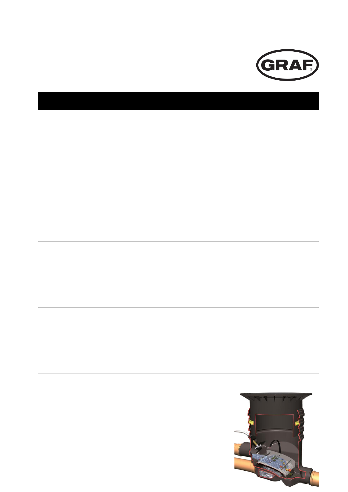
OPTIMAX-GEWERBEFILTER
DE
Anleitung für Einbau und Wartung GRAF Optimax®Gewerbe-Filter Extern
>> Seite 1-20
EN
Installation instructions and maintenance for the GRAF
Optimax®-Industrial-Filter external
>> Page 6-20
FR
Notice d’installation et d’entretien pour filter bâtiment
GRAF Optimax® externe
>> Page 11-20
ES
Instrucciones de instalación y mantenimiento
GRAF Optimax®-Filtro Externo
>> Página 16-20
Page 2

Otto Graf GmbH
Kunststofferzeugnisse
Carl-Zeiss-Str. 2-6
D-79331 Teningen
Tel.: +49 7641 589-66
Fax: +49 7641 589-50
mail@graf.info
www.graf-online.de
Page 3

Optimax®-Gewerbe-Filter
Extern für den Grünbereich
(begehbar)
Art.-Nr. 340035
Optimax®-Gewerbe-Filter
Extern für PKW befahrene
Flächen
Art.-Nr. 340036
Die in dieser Anleitung beschriebenen Punkte sind unbedingt zu beachten. Bei Nichtbeachtung erlischt jeglicher Garantieanspruch. Für alle über
GRAF bezogenen Zusatzartikel
erhalten Sie separate in der
Transportverpackung beiliegende Einbauanleitungen.
Fehlende Anleitungen sind umgehend bei uns anzu-fordern.
Eine Überprüfung der Be-hälter
auf eventuelle Be-schädigungen
hat unbedingt vor dem Versetzen in die Baugrube zu erfolgen.
Der Einbau ist von einer Fachfirma durchzuführen.
Seite 1 von 20
Anleitung für Einbau und Wartung GRAF Optimax®-
Gewerbe-Filter Extern
Inbetriebnahme
Wartung
Inhaltsübersicht
1. Allgemeine Hinweise Seite 2
1.1 Sicherheit
1.2 Kennzeichnungspflicht
2. Einbaubedingungen Seite 2
2.1 Optimax®-Gewerbe begehbar
2.2 Optimax®-Gewerbe PKW befahrbar
3. Transport und Lagerung Seite 3
3.1 Transport
3.2 Lagerung
4. Technische Daten Seite 3
5. Einbau / Montage externe Filter Seite 4
5.1 Vorbereitung Baugrube
5.2 Einsetzen und Anschlüsse legen
5.3 Teleskop montieren
5.4 Verfüllen Seite 5
5.5 Montage Aushebevorrichtung Seite 5
6. Inbetriebnahme und Wartung Seite 5
6.1 Inbetriebnahme
6.2 Wartung
Page 4

1. Allgemeine Hinweise
2. Einbaubedingungen
Seite 2 von 20
1.1 Sicherheit
Bei sämtlichen Arbeiten sind die einschlägigen Unfallverhütungsvorschriften nach BGV C22
zu beachten. Besonders bei Begehung der Behälter ist eine 2. Person zur Absicherung erforderlich.
Desweiteren sind bei Einbau, Montage, Wartung, Reparatur usw. die in Frage kommenden
Vorschriften und Normen zu berücksichtigen. Hinweise hierzu finden Sie in den dazugehörigen Abschnitten dieser Anleitung.
Die Installation der Anlage bzw. einzelner Anlagenteile muß von qualifizierten Fachleuten
durchgeführt werden.
Bei sämtlichen Arbeiten an der Anlage bzw. Anlageteilen ist immer die Gesamtanlage außer
Betrieb zu setzen und gegen unbefugtes Wiedereinschalten zu sichern.
Der Deckel ist stets, außer bei notwendigen Arbeiten am Filter, verschlossen zu halten, ansonsten besteht höchste Unfallgefahr. Der Sitz des Deckels ist regelmäßig zu kontrollieren.
Die Firma GRAF bietet ein umfangreiches Sortiment an Zubehörteilen, die alle aufeinander
abgestimmt sind und zu kompletten Systemen ausgebaut werden können. Die Verwendung
anderer Zubehörteile kann dazu führen, dass die Funktionsfähigkeit der Anlage beeinträchtigt und die Haftung für daraus entstandene Schäden aufgehoben wird.
1.2 Kennzeichnungspflicht
Alle Leitungen und Entnahmestellen von Brauchwasser sind mit den Worten „Kein Trink-
wasser“ schriftlich oder bildlich zu kennzeichnen (DIN 1988 Teil 2, Abs. 3.3.2.) um auch
nach Jahren eine irrtümliche Verbindung mit dem Trinkwassernetz zu vermeiden. Auch bei
korrekter Kennzeichnung kann es noch zu Verwechslungen kommen, z.B. durch Kinder.
Deshalb müssen alle Brauchwasser – Zapfstellen mit Ventilen mit Kindersicherung installiert werden.
2.1 Optimax®-Gewerbe-Filter Extern begehbar
- Der Filter mit Teleskop grün und PE – Deckel grün darf nur in nicht befahrenem Grünbe-
reich installiert werden.
- Die kurzfristige Belastung der begehbaren PE – Abdeckungen beträgt max. 150 kg, die
langfristige Flächenbelastung max. 50 kg.
- Die maximale Einbautiefe bis Filtersohle beträgt 1320 mm
- Anschließbare Dachfläche bei Anschluss an DN 150 = 750 m², bei DN 200 = 1500 m²
2.2 Optimax®-Gewerbe-Filter Extern PKW befahrbar
- Durch die Verwendung des Teleskopaufsatzes (anthrazit) und der Gussabdeckung Klas-
se B nach DIN EN 124 kann der Filter unter PKW befahrenen Flächen installiert werden.
Der Filter darf auf keinen Fall unter LKW befahrenen Flächen eingebaut werden. (siehe
Punkt 5.3.2)
- Die Erdüberdeckung über dem Zulaufrohr beträgt mind. 450 mm, die max. Einbautiefe
bis Filtersohle beträgt 1320 mm.
- Anschließbare Dachfläche bei Anschluss an DN 150 = 750 m², bei DN 200 = 1500 m²
Page 5
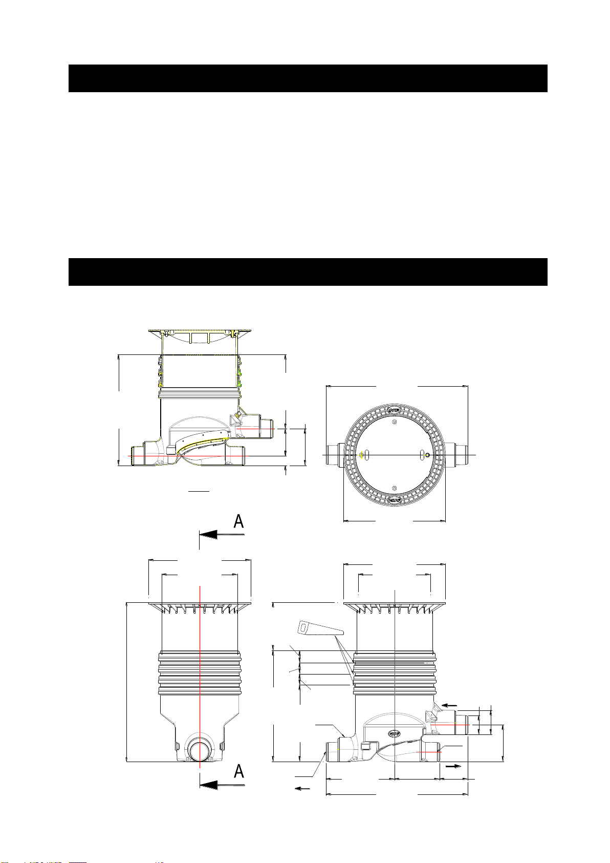
Ø600 [23,6]
1180 [46,5]
92 [3,6]
Ta nk
92 [3,6]
235 [9,3]
79 [3,1]
633 [24,9]
Ø630 [24,8]
DN160
400 [15,7]
DN160
920 [36,2]
Abla uf
A-A
850 [33,5]
303 [11,9]
1180 [46,5]
Ø850 [33,5]
617 [24,3]
920 [36,2]
DN200
224 [8,8]
103 [4,0]
Stufenlose Einbautiefe von 733 -1320 m m
steplessly variable installation depth of 733-1320 mm
Zu la uf
570 [22,4]
DN 200
DN 160
303 [11,9]
375 [14,8]
Ø850 [33,5]
3. Transport und Lagerung
4. Technische Daten
Seite 3 von 20
3.1 Transport
Während des Transportes sind die Filter gegen Verrutschen und Herunterfallen zu sichern.
Werden die Filter zum Transport mit Spanngurten gesichert, ist zu gewährleisten, dass der
Filter unbeschädigt bleibt.
Beanspruchungen durch Stöße sind unbedingt zu vermeiden. Auf keinen Fall dürfen die
Filter über den Untergrund gerollt oder geschleift werden.
3.2 Lagerung
Eine notwendige Zwischenlagerung der Filter muss auf einem geeigneten, ebenen Untergrund erfolgen. Während der Lagerung muss eine Beschädigung durch Umwelteinflüsse
oder Fremdeinwirkung vermieden werden.
Page 6
5. Einbau / Montage externe Filter
Seite 4 von 20
5.1 Vorbereitung Baugrube
Damit ausreichend Arbeitsraum vorhanden ist und der Filter gleichmäßig verdichtet werden
kann, muss die Grundfläche der Baugrube die Filtermaße auf jeder Seite um 50 cm überragen. Die Böschung ist nach DIN 4124 anzulegen. Der Baugrund muss waagerecht und eben
sein. Die Tiefe der Grube muss so bemessen sein, dass die Einbautiefe bis Filtersohle maximal 1320 mm beträgt. Als Unterbau wird eine Schicht verdichteter Rundkornkies, (Körnung
8/16 nach DIN 4226 – 1) Dicke ca. 10 cm aufgetragen.
Wichtig: Die Standfläche für den Filter muss absolut waagerecht sein, um eine optimale
Funktion zu gewährleisten.
5.2 Einsetzen und Anschlüsse legen
Der Filter wird in die vorbereitete Grube eingesetzt und mit den entsprechenden Leitungen
verbunden. Es ist darauf zu achten, daß alle Leitungen mit einem Gefälle in Fliesrichtung von
mind. 1% ohne Durchbiegungen verlegt werden. Um die Fließgeschwindigkeit des zufließenden Wassers zu reduzieren sollte das Zulaufrohr vor dem Filter in einem „U“, ähnlich einem
Siphon verlegt werden, dies hat den Effekt, dass die Wasserausbeute wesentlich verbessert
wird.
Wichtig: DIN 1986 ist unbedingt zu beachten, d.h. Zulauf = Ablauf.
5.3 Teleskop montieren
5.3.1 Teleskop begehbar
Das Teleskop wird von oben in das Filtergehäuse eingeschoben. Bei Grubentiefen < 900 mm
muss das Teleskop und ggf. das Filtergehäuse
gekürzt werden. Es ist unbedingt darauf zu achten, dass die Zuleitung im endgültig eingebauten
Zustand nicht vom Teleskop ganz oder teilweise
verschlossen wird. Vor dem Einschieben wird
die Profildichtung in die Dichtnut des Gehäuses
eingesetzt. Das Teleskop, sowie die Dichtung
müssen mit der mitgelieferten Schmierseife (keine Schmierstoffe auf Mineralölbasis verwenden) großzügig eingerieben werden. Achtung: Trocknet die Schmierseife an läßt sich das
Teleskop nur noch sehr schwer bewegen und es besteht die Gefahr, dass die Dichtung aus
der Dichtnut rutscht. Vor dem Verfüllen muss die Dichtung auf ihren korrekten Sitz überprüft
werden. Das Teleskop muss ausreichend unterfüttert werden, so dass sich Kräfte auf keinen
Fall auf das Gehäuse übertragen können.
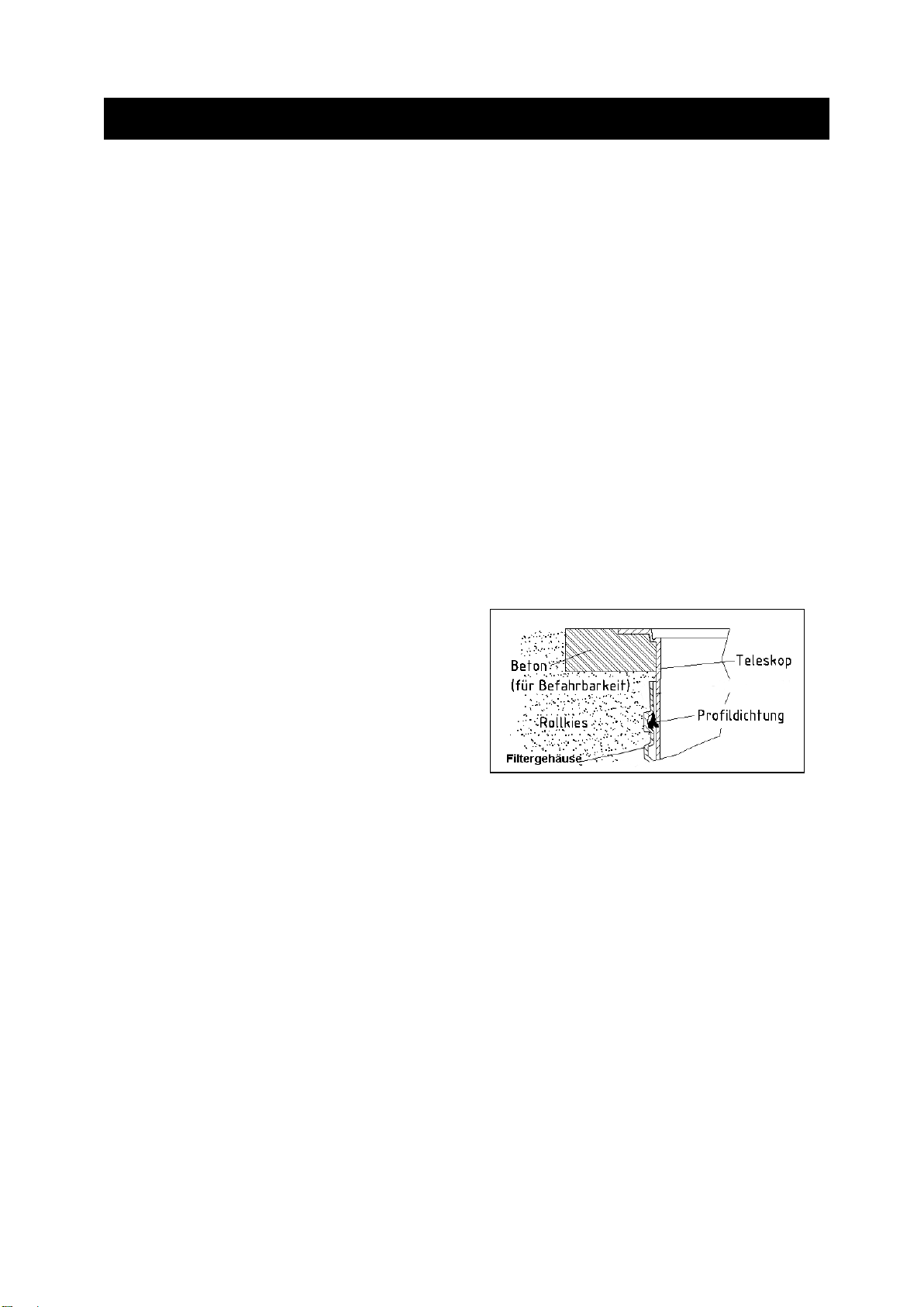
5.3.2 Teleskop PKW befahrbar
Das Teleskop wie in Punkt 5.3.1 montieren. Um die PKW - Befahrbarkeit zu gewährleisten
muss unter dem Teleskopkragen mit Magerbeton unterfüttert werden. Die anzufüllende Betonschicht muss mind. 20 cm breit und ca. 30 cm dick sein. Achtung: Unbedingt die Stahl –
Gussabdeckung verwenden. Verkehrslasten von LKW sind nicht zulässig. Das Teleskop
muß ausreichend unterfüttert werden, so dass sich Kräfte auf keinen Fall auf das Gehäuse
übertragen können.
Page 7

5. Einbau / Montage externe Filter
6. Inbetriebnahme und Wartung
Seite 5 von 20
Otto Graf GmbH – Carl-Zeiss-Str. 2-6 – DE-79331 Teningen – Tel.: +49 7641 589-0 – Fax: +49 7641 589-50
GRAF Distribution S.A.R.L – 45, route d´Ernolsheim – FR-67120 Dachstein Gare – Tél.:+33 388 49-7310 – Fax: +33 388 49-3280
GRAF Iberica Tecnología del Plástico S.L. – Marquès Caldes de Montbui, 114 – ES-17003 Girona – Tel.: +34 972 913767 – Fax: +34 972 913766
GRAF UK Ltd – Target House – Thorpe Way Ind. Estate – Banbury – Oxfordshire – UK-OX16 4SP – Tel.: +44 1608 661-500 – Fax: + 44 1608 665-466
2017-05
5.4 Verfüllen
Vor und während des Verfüllens muss die waagerechte Lage des Filters unbedingt kontrolliert werden. Die Filterumhüllung wird mit Rundkornkies (Körnung 8/16 nach DIN 4226-1) in
einer Breite von ca. 30 cm lagenweise hergestellt. Die einzelnen Lagen werden in einer Höhe von 30 cm aufgetragen und anschließend mit leichtem Verdichtungsgerät (Handstampfer
o.ä.) verdichtet. Beim Verdichten ist eine Beschädigung des Filtergehäuses zu vermeiden.
Damit keine Kräfte auf das Filtergehäuse übertragen werden muss das Teleskop gut unterfüttert und eingerüttelt werden. (bei PKW befahrenen Flächen Abschnitt 5.3.2 beachten) Anschließend wird der Deckel aufgesetzt und kindersicher verschlossen (Abschnitt 1.1 ist zu
beachten). Die Verschraubung am Deckel ist so fest anzuziehen, dass sie von einem
Kind nicht geöffnet werden kann!
5.5 Montage der Aushebevorrichtung
Um den Siebeinsatz auch bei größeren Erdüberdeckungen entnehmen zu können sollte die
mitgelieferte Entnahmevorrichtung montiert werden. Zur Montage werden die Schrauben der
oberen, mittleren Verbindungsstange genutzt.
6.1 Inbetriebnahme
Vor Inbetriebnahme ist die Siebfläche gründlich mit einer Bürste und fettlösendem Putzmittel
zu reinigen. Alternativ ist auch eine Reinigung in der Geschirrspülmaschine (40° - max. 60°)
möglich. Schmutz, der durch die Montage ins Filtergehäuse gelangt ist, ist zu entfernen.
6.2 Wartung
Die gesamte Anlage ist mind. alle drei Monate auf Dichtheit, Sauberkeit und Standsicherheit
zu überprüfen. Die Siebfläche ist ca. alle 3 Monate (je nach örtlichen Gegebenheiten auch
öfter) zu reinigen (siehe Punkt 6.1).
Page 8

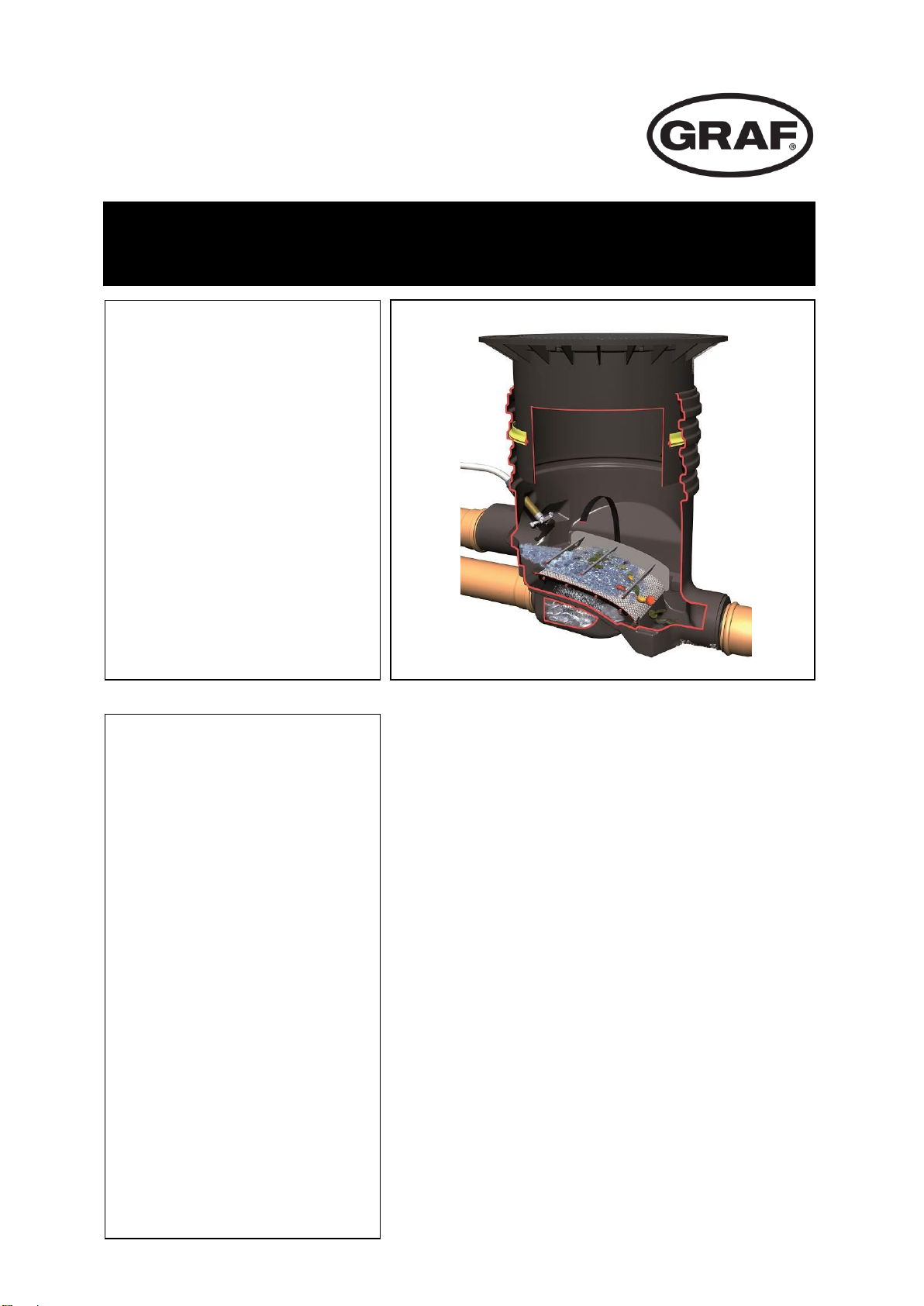
Optimax®-Industrial-Filter
external for green areas
(pedestrian weight resistant)
Order- No. 340035
Optimax®-Industrial-Filter
external for light traffic areas
Order No. 340036
The points described in these
instructions must be followed
correctly. If not correctly observed, any right to claim on the
guarantee may be refused. For
all additional GARANTIA articles purchased there are separate installation instructions enclosed in the transportation
packing.
Any missing instructions must
be requested directly from us.
A complete check of the tank for
possible damage must be carried out before the installation in
the excavation begins.
The installation must be carried
out by a professional firm.
Page 6 of 20
Installation instructions and maintenance for the
GRAF Optimax®-Industrial-Filter external
Contents
1. General notes Page 7
1.1 Safety
1.2 Labelling/Tagging obligation
2. Installation requirements Page 7
2.1 Optimax®-Industrial-Filter – pedestrian
weight resistant
2.2 Optimax®-Industrial-Filter – light traffic resistant
3. Transport and storage Page 8
3.1 Transport
3.2 Storage
4. Technical data Page 8
5. Assembly / Installation of external Page 9
Filter
5.1 Preparation of the excavation
5.2 Placing in the excavation and laying
the connections
5.3 Telescope installation
5.4 Filling Page 10
5.5 Assembly of the extraction mechanism Page 10
6. Commissioning and Service Page 10
6.1 Commissioning
6.2 Service
Page 9

1. General notes
2. Installation requirements
Page 7 of 20
1.1 Safety
When working, the appropriate accident prevention regulations (in Germany BGV C22) must
be followed. For safety reasons, especially when entering the tank, it is important that a second person is present.
Furthermore, when carrying out assembly and installation work, inspection, maintenance and
repairs, all work regulations and norms must be followed. You will find the advice in the appropriate sections of these instructions.
The installation of the system and/or single equipment parts must be carried out by a professional worker.
The complete system must always be out of operation and guarded against unauthorized
use when carrying out work on the plant or parts of the system.
The tank cover must always remain closed except when working in the tank, otherwise there
exists a very high danger of accidents. The seating and condition of the cover must be
checked on a regular basis.
The GRAF Company offers an extensive range of accessories that are all compatible with
one another and may be used to construct a complete system. The use of other manufacturer’s accessories can impair the function of the system and liability for any resulting damages
will no longer be covered under the guarantee.
1.2 Labelling/Tagging obligation
All pipe work and outlets of the water systems are to be labelled with the words “Not drinking
water” either in words or graphically (German norm DIN 1988 Part 2, paragraph 3.3.2.) so
that after years of use, an accidental connection to the drinking water system is prevented.
Even when correctly labelled it may possibly be mistaken, for example by children. For this
reason, all the outlets of the systems process water must be fitted with child safe valves.
2.1 Optimax®-Industrial-Filter external for pedestrian areas
- The Filter with the green telescopic attachment and cover may only be installed in a
green area that is not traversed by traffic.
- The amount of short-term load of the polyethylene cover is max. 150 kg, the long-term
area load max. 50 kg
- The maximum installation depth to the filter bottom is 1320 mm.
- Roof areas provided with a pipe connection of DN 150 = 750 m² and for DN 200 = 1500
m².
2.2 Optimax®-Industrial-Filter external for light traffic areas
- Through the use of the telescopic attachment (anthracite) and the cast iron cover Class B
according to DIN EN 124 the filter may be installed in areas traversed by light traffic. Under no circumstances are the tanks to be installed in areas traversed by heavy goods vehicles or machinery (see point 5.3.2)
- The earth covering above the inlet supply pipe must be at least 450 mm; the maximum
installation depth to the filter bottom is 1320 mm.
- Roof areas provided with a pipe connection of DN 150 = 750 m² and for DN 200 = 1500
m².
Page 10

Ø600 [23,6]
1180 [46,5]
92 [3,6]
Ta nk
92 [3,6]
235 [9,3]
79 [3,1]
633 [24,9]
Ø630 [24,8]
DN160
400 [15,7]
DN160
920 [36,2]
Abla uf
A-A
850 [33,5]
303 [11,9]
1180 [46,5]
Ø850 [33,5]
617 [24,3]
920 [36,2]
DN200
224 [8,8]
103 [4,0]
Stufenlose Einbautiefe von 733 -1320 m m
steplessly variable installation depth of 733-1320 mm
Zu la uf
570 [22,4]
DN 200
DN 160
303 [11,9]
375 [14,8]
Ø850 [33,5]
3. Transport and storage
4. Technical data
Page 8 of 10
Page 8 of 20
3.1 Transport
During the transport the filter must be well secured against slipping or falling. If the Filter is to
be secured for transportation with webbing straps, it is to be ensured that the filter remains
undamaged.
Stress and excess loading caused by impact are to be avoided. Under no circumstances is
the filter to be rolled or slid over the ground surface.
3.2 Storage
Any necessary temporary storage of the filter must be on an appropriate level surface without
sharp objects. During the storage it is important to avoid damage caused by the surrounding
environment or foreign objects.
Page 11

5. Assembly and installation of external Filter
Page 9 of 20
5.1 Preparation of the excavation
So that sufficient working room is available and the filter can be evenly embedded, the sur-
face area of the excavation should exceed the filter dimensions on all sides by approximately
50 cm. The excavation slope is according to DIN 4124. The installations excavation must be
level and smooth. The depth of the excavation must be measured so that the final installation
depth of the filter underside is a maximum 1320 mm. As an under surface for setting down, a
layer of smooth sand with a grain size of 8/16 according to DIN 4226 – 1 and a layer depth of
approximately 10 cm should be used.
Important: The setting down surface for the filter must be absolutely level to ensure an optional performance.
5.2 Placing in the excavation and laying the connections
The filter is installed in the prepared excavation and is then connected to the relevant pipes
etc. Attention, it is important to note that all the pipes to be installed have a must have a gradient of at least 1% in the flow direction without sagging or bending downward. To effectively
reduce the rate of flow of the incoming water, a “U” bend, similar to a siphon is installed in
the pipe before the filter. This has the effect of improving filtration and so increasing the
amount of water able to pass through the filter into the tank.
Important: It is important to follow the DIN 1986 – this requires inlet = outlet.
5.3 Telescope installation
5.3.1 Telescope pedestrian resistant
The telescope is pressed into the filter housing
from above. For excavation depths < 900 mm
the telescopic attachment and in some circumstances, the filter housing must be shortened. It is important to pay attention that the
inlet pipe is not obstructed in any way by the
telescope when installed. Before pushing in
the telescope the profiled sealing ring is
placed in the housings recess. The telescope
and the sealing ring must be thoroughly coated with the lubricating soap included in the delivery (use no lubrication that is mineral oil based). Attention: If the lubricating soap becomes dry and the telescope becomes difficult to move then there is the danger that the
sealing ring will be forced out of its recess. Before filling the sealing ring must be checked
once again that it is seated correctly in position. The telescope must be sufficiently embedded and supported that no forces are transferred to the housing.
5.3.2 Telescope suitable for light traffic
The telescope is installed as in Point 5.3.1. To ensure the function in areas traversed by light
traffic, the telescope must be embedded around the collar with lean mixed concrete. The
concrete encasement must be uninterrupted, 20 cm wide and approximately 30 cm deep.
Attention: It is important to use the cast steel cover. Transport vehicle weight of heavy
goods vehicles and machinery is not permitted. The telescope must be sufficiently embedded
and supported that no forces are transferred to the housing.
Page 12

5. Assembly and installation of external Filter
6. Commissioning and Service
Page 10 of 20
Otto Graf GmbH – Carl-Zeiss-Str. 2-6 – DE-79331 Teningen – Tél. : +49 7641 589-0 – Fax : +49 7641 589-50
GRAF Distribution S.A.R.L – 45, route d'Ernolsheim – F-67120 Dachstein Gare – Tél.:+33 388 49-7310 – Fax : +33 388 49-3280
GRAF Iberica Tecnología del Plástico S.L. – Marquès Caldes de Montbui, 114 – E-17003 Girona – Tél. : +34 972 913767 – Fax: +34 972 913766
GRAF UK Ltd – Target House – Thorpe Way Ind. Estate – Banbury – Oxfordshire – UK-OX16 4SP – Tél. : +44 1608 661-500 – Fax : + 44 1608 665-
2017-05
5.4 Filling
Important: Before and during the filling, the horizontal position of the filter must be checked.
The lengthwise embedding of the filter is with smooth sand with a grain size of 8/16 according to DIN 4226 – 1 with a width of approximately 30 cm Each layer is to be of no more than
30 cm and must be tamped down lightly with a compacting machine or hand held tamper.
Care must be taken during the embedding to ensure the filter is not damaged. To ensure that
no forces are applied to the filter housing, the telescope must be well embedded and compacted. (For areas traversed by light traffic see section 5.3.2) Finally, the cover is set in place
and secured so that it is child proof (Section 1.1 must be followed). The screws holding
down the cover are to be made so tight that they can not be removed and the cover
opened by a child!
5.5 Installation and removal (lift out mechanism)
To facilitate removal of the filter unit in cases of a deeper installation, the removal – lift out
mechanism that is included in the delivery pack should also be assembled. The screws of the
upper, mid connecting rod should be employed for the assembly.
6.1 Commissioning
Before putting the system into use the filter surface is to be thoroughly cleaned with a brush
and a solvent based cleaning fluid. Alternatively the filter sieve may be cleaned in a dish
washer (40° - max. 60°). Any dirt that gets into the filter housing during the assembly must
be thoroughly removed.
6.2 Service
The complete system is to be inspected at least every 3 months for leakage, cleanliness stability. The filters surface should be cleaned approximately every 3 months or according to
local requirements (see point 6.1).
Page 13
Filtre bâtiment Optimax
®
ex-
terne
Passage piétons
Réf. 340035
Filtre bâtiment Optimax
®
ex-
terne
Passage véhicules
Réf. 340036
Afin de garantir le bon fonctionnement et la longévité de votre
installation, il est important de
respecter scrupuleusement les
instructions de mise en place du
fabricant. Tout manquement à
ces règles annulera systématiquement la garantie. Lisez
également toutes les notices des
autres éléments fournis par la
société GRAF. Vous trouverez
les notices de montage jointes
dans l’emballage.
Contacter GRAF pour toute notice manquante.
Avant d’installer votre filtre, il est
important de vérifier que celui-ci
n’a pas été endommagé.
L'installation doit être effectuée
par un installateur professionnel.
Notice d'installation et d’entretien pour filtre
bâtiment GRAF Optimax® externe
Page 11 sur 20
Sommaire
1. Consignes générales Page 12
1.1 Sécurité
1.2 Obligation de marquage
2. Conditions d'installation Page 12
2.1 Optimax® professionnel, passage piétons
2.2 Optimax® professionnel, passage véhicules
3. Transport et stockage Page 13
3.3 Transport
3.1 Stockage
4. Caractéristiques techniques Page 13
5. Installation et montage du filtre
Optimax externe Page 14
5.1 Préparation de la fouille
5.2 Mise en place et raccordements
5.3 Montage de la rehausse télescopique
5.4 Remblaiement Page 15
5.5 Montage de l’anse de la grille filtrante Page 15
6. Mise en service et entretien Page 15
6.1 Mise en service
6.2 Entretien
Page 14

1. Consignes générales
2. Conditions d'installation
Page 12 sur 20
1.1 Sécurité
Les règles de sécurité doivent impérativement être respectées durant l’installation.
Les instructions d’installation de montage, d’entretien et de réparation indiquées ci-après,
doivent être scrupuleusement respectées.
L'installation des composants et du système doit être effectuée par un installateur profes-
sionnel.
Durant toute intervention sur la cuve ou les accessoires, l’installation complète doit être mise
hors service.
Le couvercle de protection provisoire placé sur la cuve lors de la livraison doit immédiate-
ment être remplacé par le couvercle définitif double parois en PE ou la rehausse télescopique avec couvercle en PE.
La société GRAF vous propose une gamme d’accessoires complémentaire et décline toute
responsabilité en cas d’utilisation d’article non compatible pouvant nuire au bon fonctionne-
ment de votre installation.
1.2 Obligation de marquage
Afin d’éviter toute confusion, toutes les canalisations et sorties d’eau de pluie doivent être
signalées par la mention écrite ou en image « Eau non potable ». Toutes les sorties doivent
être équipées de vannes « sécurité enfant ».
2.1 Filtre bâtiment Optimax® externe, passage piétons
- Il est interdit de circuler avec un véhicule sur le Filtre Optimax Externe – passage piétons
– rehausse télescopique couleur vert et couvercle PE couleur vert.
- Charge maximum autorisée à court terme du couvercle double parois en PE est de 150
kg, à long terme 50 kg.
- La profondeur maximale d'installation est de 1320 mm.
- Convient aux surfaces de toiture avec raccordement en DN 160 = 750 m² et
DN 200 = 1500 m²
2.2 Filtre bâtiment Optimax® externe, passage véhicules
- Passage véhicules avec rehausse télescopique (anthracite) et couvercle en fonte ca-
tégorie B. Aucun passage camions. (voir la liste au point 5.3.2)
- Remblai max. est de 450 mm, la profondeur maximale d'installation est de 1320 mm.
- Convient aux surfaces de toiture avec raccordement en DN 160 = 750 m² et
DN 200 = 1500 m²
Page 15

920 [36,2]
Cu ve
400 [15,7]
92 [3,6]
633 [24,9]
So rtie
En trée
Hauteur d'enfouissement ajustable de 733 á 1320 mm
DN 1 60
Ø850 [33,5]
617 [24,3]
920 [36,2]
DN 2 00
224 [8,8]
103 [4,0]
570 [22,4]
Ø600 [23,6]
1180 [46,5]
92 [3,6]
235 [9,3]
79 [3,1]
Ø630 [24,8]
DN 1 60
A-A
850 [33,5]
303 [11,9]
1180 [46,5]
DN 200
DN 160
303 [11,9]
375 [14,8]
Ø850 [33,5]
3. Transport et stockage
4. Caractéristiques techniques
Page 13 sur 20
3.1 Transport
Durant le transport, les filtres doivent être sécurisés afin de ne pas être endommagés et ne
pas glisser ou tomber du camion. Si les filtres sont arrimés avec des sangles, il faut s’assurer
que celles-ci n’ont pas endommagées les filtres.
Manipuler avec précaution et éviter tout coup. En aucun cas les filtres ne doivent être roulés
ou traînés sur le sol.
3.2 Stockage
Le stockage des filtres doit se faire sur un sol adapté, plat et sans objet pointu. Durant le
stockage veiller à ce qu’aucun élément extérieur ou environnemental n’endommage les filtres.
Page 16

5. Installation et montage du filtre Optimax externe
Rehausse
télescopique
Joint profilé
Pour passage véhicule
Gravier rond
Corps de filtre
Page 14 sur 20
5.1 Préparation de la fouille
Pour faciliter une bonne mise en place, prévoir une fouille minimum de 50 cm autour du filtre.
Ne pas placer le filtre au pied d’une pente ou d’un talus : le terrain doit être plan.
La profondeur de la fouille doit correspondre à la profondeur max d'installation de 1320 mm
du filtre. Disposez au fond de fouille, une couche de gravier rond 8/16 ou approchant
d’environ
10 cm d’épaisseur.
Important : Pour garantir le bon fonctionnement du filtre, celui-ci doit être posé sur un fond
parfaitement horizontal.
5.2 Mise en place et raccordements
Mettre le filtre en place dans la fouille et raccorder le aux tuyaux PVC. Ces tuyaux PVC doivent être posés avec une déclinaison de minimum 1 % et sans déformation. Raccorder le
trop-plein pour éviter une obstruction du conduit d'alimentation.
Important : Ø alimentation = Ø évacuation.
5.3 Montage de la rehausse télescopique
5.3.1 Rehausse télescopique passage piétons
Faire glisser la rehausse télescopique dans le
corps du filtre. En cas de profondeur de fouille
< 930 mm, la rehausse et éventuellement le corps
du filtre doivent être raccourcis. Vérifier que le
manchon d’arrivée ne soit pas partiellement ou
entièrement obstrué par la rehausse. Avant de
positionner la rehausse, insérez le joint
d’étanchéité dans la rainure du corps du filtre.
Enduisez ensuite généreusement le joint et la
rehausse avec la graisse blanche (ne pas utiliser de graisse à base d’huile minérale, trop
agressive pour le joint).
Attention : Ne laissez pas sécher la graisse blanche : le positionnement de la rehausse sera
plus difficile et le joint profilé risque de se déloger de la rainure et l’étanchéité ne sera plus
garantie. Tassez bien le remblai autour de la rehausse manuellement, de sorte qu’aucune
pression extérieure ne modifie son positionnement.
5.3.2 Rehausse télescopique passage véhicules
Le montage de la rehausse télescopique s'effectue comme indiqué au point 5.3.1. Sceller la
rehausse télescopique dans une dalle de répartition en béton. La couche de béton doit être
d'au moins 30 cm de largeur et environ 20 cm d'épaisseur.
Attention : Il faut impérativement utiliser un couvercle en fonte et acier. Aucun passage
camions. Tassez bien le remblai manuellement autour de la rehausse télescopique pour
éviter le transfert des charges sur le filtre.
Page 17

5. Installation et montage du filtre Optimax externe
6. Mise en service et entretien
Otto Graf GmbH – Carl-Zeiss-Str. 2-6 – DE-79331 Teningen – Tél. : +49 7641 589-0 – Fax : +49 7641 589-50
GRAF Distribution S.A.R.L – 45, route d'Ernolsheim – F-67120 Dachstein Gare – Tél.:+33 388 49-7310 – Fax : +33 388 49-3280
GRAF Iberica Tecnología del Plástico S.L. – Marquès Caldes de Montbui, 114 – E-17003 Girona – Tél. : +34 972 913767 – Fax: +34 972 913766
GRAF UK Ltd – Target House – Thorpe Way Ind. Estate – Banbury – Oxfordshire – UK-OX16 4SP – Tél. : +44 1608 661-500 – Fax : + 44 1608 665-
2017-05
Page 15 sur 20
5.4 Remblaiement
Vérifier le positionnement horizontal du filtre avant et pendant le remblaiement. Remblayer
avec du gravier rond 8/16 ou approchant sur environ 30 cm autour du filtre, par couches
successives de 30 cm de hauteur. Tassez avec une petite compacteuse manuelle. Veillez à
ne pas endommager le filtre. Tasser manuellement le remblai autour de la rehausse télescopique, de sorte qu’aucune pression extérieure ne modifie son positionnement et pour
éviter le transfert des charges sur le filtre (Avec passage véhicule voir point 5.3.2)
Positionnez et verrouillez le couvercle (sécurité enfant) respecter les consignes de la section
1.1. Serrez suffisamment le boulon afin qu’un enfant ne puisse pas l’ouvrir !!
5.5 Montage de l’anse de la grille filtrante
Afin de pouvoir retirer facilement la grille filtrante, monter l’anse percée fournie en utilisant
les vis de la barre de liaison de la grille filtrante.
6.1 Mise en service
Avant la mise en service, nettoyer soigneusement la grille filtrante avec une brosse et un
produit dégraissant ou placer la dans le lave-vaisselle (40 °C - max. 60 °C). Retirer les salissures éventuelles du corps du filtre liés au montage.
6.2 Maintenance
Vérifier environ tous les 3 mois, la propreté, l’étanchéité et le bon positionnement de
l’ensemble. Un nettoyage de la grille filtrante s’impose selon l’emplacement et le lieu
d’habitation (éventuellement davantage en automne voir le point 6.1).
Page 18

Optimax®-Filtro Externo
para zonas verdes
(transitable por peatones)
Código 340035
Optimax®-Filtro Externo
transitable por turismos
Código 340036
Los puntos descritos en estas
instrucciones deben ser
respetados obligatoriamente. Si
no se observan las
instrucciones prescribe todo
derecho de garantía. Recibirá
adjuntas en el embalaje de
transporte por separado las
instrucciones de instalación
para todos los artículos
adicionales adquiridos a GRAF.
Rogamos nos soliciten
inmediatamente las
instrucciones que faltan.
Antes de trasladar los depósitos
a la excavación examine sin
falta los componentes para
detectar eventuales
desperfectos.
La instalación debe ser
realizada por una empresa
Instrucciones de instalación y mantenimiento
GRAF Optimax®-Filtro Externo
Página 16 de 20
Í
ndice de contenido
1. Allgemeine Hinweise Página 17
1.1 Seguridad
2. Condiciones para la instalación Página 17
2.1 Optimax®-Filtro Externo transitable por peatones
2.2 Optimax®-Filtro Externo transitable por turismos
3. Transporte y almacenamiento Página 18
3.1 Transporte
3.2 Almacentamiento
4. Datos técnico Página 18
5. Instalación / montaje filtros externos Página 19
5.1 Preparatión de la excavación
5.2 Inserta el filtro y realizar las conexiones
5.3 Montar el suplemento telescópico
5.4 Compactado Página 20
5.5 Montaje del dispositivo de extracción Página 20
6. Puesta en servico y mantenimiento Página 20
6.1 Puesta en servico
6.2 Mantanimiento
Page 19

1. Indicaciones generales
2. Condiciones para la instalación
Página 17 de 20
1.1 Seguridad
Para la ejecución de todos los trabajos deben seguirse las prescripciones pertinentes de
prevención de accidentes según las normas C22 de la Asociación profesional.
Especialmente cuando se inspeccionan los depósitos es necesaria una segunda persona
como medida de seguridad.
Aparte de esto se deben seguir las prescripciones y normas correspondientes para la
ejecución de los trabajos de instalación, montaje, mantenimiento, reparación, etc.
Encontrará indicaciones al respecto en los capítulos correspondientes de estas
instrucciones.
La instalación de este equipo o de las piezas individuales del mismo se debe confiar siempre
a personal técnico cualificado.
Antes de realizar cualquier trabajo en la instalación o en piezas individuales de la misma
debe ponerse toda la instalación fuera de servicio, protegiéndola al mismo tiempo contra una
puesta en marcha no autorizada.
Excepto durante la realización de los trabajos necesarios en el filtro se deberá mantener
siempre cerrada la tapa. En caso contrario existe un riesgo altísimo de accidente. Hay que
controlar periódicamente que la tapa esté correctamente cerrada.
GRAF ofrece un amplio surtido de accesorios que han sido adaptados entre sí y que pueden
ampliarse para formar sistemas completos. La utilización de otros accesorios puede
provocar la pérdida de funcionalidad de la instalación, de modo que el fabricante no asume
ninguna responsabilidad sobre los daños generados en estos casos.
Obligatoriedad de identificación
Todas las tuberías y puntos de agua no tratada se deberán identificar de forma textual con
las palabras "No es agua potable" o mediante un pictograma (DIN 1988 Parte 2, apdo.
3.3.2.), con el fin de prevenir la conexión por error a la red de agua potable. Incluso siendo la
señalización correcta pueden producirse confusiones, p. ej. por parte de niños. Por esta
razón se deberán instalar válvulas con seguro a prueba de niños en todos los puntos de
agua no tratada.
2.1 Optimax®-Filtro Externo transitable por peatones
- El filtro con el suplemento telescópico y la tapa PE verde sólo se puede montar en zonas
verdes no transitadas por vehículos.
- La tapa de PE resiste durante un corto periodo de tiempo el tránsito por peatones con un
peso máx. de 150 kg, y si es durante un tiempo prolongado, de como máximo 50 kg.
- La profundidad máxima de montaje hasta el fondo del filtro es de 1320 mm
- La superficie de cubierta admisible con conexión es: para DN 150 = 750 m², para DN
200 = 1500 m²
2.2 Optimax®-Filtro Externo transitable por turismos
- Utilizando el suplemento telescópico (color antracita) y la cubierta de fundición clase B
según UNE EN 124 se puede instalar el filtro debajo de superficies transitadas por
turismos. No se debe instalar el filtro nunca debajo de superficies transitadas por
camiones. (ver el apdo. 5.3.2)La cobertura con tierra por encima del tubo de entrada es
de como mín. 450 mm, la profundidad de montaje máx. hasta el fondo del filtro es de 320
mm.La superficie de cubierta admisible con conexión es: para DN 150 = 750 m², para DN
200 = 1500 m²
Page 20

Ø600 [23,6]
1180 [46,5]
92 [3,6]
Ta nk
92 [3,6]
235 [9,3]
79 [3,1]
633 [24,9]
Ø630 [24,8]
DN 1 60
400 [15,7]
DN 1 60
920 [36,2]
Ab la uf
A-A
850 [33,5]
303 [11,9]
1180 [46,5]
Ø850 [33,5]
617 [24,3]
920 [36,2]
DN 2 00
224 [8,8]
103 [4,0]
Stufenlose Einbautiefe von 733 -1320 m m
steplessly variable installatio n depth of 733-1320 mm
Zu la uf
570 [22,4]
DN 200
DN 160
303 [11,9]
375 [14,8]
Ø850 [33,5]
3. Transporte y almacenamiento
4. Datos técnicos
Página 18 de 20
3.1 Transporte
Durante el transporte deben asegurarse los filtros contra deslizamientos y caídas. Si se
aseguran los filtros con cintas de amarre para su transporte, debe garantizarse que no
sufrirán daños.
Hay que evitar siempre los golpes e impactos. No rodar ni arrastrar en ningún caso los filtros
sobre la superficie.
3.2 Almacenamiento
En caso de resultar necesario un almacenamiento provisional de los filtros, éste deberá
realizarse sobre una superficie plana adecuada. Durante el periodo de almacenamiento
debe evitarse todo daño ocasionado por factores medioambientales o externos.
Page 21

5. Instalación / montaje filtros externos
Hormigón
(para el tránsito de vehículos
Grava redonda
Cuerpo de filtro
Suplemento
telescópico
Junta perfilada
Página 19 de 20
5.1 Preparación de la excavación
Las medidas del agujero deben superar las medidas del filtro en ambos lados en 50 cm con
el fin de que quede suficiente espacio de trabajo y que el filtro se pueda compactar
uniformemente. El talud se debe realizar según la norma DIN 4124. El terreno debe ser
horizontal y liso. La profundidad de la excavación debe estar dimensionada de forma que la
profundidad de montaje hasta el fondo del filtro sea como máximo de 1320 mm. Como base
se debe preparar una capa de grava redonda compactada (tamaño 8/16 según DIN 4226- 1,
espesor aprox. 10 cm). .
Importante: la superficie de apoyo para el filtro tiene que ser totalmente horizontal para
garantizar el funcionamiento en condiciones óptimas.
5.2 Insertar el filtro y realizar las conexiones
Insertar el filtro en el agujero y conectarlo a las tuberías. Es importante que todas las
tuberías se tiendan con una pendiente inclinada en el sentido del flujo de como mín. el 1%.
Para reducir la velocidad del flujo del agua que entra hay que instalar el tubo de entrada
antes de la entrada del filtro en forma de "U", similar a un sifón. Esto tiene el efecto de
mejorar considerablemente el aprovechamiento del agua.
Indicación importante: Es imprescindible observar la norma DIN 1986, es decir, Ø entrada
= Ø salida.
5.3 Montar el suplemento telescópico
5.3.1 Suplemento telescópico transitable
por peatones
Insertar el suplemento telescópico desde arriba
en el cuerpo del filtro. Si la excavación tiene una
profundidad < 900 mm hay que acortar el
suplemento telescópico y eventualmente el
cuerpo del filtro. Es muy importante que cuando
todo esté definitivamente montado el
suplemento telescópico no tape las tuberías de
entrada totalmente o en parte. Antes de
insertarla hay que colocar la junta de estanqueidad perfilada en la ranura estanqueizante del
cuerpo del filtro. Hay que aplicar una capa generosa del jabón blando incluido en el
suministro (no utilizar lubricantes a base de aceites minerales) sobre el suplemento
telescópico y la junta. Si el jabón blando se seca el suplemento telescópico tiene poca
movilidad y existe el riesgo de que la junta salga de la ranura. Antes de proceder al
compactado hay que comprobar el asiento correcto de la junta. El suplemento telescópico
tiene que estar suficientemente recalzado para evitar que en ningún caso las fuerzas se
transmitan al cuerpo del filtro.
5.3.2 Suplemento telescópico transitable por turismos
Montar el suplemento telescópico según lo explicado en el punto 5.3.1. Para asegurar la
transitabilidad por turismos hay que recalzar el collarín del suplemento telescópico con
hormigón. La capa de hormigón a poner en obra deberá presentar una anchura mínima de
20 cm y un grosor de aprox. 30 cm. Atención: Es imprescindible usar la cubierta de
fundición de acero. No se admiten cargas por el tránsito de camiones. El suplemento
telescópico tiene que estar suficientemente recalzado para evitar que las fuerzas se
transmitan al cuerpo del filtro.
Page 22

5. Instalación / montaje filtros externos
6. Puesta en servicio y mantenimiento
Otto Graf GmbH – Carl-Zeiss-Str. 2-6 – DE-79331 Teningen – Tel.: +49 7641 589-0 – Fax: +49 7641 589-50
GRAF Distribution S.A.R.L – 45, route d´Ernolsheim – FR-67120 Dachstein Gare – Tél.:+33 388 49-7310 – Fax: +33 388 49-3280
GRAF Iberica Tecnología del Plástico S.L. – Marquès Caldes de Montbui, 114 – ES-17003 Girona – Tel.: +34 972 913767 – Fax: +34 972 913766
GRAF UK Ltd – Target House – Thorpe Way Ind. Estate – Banbury – Oxfordshire – UK-OX16 4SP – Tel.: +44 1608 661-500 – Fax: + 44 1608 665-466
2017-05
Página 20 de 20
5.4 Compactado
Antes y durante el compactado es imprescindible que se controle que la posición del filtro
sea horizontal. La capa envolvente del filtro se realiza con grava redonda (tamaño 8/16
según DIN 4226-1) 4226 – 1) , capa a capa, con un grosor de aprox. 30 cm. Las distintas
capas se deben colocar hasta una altura de 30 cm compactándolas seguidamente con un
compactador ligero (pisón manual o algo similar). Evitar dañar el cuerpo del filtro durante la
compactación. Hay que recalzar el suplemento telescópico para evitar que se transmitan
fuerzas al cuerpo del filtro. (en el caso de superficies transitadas por turismos hay que
observar el apartado 5.3.2.) A continuación colocar la tapa y cerrarla a prueba de niños
(observar el apartado 1.1). ¡Hay que apretar los tornillos en la tapa con suficiente fuerza
para que un niño no pueda abrirla!
5.5 Montaje del dispositivo de extracción
Para poder retirar el filtro intercambiable, incluso bajo coberturas de tierra más grandes,
habría que montar el dispositivo de extracción incluido en el suministro. Para realizar el
montaje hay que atornillar los tornillos de la barra de unión superior central.
6.1. Puesta en servicio
Antes de la puesta en servicio hay que limpiar la superficie del filtro a fondo con un cepillo y
detergente desengrasante. De forma alternativa es también posible la limpieza en un
lavaplatos (40° - máx. 60°). Hay que eliminar la suciedad que ha penetrado en el cuerpo del
filtro durante el montaje.
6.2. Mantenimiento
Comprobar la estanqueidad, limpieza y estabilidad de la instalación, como mínimo, cada tres
meses. Hay que limpiar la superficie del filtro aprox. cada 3 meses (según las condiciones
locales incluso con mayor frecuencia) (ver punto 6.1.).
 Loading...