

Page 1

1 / 40
Instructions for
start-up, operation and maintenance
one2clean+
one2clean+ XXL
Small wastewater treatment
systems
Control unit version KL24plus
The points described in these instructions must be observed in all
cases. Failure to do so shall invalidate the warranty. For any additional items purchased through
GRAF, you will receive separate
installation instructions in the
transport packaging.
The components must be checked
for any damage before the system
is transferred to the pit.
You will receive separate instructions for installation of the system.
Be sure to read before starting
up!
Contents
1. General information 2
2. Safety 3
3. Description of function 6
4. Control unit 8
5. Start-up 18
6. Level measurement 19
7. Operation and maintenance 22
8. Fault messages and rectification 28
9. EC conformity declaration 31
10. Technical data 32
11. Template for weekly / monthly check notes 34
12. Maintenance log for GRAF small wastewater
treatment systems 37
13. Notes 39
Page 2

1. General information
2 / 40
1. General information
Below you will find some important information for safely operating your system for a long time to come.
• The SBR system is designed to receive all domestic wastewater. Other wastewater, e.g. from restau-
rants and / or commercial premises etc., may only be received if this was specified and taken into
account in the system's design.
• Biocides, toxic substances or substances which are not biocompatible must not enter this system
because they hinder bacteria important to wastewater cleaning and cause problems in the biological
process (detailed information is provided on the following pages).
To meet official cleaning requirements, it is essential that the system is operated in accordance
with our operating and maintenance instructions. You will find these instructions on the following
pages.
We also ask you to read the following information carefully:
The External control cabinets should be located as much in the shade as possible to prevent
them from overheating in the summer.
At all times ensure that the cabinet, especially its ventilation apertures, are not covered and are
freely accessible for maintenance work.
External control cabinet: Ventilation apertures on the rear
The power supply must be ensured at all times. Please ensure that the fuse on the control cabi-
net is sufficient (16 A). Additional electrical fixtures on the same fuse may disrupt operation.
Page 3
2. Safety
3 / 40
2. Safety
This chapter contains details relating to safety measures and residual risks. Read this chapter through
carefully before using the system to ensure that it is used as safely as possible.
Intended use 2.1
The control unit was specifically developed for use in SBR small wastewater treatment systems. The control unit must not be used in areas representing a danger to life and limb:
control of machinery, vehicles and safety processes,
research technology involving hazardous substances,
medical technology,
nuclear power technology,
etc.
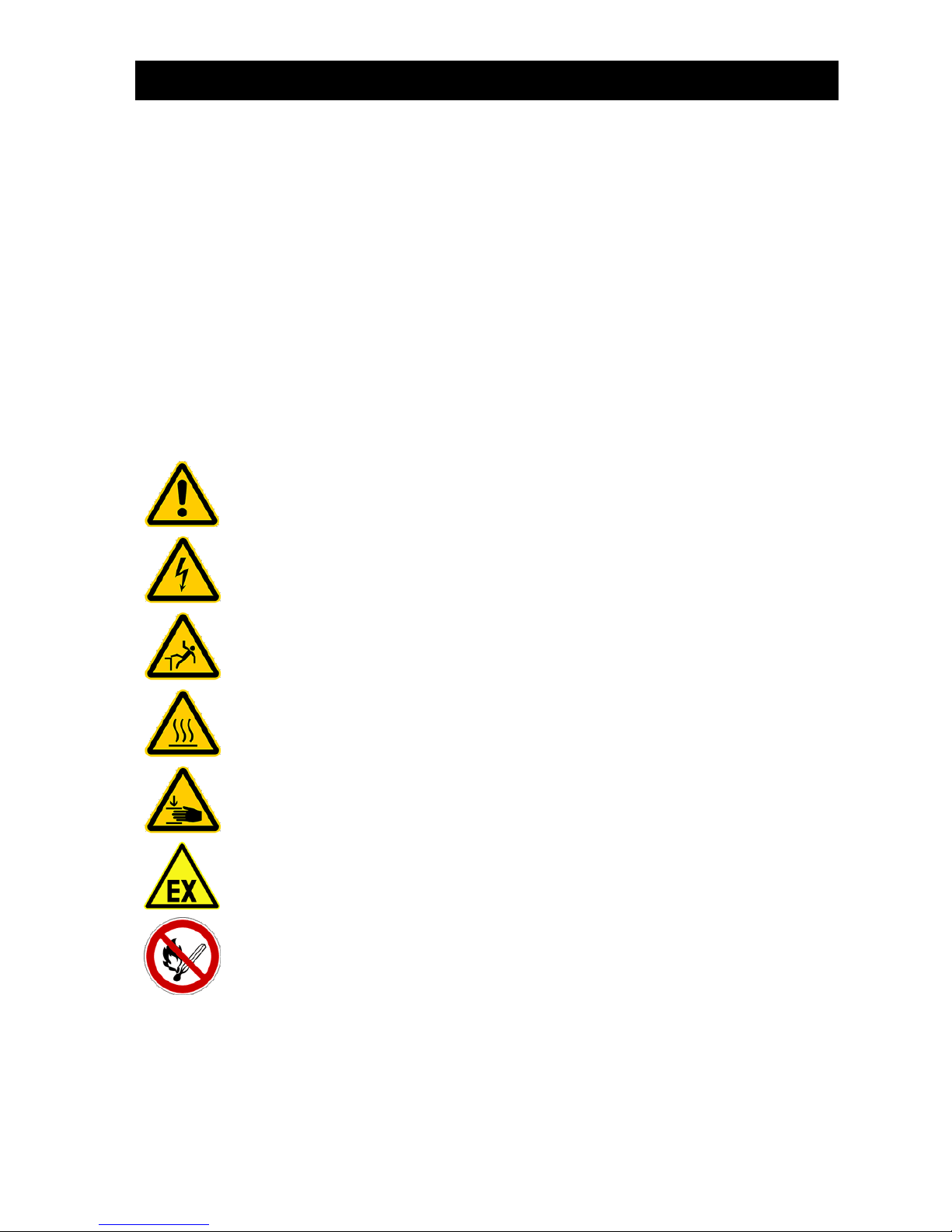
Explanation of warning notices and prohibitions 2.2
Warning of danger
Warning of dangerous voltage
Warning of tripping risk
Warning of hot surface
Warning of hand injuries
Warning of explosive atmospheres
Fire, naked flames and smoking prohibited
Page 4

2. Safety
4 / 40
Danger notices 2.3
1. To ensure safety, everyone who comes into direct contact with the system must note the content of
this documentation.
2. The system must not be used for any purpose other than that described by the manufacturer.
3. Local operating and safety requirements and legislation must be followed at all times, even if they
are not explicitly mentioned in these instructions. The same applies to environmental requirements.
4. If the operator becomes aware of mistakes or dangers, the manufacturer or responsible maintenance company must be informed immediately.
5. Safety precautions must never be removed or bypassed during normal operation of the wastewater
treatment system. Safety precautions may only be temporarily bypassed or deactivated by the
maintenance fitter during repairs and maintenance.
6. When working with chemical substances, contact with the chemicals should be avoided Before these substances may be used, the instructions for use on the packaging must be read and followed.
7. If the use of personal protective equipment (safety shoes, protective glasses, gloves, ear defenders,
etc.) is prescribed, ensure that they are used. Defective or damaged protective equipment must be
immediately replaced with fully functional equipment.
8. Work on electrical equipment may only be undertaken by specialists.
9. All safety and danger notices on the machine should always be kept fully legible.
10. Hot parts must not come into contact with explosive or highly flammable chemicals.
11. Do not put vessels containing liquids on electric switch cabinets; short circuits may occur if the liquid
is spilled.
12. The system must not be operated by anyone under the influence of alcohol or medication which limits cognitive ability or ability to react.
13. The system must be de-energised before any maintenance or cleaning work takes place.
14. Other than for maintenance purposes, the system should always be left switched on, otherwise correct wastewater cleaning cannot be guaranteed.
Page 5
2. Safety
5 / 40
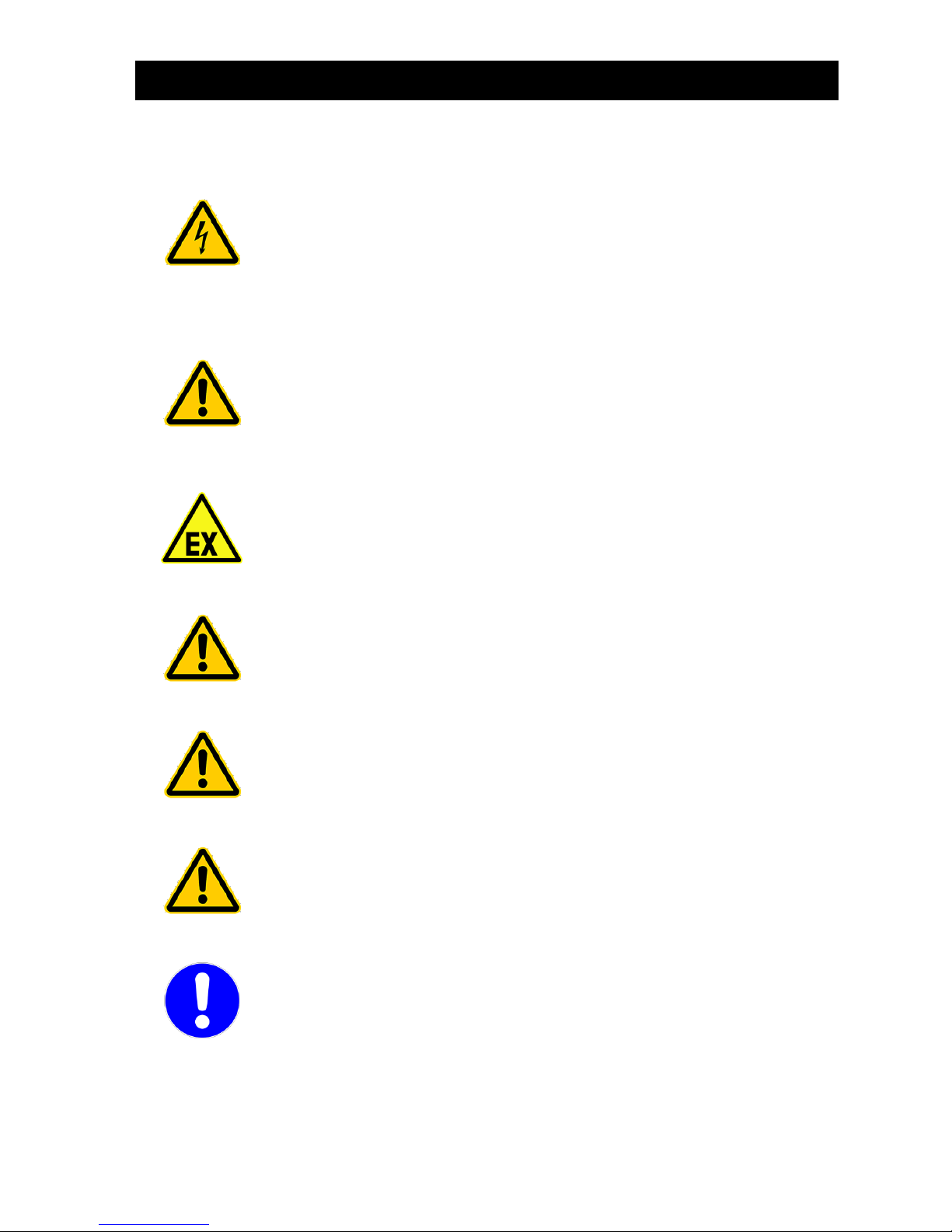
Warning notices 2.4
Be sure to observe this information. Failure to do so may result in personal injury or damage to property!
Installation loca-
tion
Ensure that the machine cabinet is not installed above or in the direct vicinity of water
vessels. There is a risk of electric shock if improperly installed.
Mains connection
Only connect the machine cabinet to a correctly installed 230 V socket or earth cable
which is fused with an upstream 16 A fuse.
Electrical equipment connected to the mains may be damaged during a storm. We
would recommend fitting surge protection in the building to protect against this.
The connection cable must be laid in a way it won’t represent a tripping hazard.
Explosive atmos-
pheres
The control unit must not be fitted or activated in environments with potential explosive atmospheres or in places where there are flammable materials. Sparks in such
environments may cause an explosion or fire and this may result in physical injuries
or even death.
Interferences
The control unit may cause medical equipment to malfunction. This device should
therefore not be used in close proximity to medical equipment.
Damage
The control unit must not be operated if the housing or cable insulation is damaged or
crushed.
Service work
Service work on the machine cabinet may only be undertaken by authorised specialists / electricians.
Voltage supply
The power supply must be ensured at all times. Please ensure that the fuse on the
control cabinet is sufficient (16 A). Additional electrical fixtures on the same fuse may
disrupt operation.
Page 6
3. Description of function
6 / 40
3. Description of function
Description of the wastewater treatment process 3.1
The one2clean+ wastewater treatment system is a fully biological system and functions on the principle of
the retention process with extended aeration (Sequencing Batch Reactor). The system basically consists
of an aerobic stage, which is split into a rest and an aeration zone, linked together in the lower section.
This process therefore subjects all the domestic wastewater directly to aerobic wastewater treatment.
Blowing in compressed air aerates the entire system and the resultant aerated sludge biologically cleans
the wastewater.
The coarse materials and floating solids in the wastewater are initially retained using a scum guard in the
rest zone. Then the wastewater passes into the aeration zone via an aperture under the scum guard.
The rest zone is aerated too, so the retained solids are also aerobically broken down over the course of
time. In the one2clean+, the wastewater is treated without pre-treatment so no anaerobic putrefaction
processes can occur.
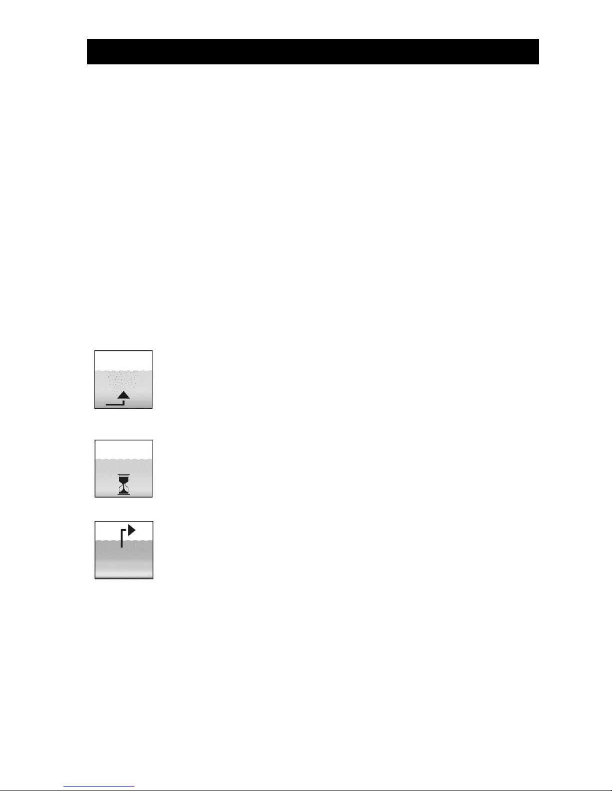
The SBR procedure is a series of different steps, undertaken one after another and at least once a day.
Step 1: Aeration
In the first phase, the wastewater is put straight through aerobic treatment for a fixed
time. As a result, the microorganisms (aerated sludge) are supplied with the oxygen
needed for the breakdown and then pressure aeration causes mixing. The system's
aeration equipment is supplied with ambient air by a compressor. Aeration is intermittent so that targeted wastewater cleaning is possible. Different ambient conditions can
thereby be achieved.
Step 2: Settle
There is no aeration in the second phase. The aerated sludge and the remaining settleable solids can now settle with the aid of gravity. A clear water zone forms at the top
and a sludge layer at the bottom. Any floating sludge is on top of the clear water zone.
Step 3: Clear water extraction
In this phase, the biologically cleaned wastewater (clear water) is drawn out of the SBR
stage. It is pumped out by an air lift (or mammoth) pump, which uses compressed air.
The air lift pump is designed not to pump out any floating sludge on top of the clear
water layer. A minimum water level is maintained in the system without any further
components.
In multi-tank systems, there is also a phase in which the sludge is returned to the system.
Once step is complete, the cleaning process starts again with step 1.
Two cycles are undertaken a day. The maintenance company can individually adapt the switching times.
Page 7

3. Description of function
7 / 40
Structure of one-tank systems 3.2
Figure 1: One-tank system
Structure of multi-tank systems 3.3
Figure 2: Two-tank system
Sampling point
Clear water lifter
Scum baffle
Pipediffusors
Sampling point
Clear water lifter
Pipe Diffusors
Pipediffusors
Sludge return
Connection pipe
Page 8

4. Control unit
8 / 40
4. Control unit
Connections to the KL24plus control unit 4.1
The figures below show the basic structure of the switch cabinet of a two-tank system.
Figure 3: EPP cabinet with 3-way air distributor
The following connections can be found on the switch cabinet:
1. 230V AV ~ 50 Hz mains connection, for connecting the control unit to a socket
2. Compressor connection, for connecting the
compressor to the control unit via an integrated two pin plug
3. Compressor's air connection. This is used to
connect the strip of valves integrated in the
switch box to the compressor
4. Hose connection (19 mm) for connecting the
aeration unit
5. Hose connection (13 mm) for connecting the
discharge lifter
6. Hose connection (13 mm) for connecting the
sludge lifter
7. One unused hose connection
Figure 4: Air distributor with stepped motors
Y4
Y3 Y2
Compressor
Compressor connection
Connection for power supply
Connection 6 mm
for level sensor
aeration
sludge lifter
discharge lifter
(two tank systems)
Control unit
Page 9
4. Control unit
9 / 40
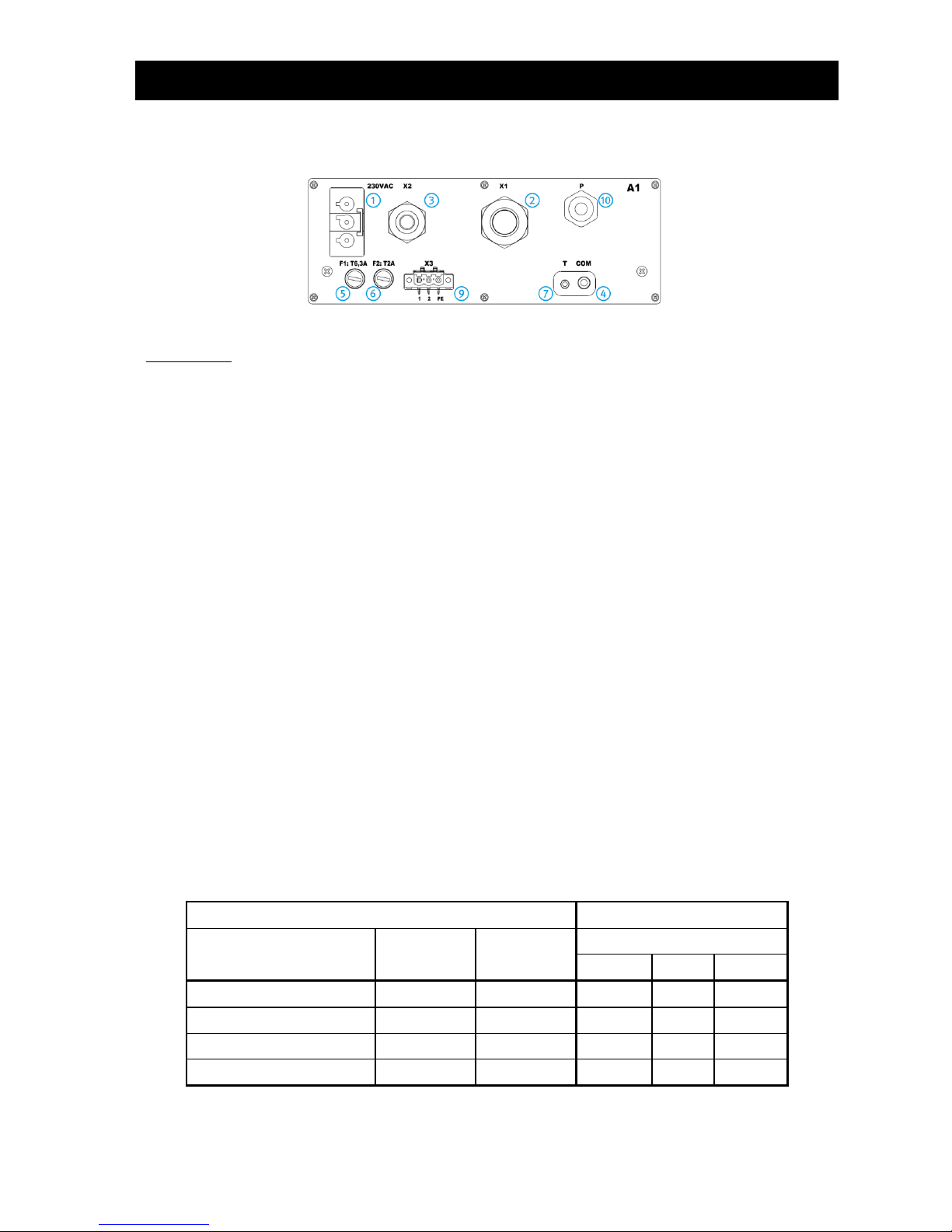
Connections on the rear of the control unit 4.2
Figure 5: Rear of KL24plus control unit
Connections:
1 Connection for mains cable
230 V AC ~ 50 Hz
2 X1: Pre-assembled valve cable
3 X2: two pin plugs for the air compressor connection
4 COM: Connection for communication module (optional) and/or port for PC
5 F1: T6.3A main fuse, slow blow
6 F2: T2A fuse for UV module, slow blow
7 Connection for temperature sensor, "must be plugged in!"
9 X3: Connection for UV module
10 P: Connection for pressure measuring hose
Connections on the air distributor/valve block 4.3
When delivered, the control unit is already correctly connected to the corresponding connection on the air
distributor/valve block.
A distinction is made between three different air distributor variants:
1. 4-way air distributor (4 separate valves Y1 …Y4)
2. 3-way air distributor (3 separate valves Y2 …Y4) and
3. 2-way air distributor (2 separate valves Y3 and Y4)
To allow you to correctly connect up at a later date, the connectors of the control unit (X1.1 …X1.4), their
function (aeration, clear water extraction or sludge extraction) and the connections on the air distributor in
a matrix are shown in detail in the table below.
Control unit
Air distributor connections
Functions
Valves
Connectors
3-way
Y2
Y3
Y4
Aeration
Valve 1
X1.1
X
Clear water extraction
Valve 2
X1.2
X
Sludge Return
Valve 3
X1.3
X
-----
Valve 4
X1.4
Page 10

4. Control unit
10 / 40
Starting up the control unit 4.4
Once the system has been connected to the power supply, perform a brief system test. The system test
takes a few seconds and checks the real-time buffering. During this time, the LED lights up red. Then the
LED switches to green and the start phase is complete. During the system test the words "SYSTEM TEST
... OK" appear. The program version and the control unit's serial number are displayed briefly. The system's current operating mode is then displayed in the liquid crystal display. Once the system test is complete, the date and current time should be checked and adjusted if necessary.
After checking the date/time, the function of the installed parts should be checked. The check can only
take place as soon as the installed parts are connected to the control cabinet via the air hoses needed.
The check should be carried out via the "Manual operation" menu item in the control unit. The individual
installed parts should be activated and checked in turn.
The system should be reset to automatic mode once the check is completed successfully.
PLEASE NOTE: The clear water lifter will only work if the tanks are filled.
If the time and date are not set correctly, operating faults are saved with the wrong times.
Page 11
4. Control unit
11 / 40
Instructions for operating the wastewater treatment system 4.5
The system is operated using a microprocessor in the control unit. The microprocessor allows operating
parameters to be set, operating statuses to be displayed, system parameters to be queried and operating
times to be programmed by a specialist.
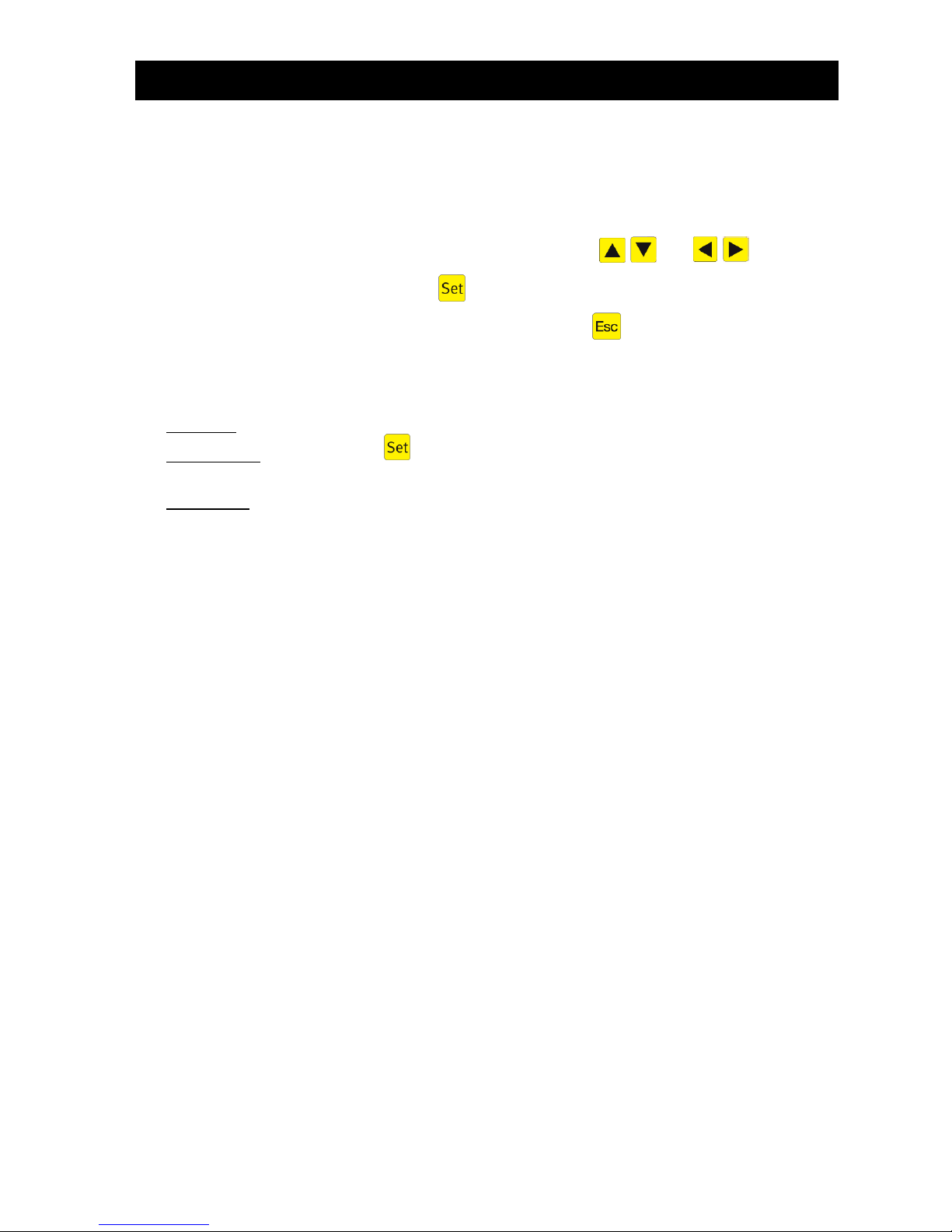
Settings are entered by scrolling through numerical values using the and arrow keys.
The setting is then confirmed by pressing the key.
The individual dialogues can be closed prematurely by pressing or close automatically after 2
minutes.
The control unit is divided into the following display screens:
1. Basic level: Status of cycle process with remaining time elapsing and fault message display.
2. Operator level: By pressing the key, the operator can enter the operator level and undertake
operator-specific settings.
3. Service level: A password-protected service level is accessed from the operator level via an additional
code. This level is reserved for trained staff. Settings and/or changes can be undertaken here and diagnosis data called up.
4.5.1 Control programs
The control unit switches the outputs for air compressors and valves at specific times.
The times are defined by the set sequence tables.
In accordance with the sequence table selected, a complete cleaning cycle is started at each start time.
Setting holiday times at operator level enables all cleaning cycles to be suppressed for the set time period. Only a holiday cycle with greatly reduced activity occurs during this time. No treated wastewater is
extracted during this time because no water should be fed in.
The current sequence table can be modified by trained staff in the service level. Depending on the size of
the wastewater treatment system, another sequence table can be selected. The current sequence table
and other settings are stored resistant to zero voltage. The current sequence table is only modified or a
new sequence table selected in the cycle pause. This ensures that the current extraction is always undertaken at the end of a complete cleaning cycle.
If this is not necessary, the user can perform a "Cycle restart" to immediately adopt the modified parameters.
A sequence table consists of:
• table name - comprising max. 16 characters, e.g. one2clean+ 4PE C
• number of start times (cycles) - max. 24
• cycles - with cycle times and the consumers to be switched
Page 12
4. Control unit
12 / 40
4.5.2 Operating status display
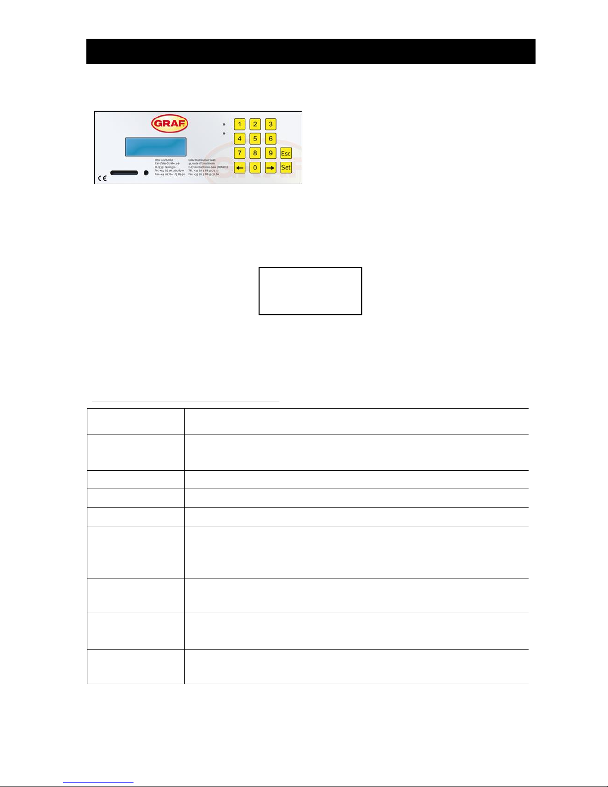
Figure 6 View of KL24plus operating unit
The system's operating status is indicated by the LEDs (Green = Operation / Red = Fault) and by text on
the screen.
In normal operating mode (aeration mode), the display looks like this:
In automatic mode, the liquid crystal display shows the current operating phase and time remaining in this
stage of operation.
If a fault occurs, the red LED switches on. A message appears in the liquid crystal display indicating
which component is faulty (e.g. compressor 0.0A fault).
The following operating phases are displayed:
KL24plus
Control unit
Process undertaken
Denitrification
Aeration is activated intermittently, the aerated sludge is briefly mixed. There are
long pauses in between (reaction times).
Aeration
Aeration is activated, the system is aerated at intervals.
Settling phase
Rest phase; the aerated sludge settles.
Discharge phase
Discharge lifter is activated, the clear water is pumped into the discharge.
Sludge removal
Sludge lifter is activated, the excess sludge is pumped out of the last tank back
into the first one.
ONLY with multi-tank systems
Cycle pause
Aeration is activated, the system is aerated at intervals (considerably less than in
the "aeration" phase).
Holiday mode
Aeration is activated, the system is aerated at intervals, no cleaning cycles are
undertaken.
Remaining: XXX.XX
min
Display showing time remaining.
Aeration
Remaining:
120:10min
Page 13

4. Control unit
13 / 40
Operating the control unit 4.6
You can start various queries when in automatic mode.
Pressing takes you to the first operating level. Now you can call up the individual queries by pressing
the two arrow keys and followed by :
Display
KL24plus
Meaning
Operating mode
Remaining time
Time remaining in current operating phase
Operating hours
counter reading
Operating hours display for individual valves and compressor
Manual mode
function
Manual activation of valves
Date
time
Current time, day and date. Can be set by pressing SET
Holiday mode
set date
Set holiday mode (max. 90 days)
Read out old
faults
Operational faults are saved here and can be read out. Press to switch between the error message and the associated date
Display
settings
The current settings can be viewed using the arrow keys
Action code
For specialists
Enter service
menu code
For specialists
4.6.1 Operating hours query
Press the key. Screen shows:
By again pressing , the operating hours can be called up for valves, compressor and house pump in
turn using the arrow keys and .
Pressing once takes you back to the "Operating hours" display.
Note: If no key is pressed for 10 minutes, normal mode engages automatically.
Operating hours
Page 14

4. Control unit
14 / 40
4.6.2 Manually controlling the valves and cabinet fan using "Manual mode"
Press , then press the arrow key until the following appears on screen:
Manual mode can now be set for all functions by again pressing and using the arrow keys to
make the relevant selection.
Taking the example of valve 1, the screen now shows:
By selecting "1" for "ON" and "0" for "OFF", valve 1 can be activated and deactivated in manual mode.
You can proceed in the same way with the other valves. The valves are selected with the arrow keys
as described above.
Pressing the key once takes you back to the maintenance level. And pressing again restores automatic mode.
Note: Each valve should run for at least 5 seconds when testing because it takes some time to
monitor the power consumption of valves before any faults are detected. After the valves,
the cabinet fan (if fitted) can also be activated and checked.
Manual mode
function
Manual mode
Valve1: OFF
Page 15

4. Control unit
15 / 40
4.6.3 Setting date/time
Press , then press the arrow keys until the following appears on screen (example):
By pressing you can set the time and date using the arrow keys . To confirm each change,
you must press .
Pressing once takes you back on to holiday mode. Pressing takes you back to manual mode.
Note: The system's time and date MUST be set correctly to ensure accurate recording of operat-
ing hours and any malfunctions that may occur. The built-in clock has a maximum deviation
of 5 minutes per year. There is no automatic switchover from summer to winter time.
If no key is pressed for 10 minutes, normal mode engages automatically.
4.6.4 Setting holiday mode
Note: The wastewater treatment system has a reduced operation when in holiday mode. This
mode should only be used if no wastewater will be fed into the wastewater treatment system
during the selected period. Wastewater which does enter the system during holiday mode is
not cleaned. Holiday mode is automatically activated and deactivated on the dates entered.
Press , then press the arrow keys until the following appears on screen:
The input of holiday data is released by again pressing :
Start of holiday:
Pressing enters the year, month and day in the format YY-MM-DD. should be pressed each
time a year, month of day is entered.
End of holiday:
Press the key again and enter the end date for holiday mode using the numerical keys:
20:15:56
2014-12-19 Mo
Holiday
set date
Holiday
Beg.: 21-05-2007
Holiday
end.: 21-05-2007
Page 16

4. Control unit
16 / 40
Pressing the key saves the input of data for holiday mode and exits this function.
Note: Holiday mode can be set for a maximum of 90 days.
If no key is pressed for 2 minutes, normal mode engages automatically without the date just
entered being saved.
4.6.5 Reading out errors – old faults
The control unit saves fault messages and the operation of valves using "Manual mode" in what is known
as a logbook. This function can be used to call up previous fault messages with time and date. The indi-
vidual messages can be called up using the arrow keys. The menu item can be exited using .
Note: 128 fault messages can be saved. Once this figure is reached, each new message overwrites
the oldest one. The memory can be cleared by a maintenance specialist in the service level using the
"Clear logbook" command.
4.6.6 Displaying settings
The current control unit settings can be viewed under this menu item. These settings cannot be changed.
This menu item is used to analyse the settings without changing them.
4.6.7 Service menu
Operating parameters can be changed in the Service menu. Access is protected by a code. This second
maintenance level is reserved for qualified staff!
Changing fuses 4.7
The control unit has two interchangeable fuses. These are located on the rear of the control unit.
De-energise the control unit before changing the fuses.
Fuses used:
Microfuse
KL24plus control unit
F1 supply
6.3 A, slow blow
Consumer F2
2 A, slow blow
Function of the power cut detector 4.8
The control unit is equipped with a power cut detector, which is powered via an integrated emergency
power supply (buffer). Upon delivery, the emergency power supply is flat. It charges when the control unit
is switched on. In the event of a power cut, the charge of one emergency power supply for indicating the
power cut will last around 12 hours. If the emergency power supply is not required in response to power
cuts, it is prevented from discharging by a switching circuit.
Important: In the event of mains failure, the time / date setting is powered for around 10 days by an extra
buffer. All saved data, such as operating hours, program settings etc., is retained. If the time and date are
not set, weekly operating hours for the units are no longer saved. Error messages occurring in the future
are saved with the wrong date.
Page 17

4. Control unit
17 / 40
If the system is disconnected from the mains (e.g. due to a power cut, should the internal fuse blow or by
disconnecting from the socket), the indicator issues an acoustic and optical signal in turn regardless of
the cause. There is a 5-second delay before the device responds to a mains failure. This prevents brief
interrupts, which often occur e.g. during a storm but do not impact on the wastewater treatment system's
overall function, from being indicated unnecessarily.
After the 5-second delay, there is an intermittent beep with a red flashing signal. Five flashing
signals and one beep repeat at intervals of 5 seconds for around 12 hours (if the emergency
power supply is fully charged).
The device cannot be switched off when in this state.
When the mains voltage is restored, the device is returned to the monitoring status and the control unit
continues from where it left off without any keys having to be pressed. The fault message disappears
automatically. If the emergency power supply is flat, the device restarts with a cycle pause.
Power cut
Please note: If the system is disconnected from the mains for more than 24 hours,
the system will be unable to clean the wastewater properly if at all. Never switch off
system (the only exceptions are if maintaining system parts and in the case of system faults restricting function)
Page 18

5. Start-up
18 / 40
5. Start-up
When starting up, the functionality of the small wastewater treatment system is checked by means of a
test run. The start-up also includes setting the control unit and instructing the operator.
Preparations 5.1
Before starting up, the following should be ensured for correct operation:
The switch cabinet and installed parts must not be damaged in any way.
The connections (inlet and outlet) should be established correctly (no mistakes).
Lines (air hoses) must be routed and used in the empty pipe as specified.
The aeration and ventilation function must be checked (smoke cartridge test)
All installed parts (aeration, lifter and sampling tank) must be checked.
The switch cabinet must be installed and the electrical connection established.
The tank's seal integrity should be checked.
Test run 5.2
The system must be filled with water for the test run. The system must be filled to at least 10 cm above
the minimum water level so that the lifter's intake connection is covered with water.
The test run is undertaken by the system's control unit. This requires the system to be switched on after
filling via the two pin plug.
The system is now ready and runs fully automatically.
System test
When the control unit is switched on, a system test is performed automatically. The system is powered up and the serial number displayed.
System test
set time
A note indicating that the time should be set then appears. This note only
appears during the first system test. If the control unit was previously
switched on before the first start-up, this note does not appear.
HH:MM:SS
2013-31-01 Mo
Press , then press the arrow keys until the "Time / date" screen
appears. Again pressing allows the time and date to now be set in turn
using the arrow keys . To confirm each change, you must press .
Pressing takes you back to the menu.
Page 19

6. Level measurement
19 / 40
6. Level measurement
The control units are fitted with an integrated pressure sensor as standard. This can establish the level by
means of the aeration unit (membrane aerator) secured to the base of the tank.
This level measurement is mainly used:
1. to save power when the wastewater infeed is low (underload detection)
2. to prevent sludge from leaking in the event of overflows (overload detection)
When supplied, this function is deactivated so during your start-up the system runs in automatic mode
regardless of utilisation - the amount of wastewater flowing in.
Function 6.1
The water level is measured at adjustable intervals at the start of a cleaning cycle by means of the pressure in the membrane aerator. If the level in the tank exceeds a previously set level ("Level measurement"
in service level), the system starts a cleaning cycle. If the set level is not reached, the system automatically goes into cycle pause for the set interval. Only enough oxygen to maintain the biological components is
then pumped into the system. The water level continues to be measured during the cycle pause at set
intervals. Should sufficient wastewater have again flowed into the system after a certain time, the control
unit switches to the normal cleaning cycle once the set level is reached.
Activation of level measurement 6.2
The tank must be filled with water up to the level at which a cleaning cycle is triggered. This level depends
on the geometry of the tank and the number of connected inhabitants.
The recommended levels above the minimum water level are stated in the table below for the plastic
tanks of the Carat.
Note Calibration has to be run in order to activate the level measurement. Calibration should be under-
taken at least once a year during all maintenance interventions because the pressure at the
aeration's membrane may change during operation.
Table 1: Recommended setting for levels:
Carat
Type
2700
3750
4800
6500
H [cm]
100
115
130
155
Page 20

6. Level measurement
20 / 40
1st step: Calibrating the pressure sensor
It is absolutely essential that the sensor is calibrated for first starting up. Please carefully work through
the following points in order:
Service menu
Go to "Service code", press the key and enter the following code when
prompted to do so: 9 9 9 9
Calibrate?
No
Use the arrow keys to select "Calibrate Yes" and confirm with the
key. Calibration then starts automatically.
Measurement un-
derway
3 measurement processes are undertaken automatically
Current
level input: 000 cm
Enter the current level as measured with rule (measured from base of tank to
surface of water) and confirm with .
Save?
xxx cm No
The measurement now entered is displayed again. Use the arrow keys
to select "Save yes" and confirm with the key. The calibration is
complete and you can exit this menu with the key.
2nd step: Setting the control parameters
It is absolutely essential that the control parameters for the level measurement are set for the system to
function correctly. Please carefully work through the following points in order:
Service menu
Go to "Service menu", press the key and enter the general service code
X.X.X. when prompted to do so.
Level measurement
Use the arrow keys to select "Level measurement" and confirm with
the key.
Level
start from: 000 cm
Enter the water level from which a cleaning cycle is to start. Confirm this with
the key.
Overflow warning
from: 000 cm
If 000 cm is saved, this warning message remains deactivated.
Measurement interval
04 h
The measurement interval of the level measurement is changed hourly using
the arrow keys . The set measurement interval can be confirmed
using the key. This menu item has a default setting which can usually be
retained.
To activate the overflow warning, you need to measure the height between the tank base and the bottom edge of the emergency overflow on the sampling tank. The level of the overflow warning should be
around 5 to 10 cm below the emergency discharge.
This level then has to be entered under "Warning overflow" using the arrow keys and confirmed
with the key.
If 000 cm is saved, the overflow warning message is deactivated.
Page 21

6. Level measurement
21 / 40
3rd step: Function check
The level measurement can now also be manually activated in manual operation for checking purposes.
This requires the level measurement to be activated under Manual mode using the key. The control
unit automatically takes a measurement once switched on. After the measurement is complete, the measured level appears in the display.
Page 22

7. Operation and maintenance
22 / 40
7. Operation and maintenance
This wastewater treatment system is a fully aerated system without an anaerobic pre-treatment stage. It is
therefore absolutely essential that the control unit and compressor are not switched off – other than for
maintenance purposes by specialist staff.
Operating instructions 7.1
Basically only substances with the characteristics of domestic wastewater may enter the system.
Biocides, toxic substances or substances which are not biocompatible or biodegradable must not enter
the system because they cause biological process problems. The following are not permitted:
- rainwater from roofs and yards
- infiltration water (e.g. drainage water)
- liquid or solid residue from keeping animals
- commercial or agricultural wastewater, unless it is comparable to domestic wastewater
- chemicals, pharmaceuticals, mineral oils, solvents
- cooling water
- solids in the form of food waste, plastics and hygiene articles, coffee filters, bottle tops and
other domestic items
- milk and milk products
- water discharged from swimming pools
- large volumes of blood
If discharging larger volumes of grease or plant-based oils, we would recommend pre-cleaning the
wastewater containing the greases/oils in a grease separator upstream of the wastewater treatment system (caution: faeces must not be allowed to enter the grease separator!).
The table below contains a list of substances which must not be disposed of in the wastewater treatment
system:
Solids or liquids which
should not be disposed of
via the sink or toilet:
Why not:
Correct disposal:
Ash
Does not break down
Dustbin
Chemicals
Contaminate the wastewater
Collection points
Disinfectants
Kill bacteria
Do not use
Paints
Contaminate the wastewater
Local collection point
Chip fat
Is deposited in pipes and causes blockages
Dustbin
Adhesive plaster
Blocks the pipes
Dustbin
Cigarette butts
Are deposited in the system
Dustbin
Condoms
Blockages
Dustbin
Corks
Are deposited in the system
Dustbin
Medicines
Contaminate the wastewater
Collection points, pharmacies
Engine oil
Contaminate the wastewater
Collection points, service stations
Waste containing oil
Contaminate the wastewater
Collection points, service stations
Plant protection agents
Contaminate the wastewater
Local collection point
Page 23

7. Operation and maintenance
23 / 40
Solids or liquids which
should not be disposed of
via the sink or toilet:
Why not:
Correct disposal:
Paintbrush cleaners
Contaminate the wastewater
Local collection point
Cleaning agents, except chlorine-free products (environmentally sound)
Contaminate the wastewater, corrode piping and
seals
Local collection point
Razor blades
Risk of injury to staff in the sewage system and
treatment plant
Dustbin
Pipe cleaners
Corrode piping and seals, contaminate the
wastewater
Local collection point
Pesticides
Contaminate the wastewater
Local collection point
Panty liners
Cause blockages, non-degradable plastic films
blight watercourses
Dustbin
Cooking oil
Cause deposits and pipe blockages
Local collection points
Food waste
Cause blockages, attract rats
Dustbin
Wallpaper paste
Causes blockages
Local collection point
Textiles (e.g. nylon tights,
cleaning cloths, handkerchiefs
etc.)
Block pipes, may paralyse a pump station
Used textiles collection point
Thinner
Contaminates the wastewater
Local collection point
Bird sand, cat litter
Cause deposits and pipe blockages
Dustbin
Cotton buds
Block the system
Dustbin
Toilet blocks
Contaminate the wastewater
Do not use
Nappies
Block the pipes
Dustbin
Cement water
Is deposited, results in production of concrete
Contact specialist company
Page 24

7. Operation and maintenance
24 / 40
Maintenance by a maintenance specialist 7.2
The maintenance should be undertaken by a specialist company (experts)1 at regular intervals (every 6
months). The intervals and work defined by the local water authority in the licence issued under water law
also apply. The system owner should take out a maintenance contract with a qualified specialist for this
work.
Note During retrofitting or any work related to maintenance on the electrical parts of the system, the
control cabinet must be de-energised.
Maintenance should include the following:
- Inspection of the operating log to check for correct operation (nominal/actual comparison)
- Check the air filter of the air compressor and the supply/exhaust air openings on the con-
trol cabinet
- Air compressor maintenance according to details provided by manufacturer.
- Function check on mechanical, electro-technical and other system parts key to operation, such
as aerator, lifter, control unit, valves
- Calibration of the level measurement
- Inspection of sludge height If necessary, the operator must arrange for the sludge to be removed
- Carry out general cleaning work, e.g. remove deposits
- Check the structural condition of the system
- Check sufficient aeration and ventilation
- Analysis of the aeration basin:
Even aeration pattern (bubbles)
Oxygen concentration (O2/l > 2 mg), if necessary adapt the compressor operating times
Sludge as proportion of volume SV30 (if the sludge makes up more than 900 ml/l, sludge
removal is required)
The maintenance work undertaken, any damage found, repairs undertaken and other information should
be summarised in a maintenance report by the maintenance company. A suitable template is provided in
the Annex. Anything established during the analyses should also be documented in this report. The system operator should be given the maintenance report so that it can be passed to the responsible authorities if demanded. The maintenance report should be attached to the operating manual. Please keep the
operating log in a place where it can be easily accessed.
Note: System failures resulting from insufficient maintenance (e.g. of the compressor) will not be
covered by free replacement under warranty.
1
Specialist companies are those not affiliated to an operator, whose staff (specialists) are suitably
qualified to operate and maintain small wastewater treatment systems through their professional training and from having received relevant qualification measures.
Page 25

7. Operation and maintenance
25 / 40
Determination of the sludge removal 7.3
Definition:
A settlement sample should be taken at the maintenance intervals to determine whether the wastewater
treatment system requires sludge removal. The SV30 (VS) is measured for this settlement sample. The
SV30 is the volume of sludge that 1000 ml of aerated sludge absorbs after a settlement period of 30
minutes. It is a measurement of the amount of sludge present in the wastewater treatment system.
Determination of the sludge volume is regulated in DIN EN 14702-1.
If the sludge volume is high (> 250 ml/l), the values of an undiluted SV30 measurement according to the
standard are not representative.
Reason: The settlement process in the comparatively narrow measuring cylinder is different because the
walls of the vessel and interactions of individual flakes interfere with one another.
A diluted sample should therefore be measured for higher volumes of sludge (> 250 ml/l). Another sample
with discharge water must be diluted for this purpose, taking water from the sample or clear water excess.
The volume ratio may be 1+1, 1+2 or 1+3 and may be multiplied by the dilution factor of 2, 3 or 4. The
diluted sample in which the value first falls below 250 ml/l is used to determine the sludge volume.
Implementation (recommendation):
1. Series of measurements:
The 1st measurement cylinder is filled up to the 1000 ml mark with the sludge sample. This sam-
ple is the undiluted sludge volume. If SV30 < 250 ml/l, this value is representative.
At the same time, a diluted sample in placed in the 2nd measurement cylinder. We recommend
diluting to a ratio of 1+2 (330 ml sludge and 670 ml discharge). The value read off is then multiplied by the dilution factor of 3 (see table below).
2. Series of measurements:
If the sludge volumes in the two measurement cylinders of the 1st series of measurements > 250
ml/l, the measurement should be repeated with the 1+3 dilution.
Sludge removal is needed as soon as the results of both the diluted and undiluted measurement produce
a SV30 of > 700 ml/l.
The table below can be used to assess the SV30 measurement.
Vers.
no.
Measurement cylinder
filled with
Reading,
diluted
ml/l
E V A L U A T I O N
Aerated
sludge
ml/l
Discharge
ml/l
Dilution
Dil.
factor f
SV30
ml/l
SV30 entry
ml/l
e.g.
500
500
225
500 + 500 = 1+1
2
225 x 2 = 450
450 (225 x 2)
e.g.
330
670
210
330 + 670 = 1+2
3
210 x 3 = 630
630 (210 x 3)
Table: Evaluation for undiluted SV30 > 250 ml/l
Page 26

7. Operation and maintenance
26 / 40
Figure 7: Sludge volume measurement with undiluted aerated sludge sample
Figure 8: Sludge volume measurement with 1+2 diluted aerated sludge sample
1000 ml
< 250 ml
30 min
670 ml water
from PN
330 ml
aerated sludge
< 233 ml (dilution factor of 3)
30 min
Page 27

7. Operation and maintenance
27 / 40
Sludge removal instructions 7.4
Removing sludge from the wastewater treatment system should be carried out according to the following
points:
1. Remove the cover
2. Remove the deposits on the water surface and on all visible surfaces (baffle, sample container,
siphon)
3. Wash down the visible surfaces
4. Insert the suction hose into the wastewater treatment tank until it reaches the floor
(CAUTION: air admittance valves on the ground must not be damaged!)
Aspirate until about 30 cm of wastewater and sludge remain in the wastewater treatment system
Page 28

8. Fault messages and rectification
28 / 40
8. Fault messages and rectification
Technical system operation faults (failure of a unit) are indicated on the control unit display.
Fault message on display 8.1
- Fault message as text on the LCD,
- Operating control light flashes red.
Display LCD
Possible cause
Corrective action
KL24plus
No display, no light
Power is disconnected
Check the power supply to the plant and
controller
Check the microfuse F1 on the supply line
Check the position of the maintenance
switch (position 1)
if the buffer is empty, a power failure will be
indicated neither acoustically nor visually.
No display, light is green
Switch off the plant and turn it back on
after 10 second.
No/weak display
Contrast is set
incorrectly
Hold down ESC key and adjust contrast,
using the arrow keys.
Set the clock
Internal clock/date not
set
Make settings in the menu item Date and
Time
**Fault** Com. Fault
Compressor is not work-
ing/will not power on
Check the main fuse F1
Check the compressor in manual mode
**Fault** Valve 1
Valve does not operate
Blown fuse
Winding defective
Valve jammed due to
obstruction
Cable break
Check the valve in manual mode
Check the microfuse of the consumers F2
Check the valve for possible smoke resi-
due
Unscrew the valve from the metal bar,
check it for dirt, and remove dirt (see
Maintenance Instructions in the Appen-
dix).
**Fault** Valve 2
**Fault** Valve 3
**Fault** Valve 4
**Fault** UV module
UV module does not
work
Check the UV module and the remaining
lamp life
**Fault** min fill level
Compressed air line
leak between controller
and charging lifter, e.g.,
due to loose hose
Check hose for leaks
Warning Backwater
Water level is too high in
chamber 1
Compressed air line
clogged, e.g. due to
kinked hose
See Point -
Check hose for kinks
Temperature max
Temperature sensor not
plugged in
Cabinet fan is not work-
ing
Filters dirty in the cabi-
net and the compressor
Direct sunlight on the
cabinet
Temperatures for turn-
ing on the cooling fan
and the maximum tem-
perature that are en-
Plug in temperature sensor on back of
controller
Check the function of the cabinet fan
Check air filter in the cabinet
Shade location
Provide cool ventilation
Check air filter in the air compressor
Check air compressor in manual mode
Have maintenance company check set
temperatures
Replace temperature sensor
Page 29

8. Fault messages and rectification
29 / 40
Display LCD
Possible cause
Corrective action
KL24plus
tered in the Service
menu are too high
Air compressor defec-
tive
Temperature sensor
defective
**Fault** Temp Sensor
Temperature sensor is
missing
Temperature sensor is
not fully plugged into the
socket
Temperature sensor
defective
Replace sensor
Ensure secure connection between con-
troller and temperature sensor. Then
power off controller for 10 sec. and switch
it back on. Check whether a temp sensor
fault message is displayed.
**Fault** Power failure
Power failure
Plant switched off via
maintenance switch
No voltage on the switch
cabinet
FI fuse has blown
Wait for power to return
Switch plant on via maintenance switch
Check supply to the switch cabinet
Locate cause for triggering the RCCB and
correct it (possible cause: solenoid valve
defective).
**Fault** Modem
Batteries in the module
are not yet fully charged
Modem has no mains
voltage
No SIM card inserted in
the modem
SIM card is not regis-
tered to the network
Wait 5 minutes until batteries are fully
charged
Connect modem to power
Insert SIM card in the modem
Wait until the card is registered. Other-
wise relocate antenna so that reception is
possible.
Page 30

8. Fault messages and rectification
30 / 40
Unusual water levels - troubleshooting 8.2
Observation
Possible cause
Corrective action
The water level in the
aeration tank is unusually high.
Plant is running in holiday mode.
Plant is constantly running in cycle
pause.
Control settings are incorrect.
The outflow lifter is congested.
The air hose to the outflow lifter is
leaking.
Flooding in the receiving water
course doesn't allow water to drain
from plant.
Controller is defective.
Ending of holiday mode
Have the controller settings
checked by service technician
Have SBR reactor pumped out
and clean lifter
Have SBR reactor pumped out
and seal hose connections
Wait until flooding subsides,
Contact maintenance company
The plant emits
odours, the treated
wastewater is cloudy
or discoloured
Too little air is supplied to the plant
One-sided aeration due to defective
membrane unit
Have aeration time increased by
service company
Verify aeration diagram, contact
maintenance company
Aeration diagram is
one-sided and large,
isolated bubbles are
rising
Membrane unit defective
Aerator unit is leaking
Aerator unit is not positioned correctly
on the bottom
Contact maintenance company
Contact maintenance company
Possible faults at the air distributor (valve block) 8.3
Observation
Possible cause
Anchor does not pick up.
Supply voltage is interrupted or insufficient.
Motor defective!
Anchor blocked in polluted tube space.
Valve does not close.
Anchor blocked!
No power supply
Valve does not open.
Nominal voltage is not present
Status: 12 / 2017
Specifications subject to change without notice!
Page 31

9. EC conformity declaration
31 / 40
9. EC conformity declaration
Manufacturer: Otto Graf GmbH
Carl-Zeiss-Straße 2-6
DE-79331 Teningen
hereby declares that the one2clean+ small wastewater treatment system meets the requirements of the
following directives:
2006/42/EC Directive of the European Parliament and of the Council of 17 May 2006 on machines
and changes to Directive 95/16/EC.
2006/95/EC "Directive of the Council relating to electrical equipment designed for use within cer-
tain voltage limits"
The following harmonised standards were applied:
EN 60204-1 Electrical equipment of machines. Part 1: General requirements
EN ISO 13849-1 Safety of machinery – Safety-related parts of control systems. – Part 1:
General principles for design
This EC declaration of conformity ceases to apply if the product is modified without consent.
Teningen, 13/01/2014
Arne Schröder
(Product management team leader)
Page 32

10. Technical data
32 / 40
10. Technical data
Technical data for control units 10.1
Programmable logic microcontroller
o T3,15A fuse (internal)
o Wide-range 100-240 VAC/ 50-60 Hz power supply
o Real-time clock with deviation of 5 min./a, with battery buffer
o Log book, resistant to zero voltage
o Cable failure monitoring compressor by measuring the output currents
o Operating/error message display with LED (green/ red)
o Operating temperature range 0°C …+55°C
o Permissible temperature range without operation -20°C … +85°C
o Relative air humidity 10...95 %, no condensation
o Degree of protection IP54
o 14 keys control unit
o Display: Graphic display with 128x32 pixels
Outputs:
o 230 VAC 50 Hz compressor (standard)
o 4 x 24 VDC stepped motors for compressed air flow
o 24 VDC/ < 250 mA metering pump for phosphate precipitation or metering of carbon
o External 24 VDC/ < 26 mA warning light
Page 33

10. Technical data
33 / 40
Circuit diagrams 10.2
10.2.1 Circuit diagram for KL24plus control unit in EPP cabinet
Page 34

11. Template for weekly / monthly check notes
34 / 40
11. Template for weekly / monthly check notes
for systems requiring maintenance twice a year, the parameters should be noted monthly
Date of
check
Sludge -
leaking?
Cloudi-
ness/discol
ouration?
Sup-
ply/discharg
e blocked?
Air filter
checked?
Operating hours counter
Yes
No
Yes
No
Yes
No
Yes
No
Valve 1
Valve 2
Valve 3
Total
Page 35

11. Template for weekly / monthly check notes
35 / 40
for systems requiring maintenance twice a year, the parameters should be noted monthly
Date of
check
Sludge -
leaking?
Cloudi-
ness/discol
ouration?
Sup-
ply/discharg
e blocked?
Air filter
checked?
Operating hours counter
Yes
No
Yes
No
Yes
No
Yes
No
Valve 1
Valve 2
Valve 3
Total
Page 36

11. Template for weekly / monthly check notes
36 / 40
for systems requiring maintenance twice a year, the parameters should be noted monthly
Date of
check
Sludge -
leaking?
Cloudi-
ness/discol
ouration?
Sup-
ply/discharg
e blocked?
Air filter
checked?
Operating hours counter
Yes
No
Yes
No
Yes
No
Yes
No
Valve 1
Valve 2
Valve 3
Total
Page 37

12. Maintenance log for GRAF small wastewater treatment systems
37 / 40
12. Maintenance log for GRAF small wastewater treatment systems
Location (address):
Maintenance company:
Date of maintenance:
Serial number:
Order no.:
System size:
PE
Actual connection
PE
Operator's name:
Customer no.:
1st line of address:
Tel. no.:
Town/city, postcode:
Fax no.:
Installed by:
Start-up:
Will the system process commercial wastewater too?
No
Restaurant without kitchen
Restaurant with kitchen
Other
Grease separator present, NG
Emptying needed
Function check of system parts important to operation:
Aeration / valve 1 (blue)
Discharge lifter / valve 2 (black)
Excess sludge lifter / valve 3 (white)
Power cut indicator
Air inlet / aeration:
moderate
intensive, circulation clearly visible
Aerator pattern / aeration:
fine bubbles
even
Comments:
Sludge accumulator + buffer:
Sludge height:
cm
Floating sludge height:
cm
The operator should arrange for the cesspit to be emptied.
SBR reactor:
Oxygen concentration:
mg/l (normally approx. 4-6 mg/l, at least 2 mg/l)
Sludge as proportion of
volume:
ml/l (maximum 700 ml/l)
Comments:
Control unit:
Control unit type:
Σ- operating hours:
Aeration (valve 1):
Discharge (valve 2):
Excess sludge reservoir
(valve 3):
Page 38

12. Maintenance log for GRAF small wastewater treatment systems
38 / 40
Comments:
Blower:
Blower type:
Blower OK
Change the slats (slat length: mm):
Change the membranes
Filter change
Cooling fan OK
Comments:
Time of sampling:
Date:
Time:
Sampling site:
Sampling shaft
SBR chamber
Sample
transport:
cooled 4°C
frozen
Air temperature:
°C
Water temperature:
°C
Odour
none
weak
strong
rotten
earthy
Colouring
none
weak
strong
beige
brown
Cloudiness
none
weak
strong
opaque
Floating matter
none
a little
a lot
Dry substance
Activated sludge
kg SOL / m³
P
total
ml / l
Substances that can
settle
ml / l
pH BOD5
ml / l
COD
ml / l
NH4-N
ml / l
N
tot
ml / l
Additional comments:
Operating log available.
Maintenance noted in the log.
Programming modified:
Fault rectified:
Additional comments:
To be arranged by the operator:
The operator is asked to note the substances which must not enter the system (see operating manual).
Pit is overflowing, operator must discharge content.
Sludge removal
Date and signature
Page 39

13. Notes
39 / 40
13. Notes
Page 40

13. Notes
40 / 40
www.graf.info
2017-10
 Loading...