

Page 1
one2clean / one2clean plus installation
one2clean
Item no.
106850 Set-up kit 3 inhabitants
106851 Set-up kit 5 inhabitants
106852 Set-up kit 7 inhabitants
106853 Set-up kit 9 inhabitants
one2clean plus
em no.
It
106417 / 106413 Set-up kit 3 inhabitants
106418 / 106414 Set-up kit 5 inhabitants
106419 / 106415 Set-up kit 7 inhabitants
106420 / 106416 Set-up kit 9 inhabitants
mail@graf.info
www.graf.info
instructions
It is essential that you observe the
points described in these instructions. Failure to do so will invalidate all warranty claims. For all
additional items ordered from
GRAF, separate installation instructions will be provided in the
transport packaging.
It is essential that you check the
components for possible damage
before installation.
You will receive separate instructions for assembling the system.
Contents
1. SCOPE OF DELIVERY
2. NOTES
2.1 Safety
2.2 Ventilation and bleeding
3. CONSTRUCTION AND FUNCTIONAL PRINCIPLE
4. ASSEMBLING THE SET-UP KIT
5. ASSEMBLING CONTROL UNIT IN THE INTERIOR
6. ASSEMBLING CONTROL UNIT IN THE EXTERNAL
CABINET
7. TECHNICAL DATA
13
14
14
14
15
16
20
21
22
Page 2
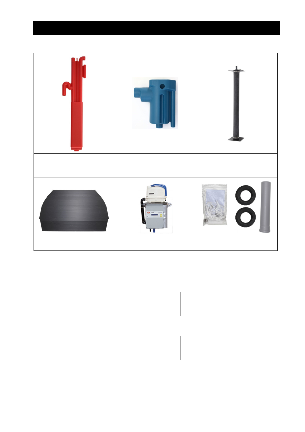
1. Scope of delivery
Jack Sampler 1 pipe aerator for 3 and 5
1. Scope of delivery
inhabitants
2 pipe aerators for 7 and 9
inhabitants
Scum board Control (one2clean plus control
without illustration)
The following is not included in the scope of delivery:
• Hoses to supply air from the control cabinet to the septic tanks. One 13 mm air hose and one 19
mm air hose are required.
They can be ordered under the following item numbers:
Hose package, 10 metres 107686
Hose package, 20 metres 107688
The hose packages each contain one 13 mm air hose and one 19 mm air hose. Alternatively, the
hoses can be ordered as rolled goods:
PVC hose, 20 metres, black, 13 x 3 mm 934017
PVC hose, 20 meters, blue, 19 x 3 mm 934020
• Core drill with a diameter of 124 mm. This can be purchased from Otto Graf GmbH using item
number 202003.
• The Carat S septic tank and covers are to be ordered separately.
Accessories
13 / 33
Page 3
2. Notes
2. Notes
2.1 Safety
Observe the national accident prevention regulations during all work. Particularly for inspecting the tanks,
a second person is required for safety reasons.
Furthermore, observe the valid national regulations and standards during installation, assembly, maintenance and repair work, etc.
During all work on the system or parts thereof, always shut down the entire system and secure it against
unauthorised re-start.
Always keep the tank cover closed, except when working in the tank. Otherwise, there is a high risk of an
accident occurring. Only genuine GRAF covers or covers that GRAF has approved in writing must be
used.
GRAF offers an extensive range of accessories, which are all coordinated to one another and can be
expanded to form complete systems. The use of accessories that have not been approved by GRAF results in the exclusion of the warranty/guarantee.
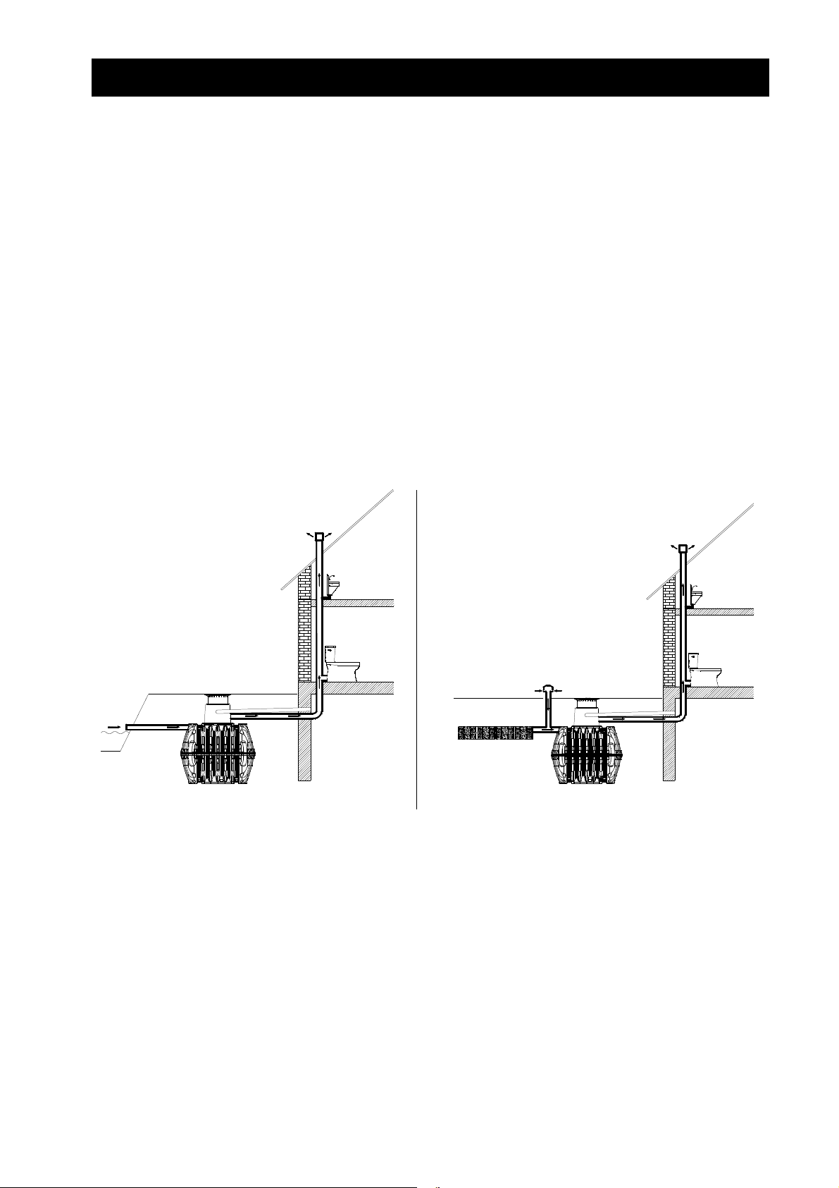
2.2 Ventilation and bleeding
All tanks must be ventilated and bled. Additional ventilation lines or ventilation openings must be ordered
if necessary. Ventilation lines should be ordered to guarantee natural ventilation (chimney effect).
Bleeding with a free outflow Bleeding with percolation or an obstructed outflow
14 / 33
Page 4
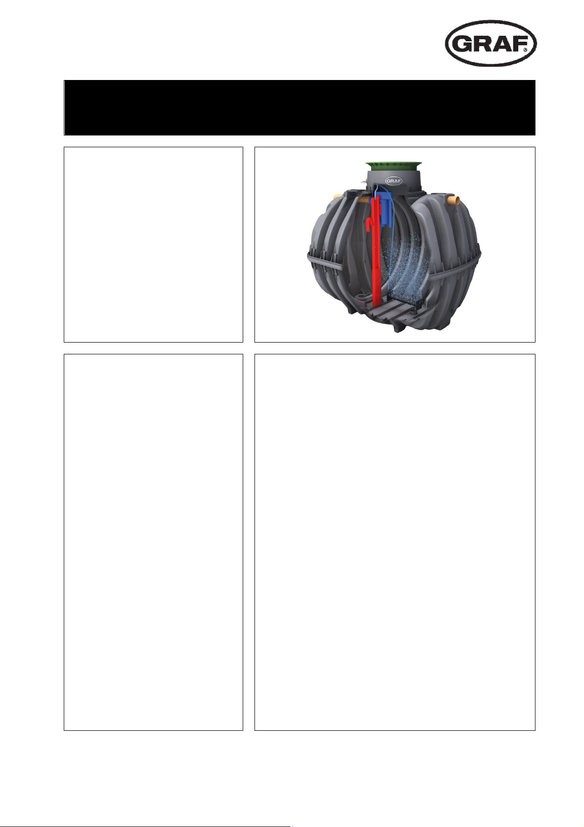
3. Construction and functional principle
3. Construction and functional principle
The small wastewater treatment system is fully biological and works according to the retention process
with long-term aeration. The system is made up of an aerobic stage. A scum board is used to split this
stage into a coarse substance chamber and an activation chamber. The chambers are connected to one
another in the bottom section. During this process, therefore, all domestic sewage is immediately exposed
to aerobic wastewater treatment. The entire system is aerated due to compressed air being blown in and
the sludge activated as a result of this biologically cleans the wastewater.
15 / 33
Page 5

4. Assembling the set-up kit
4. Assembling the set-up kit
1. 2.
Unfold the scum board. Place the clamps on either side of the folding edges.
Insert the scum board into the upper shell. A
groove offsets in an off-centre position.
3. 4.
>4cm
The fixing clamp has to be pushed with the
rounded stick in to the baffles side. The fixing
clamp has to be fixed.
Once the baffle has been positioned perforate the
inner rib directly above the wall using an 8mm. drill
head.
Perforate the baffle 4 cm. from its edge using the
same 8 mm. drill head.
5. 6.
Pass a cable tie through both holes and tighten it.
Cut the excess cable tie.
Repeat this procedure on the opposite side
Continue assembling the Carat RS tank according
to the installation instructions (seal, centring pins,
lubricant).
16 / 33
Page 6

4. Assembling the set-up kit
H
7. 8.
Place the upper shell with the scum wall on top of
the lower shell. Assemble the clamps for connecting the upper and lower shells.
Assemble the clamps for connecting the upper and
lower shells.
9. 10.
H
2700 L 3750 L 4800 L 6500 L
145 mm 145 mm 190 mm 205 mm
Drill the inflow and outflow with a DN 100 core
drill (with a diameter of 124 mm).
11.
De-burr the hole. Insert the DN 100 lip seal. In the
case of the outflow, the direction of the feedthrough must be from the inside out. Affix the “Outflow” sticker.
12.
Slide the outflow pipe through the outflow hole
from the inside.
The jack base must be turned depending on the
tank size. The specified tank size on the base must
be the same as on the jack.
17 / 33
Page 7

4. Assembling the set-up kit
2700 4800 6500
13.
Depending on the tank size, the length of the jack
must be adjusted by moving the jack base. The
rough position is specified on the jack. The exact
height is to be determined inside the tank.
15.
14.
Assemble the jack and sampler. To do this, push
the jack outflow into the sampler hole.
16.
-
Push the jack into the sampler (until it snaps into
place).
17.
Insert the jack into the profile for holding the partition wall from above.
Insert the jack into the tank along with the sampler.
18.
Insert the sampler’s outflow connection into the
sleeve of the outflow pipe (use lubricant!). The
sleeve connection must be secured with a Spax
screw.
18 / 33
Page 8

4. Assembling the set-up kit
6 mm hole
19.
The cord must be secured to the pipe aerator (6
mm hole). The air hose (19 mm) must be connected on the opposite side. Systems for more
than 7 inhabitants have two pipe aerators.
21.
20.
Position the pipe aerator(s) on the bottom of the
tank. It must be slid under the scum board such that
even the first chamber is ventilated. To attach the
cord, a hook is fitted inside the tank dome. The hole
for the hook should be pre-drilled with a 4mm bit.
22.
In systems with two pipe aerators, use a Ypiece to join the hoses of the two pipe aerators.
Assemble the tank dome according to the installation
instructions (seal!).
23. 24.
Secure the sampling tank to the tank dome with
a Spax screw.
Connect the air hose (13 mm) to the in-feed jack.
19 / 33
Page 9

5. Assembling control unit one2clean in the interior
5. Assembling control unit one2clean in the interior
1. 2.
The control must be installed in a dry and dustfree interior. Two 8 mm holes must be drilled
into the wall for assembly.
Secure the control to the wall using the dowels and
screws provided.
3. 4.
Position the compressor on the control. Connect
the compressor to the control unit pipe using the
90 Deg hose piece and hose clamps provided.
Plug the compressor plug into the control socket.
Connect the air hoses to the control’s hose nozzles.
5.
For further information please refer to the Control Unit operating manual.
Note for one2clean plus control: Assembly of one2clean plus control similar to one2clean control.
20 / 33
Page 10

6. Assembling control unit in the external cabinet
6. Assembling control unit in the external cabinet
1. 2.
Please refer to the installation instructions for
the External Cabinet for electrical connection
details.
Before installing the control unit, a strip of foam rubber
must be glued to the back of the control unit.
3. 4.
The Control Unit should be mounted to the
external cabinet with the screws and wing
nuts provided.
Position the compressor on top of the Control Unit and
connect together using the 90 Deg hose piece and
hose clamps provided.
5.
For further information please refer to the
Control Unit operating manual.
21 / 33
Page 11

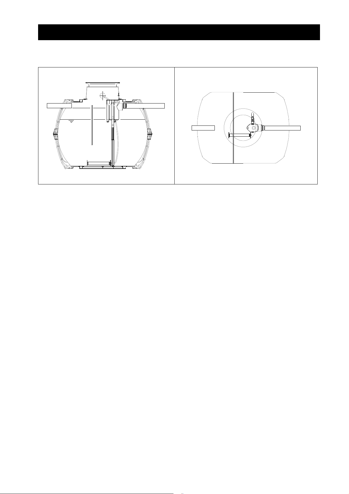
7. Technical data
tot
140-340
Z1
DN100
A
625
7. Technical data
A1
DN 100
Htot
Z2
L
nks 2,700 l 3,750 l 4,800 l 6,500 l
Ta
A2
L
Inhabitants 1-3 inhabitants 4-5 inhabitants 6-7 inhabitants 8-9 inhabitants
Max. daily inflow
0,45 m3/d 0,75 m3/d 1,05 m3/d 1,35 m3/d
Length L 2,080 mm 2,280 mm 2,280 mm 2,390 mm
Width B 1,565 mm 1,755 mm 1,985 mm 2,190 mm
Height H
1,690 / 2,010* mm 1,870 / 2,200* mm 2,100 / 2,430* mm 2,380 / 2,710* mm
Inflow Z1 430 / 750* mm 430 / 750* mm 515 / 835* mm 535 / 855* mm
Inflow Z2 1260 mm 1450 mm 1595 mm 1855 mm
Outflow A1 470 / 800* mm 470 / 800* mm 470 / 800* mm 470 / 800* mm
Outflow A2 1255 mm 1445 mm 1590 mm 1850 mm
* with Maxi tank dome
B
22 / 33
www.graf.info
06-2018
 Loading...