

Page 1
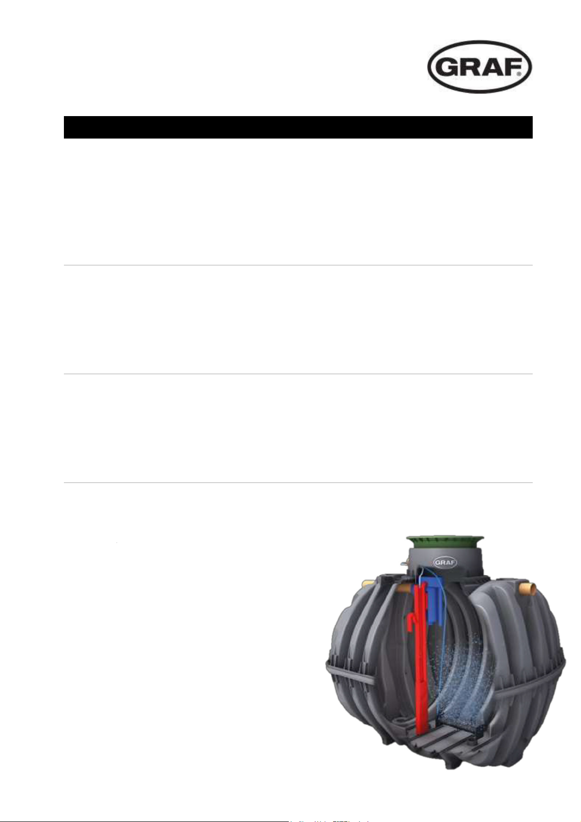
one2clean / one2clean plus
DE
EN
ES
one2clean / one2clean plus
Mehrbehälteranlage Einbauanleitung
>> Seite 1-12
one2clean / one2clean plus
Multi-Tank system installation instructions
>> Page 13-24
one2clean / one2clean plus
Instalación de varios depósitos instrucciones de instalación
>> Page 25-36
Page 2
one2clean / one2clean plus Mehrbehälteranlage
one2clean
Art.-Nr.
106854 Rüstsatz 7 EW
106855 Rüstsatz 10 EW
106856 Rüstsatz 14 EW
106857 Rüstsatz 18 EW
one2clean plus
Art.-Nr.
106425 / 106421 Rüstsatz 7 EW
106426 / 106422 Rüstsatz 10 EW
106427 / 106423 Rüstsatz 14 EW
106428 / 106424 Rüstsatz 18 EW
mail@graf.info
www.graf.info
Einbauanleitung
Die in dieser Anleitung beschriebenen Punkte sind unbedingt zu
beachten. Bei Nichtbeachtung erlischt jeglicher Garantieanspruch.
Für alle über GRAF bezogenen
Zusatzartikel erhalten Sie separate
in der Transportverpackung beiliegende Einbauanleitungen.
Eine Überprüfung der Bauteile auf
eventuelle Beschädigungen hat
unbedingt vor dem Versetzen in
die Baugrube zu erfolgen.
Für Betrieb und Wartung der Anlage erhalten sie eine separate Anleitung.
Inhaltsübersicht
1. LIEFERUMFANG 2
2. HINWEISE 3
2.1 Sicherheit 3
2.2 Be- und Entlüftung 3
3. AUFBAU UND FUNKTIONSPRINZIP 4
4. MONTAGE DES RÜSTSATZES 5
Bohren der Behälterhalbschalten 5
4.1
4.2 Montage 1. Behälter 5
4.3 Montage 2. Behälter 7
5. MONTAGE DER STEUERUNG IM INNENRAUM 10
6. MONTAGE DER STEUERUNG IM
AUßENSCHALTSCHRANK 11
7. TECHNISCHE DATEN 12
Page 3
1. Lieferumfang
1. Lieferumfang
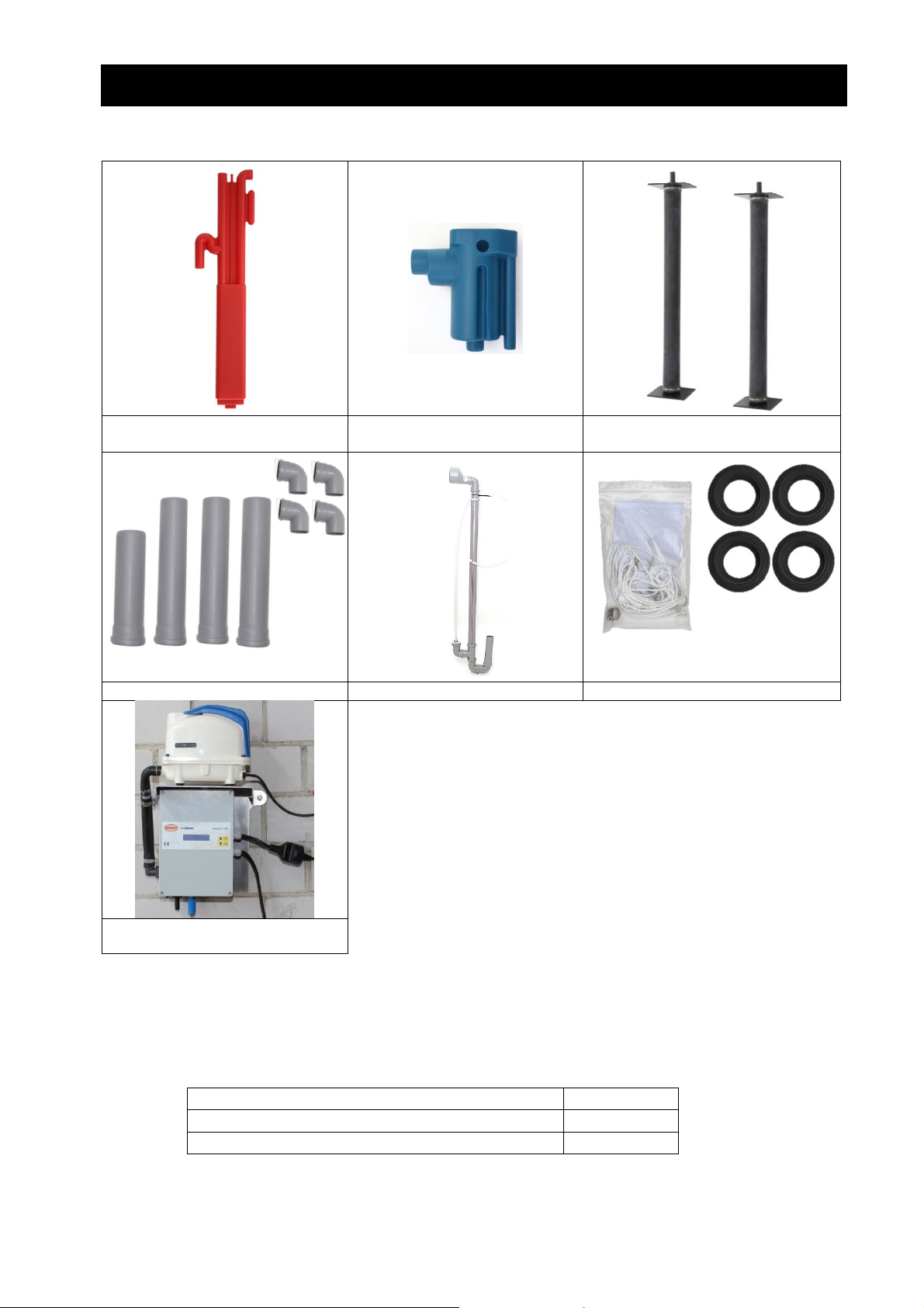
Heber Probeentnahme
Rohre Überschussschlammheber Zubehör
2 Rohrbelüfter für 7 und 10 EW,
4 Rohrbelüfter für 14 und 18 EW
Steuerung (Steuerung one2clean
plus ohne Abbildung)
Nicht im Lieferumfang enthalten sind:
• Schläuche zur Luftzufuhr vom Schaltschrank zu den Klärbehältern. Benötigt werden Luftschläuche 2 x 13 mm, 2 x 19 mm.
Die Schläuche können als Rollenware bestellt werden:
PVC-Schlauch 20 Meter, schwarz 13x3 mm 934017
PVC-Schlauch 20 Meter, blau 19x3 mm 934020
PVC-Schlauch 20 Meter, transparent 19x3 mm 934011
• Kronenbohrer Ø 124 mm. Dieser kann bei der Otto Graf GmbH mit der Artikelnummer 202003
bezogen werden.
• Klärbehälter Carat S und Abdeckungen sind separat zu bestellen.
2 / 36
Page 4
2. Hinweise
2. Hinweise
2.1 Sicherheit
Bei sämtlichen Arbeiten sind die nationalen Unfallverhütungsvorschriften zu beachten. Besonders bei
Begehung der Behälter ist eine 2. Person zur Absicherung erforderlich.
Des Weiteren sind bei Einbau, Montage, Wartung, Reparatur usw. die geltenden nationalen Vorschriften
und Normen zu berücksichtigen.
Bei sämtlichen Arbeiten an der Anlage bzw. Anlagenteilen ist immer die Gesamtanlage außer Betrieb zu
setzen und gegen unbefugtes Wiedereinschalten zu sichern.
Der Behälterdeckel ist stets, außer bei Arbeiten im Behälter, verschlossen zu halten, ansonsten besteht
höchste Unfallgefahr. Es sind nur Original GRAF-Abdeckungen oder von GRAF schriftlich freigegebene
Abdeckungen zu verwenden.
GRAF bietet ein umfangreiches Sortiment an Zubehörteilen, die alle aufeinander abgestimmt sind und zu
kompletten Systemen ausgebaut werden können. Die Verwendung, nicht von GRAF freigegebener Zubehörteile führt zu einem Ausschluss der Gewährleistung/Garantie.
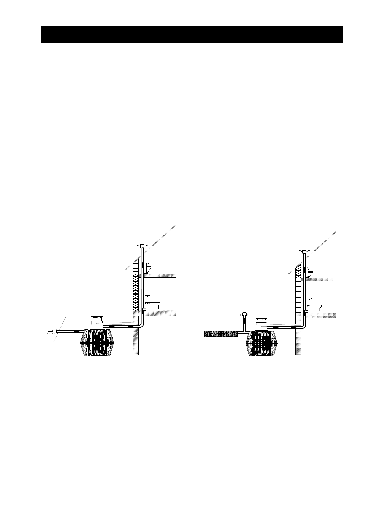
2.2 Be- und Entlüftung
Alle Behälter sind zu Be- und Entlüften. Falls erforderlich, sind zusätzliche Lüftungsleitungen oder Lüftungsöffnungen anzuordnen. Dabei sollten Lüftungsleitungen so angeordnet sein, dass eine natürliche
Lüftung möglich ist (Kaminwirkung).
Entlüftung bei freien Ablauf Entlüftung bei Versickerung oder nicht freiem Ablauf
3 / 36
Page 5
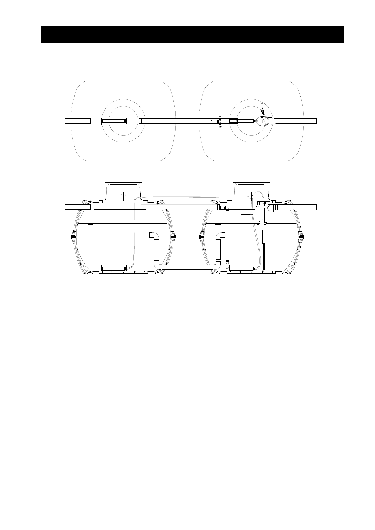
3. Aufbau und Funktionsprinzip
3. Aufbau und Funktionsprinzip
A
D
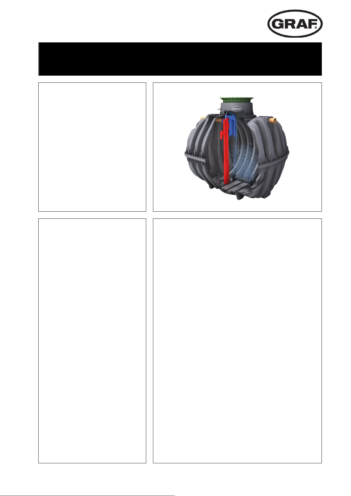
ie Kleinkläranlage ist eine vollbiologische Kleinkläranlage und arbeitet nach dem Aufstauverfahren mit
Langzeitbelüftung. Die Anlage besteht aus einer aeroben Stufe die in zwei Behälter aufgeteilt ist. Die
beiden Behälter sind im unteren Bereich miteinander verbunden, so dass stets derselbe Wasserstand in
beiden Behältern ist. Bei diesem Verfahren wird somit das gesamte häusliche Abwasser unmittelbar einer
aeroben Abwasserbehandlung ausgesetzt. Durch das Einblasen von Druckluft wird die gesamte Anlage
belüftet und der dadurch entstehende belebte Schlamm reinigt das Abwasser biologisch.
4 / 36
Page 6
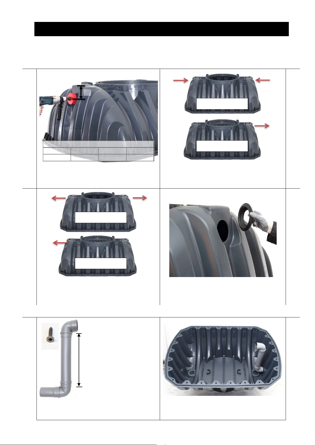
4. Montage des Rüstsatzes
6500 L H= 900 mm
H
4. Montage des Rüstsatzes
4.1 Bohren der Behälterhalbschalten
1. 2.
1. Behälter Oberschale
H
2700 L 3750 L 4800 L 6500 L
145 mm 145 mm 190 mm 205 mm
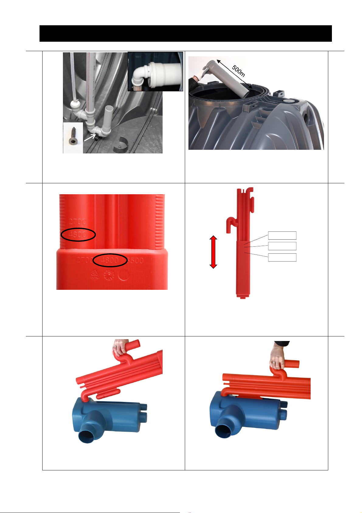
Die Zu-, Ablauf und Verbindungsleitungen an den
Halbschalen mit einem Kronenbohrer DN 100
bohren (Ø 124 mm).
Am 1. Behälter werden die Zu- und Ablaufleitungen
gemäß der oberen Abbildung gebohrt. Die Pfeilrichtung gibt die Durchführungsrichtung des Roh-
1. Behälter Unterschale
res an.
3. 4.
2. Behälter Oberschale
2. Behälter Unterschale
Am 2. Behälter werden die Zu- und Ablaufleitungen gemäß der oberen Abbildung gebohrt. Die
Pfeilrichtung gibt die Durchführungsrichtung des
Rohres an.
Bohrung entgraten. Lippendichtung DN 100 einsetzen. Die Durchführungsrichtung ist der vorherigen Abbildung zu entnehmen.
4.2 Montage 1. Behälter
5. 6.
Die untere Überlaufschikane zwischen den Behältern ist zusammenzusetzen. Muffen-Verbindungen sind mit Spax-Schrauben zu sichern.
H
2700 L H= 400 mm
3750 L H= 500 mm
4800 L H= 750 mm
Überlaufschikane in die Behälterunterschale einsetzen.
5 / 36
Page 7
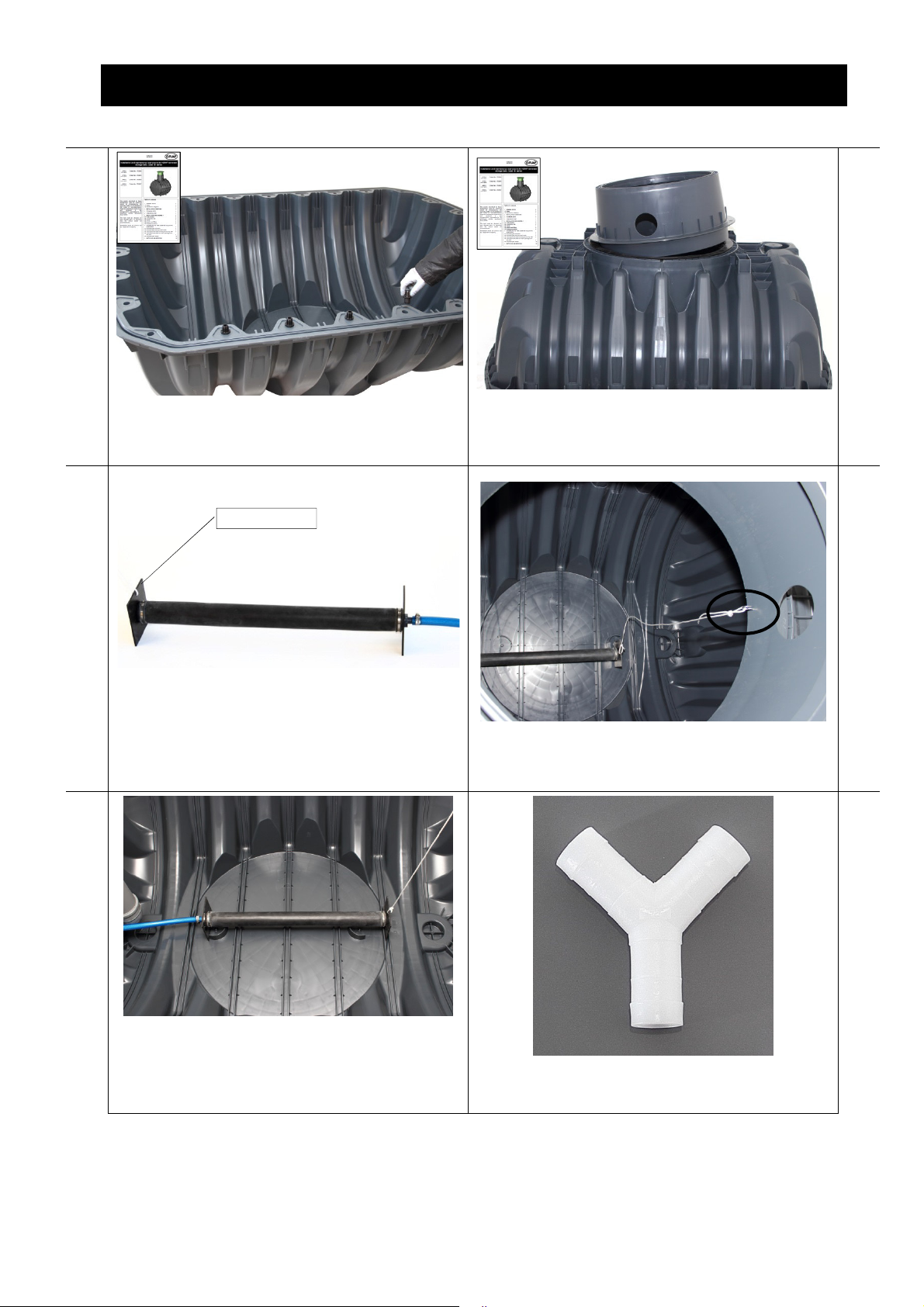
4. Montage des Rüstsatzes
Bohrung 6
mm
7. 8.
Den Carat S Tank gemäß Einbauanleitung zusammenbauen (Dichtung, Zentrierstifte, Klam-
Tankdom nach Einbauanleitung montierten
(Dichtung!).
mern, Oberschale aufsetzen)
9. 10.
An den Rohrbelüfter muss eine Schnur befestigt
werden (Bohrung 6mm). An der Gegenseite ist
der Luftschlauch (19mm) anzuschließen.
Für die Befestigung der Schnur wird im Tankdom
ein Hacken montiert. Das Loch für den Hacken ist
mit 4mm Bohrer vorzubohren.
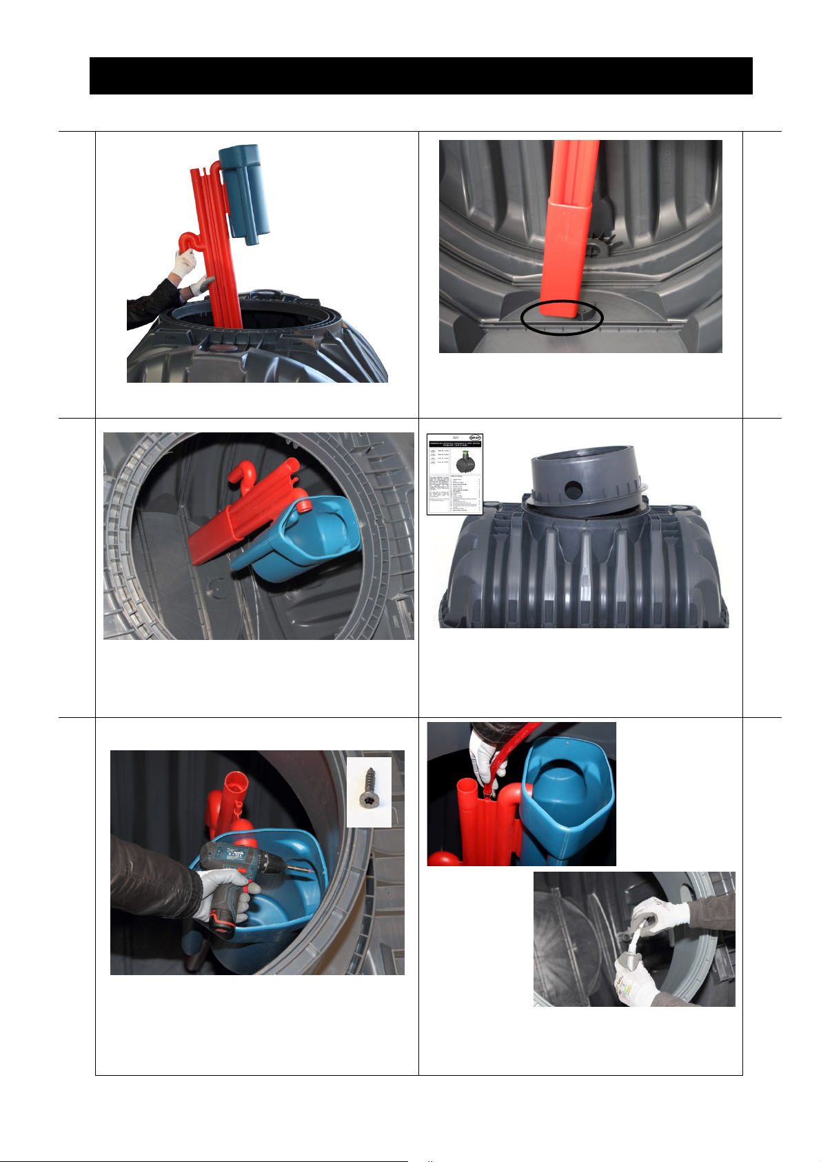
11.
Der/Die Rohrbelüfter werden am Behälterboden
positioniert. Zur Befestigung der Schnur wird der
Hacken am Teleskopdomschacht angebracht.
Bei Anlagen mit vier Rohrbelüftern werden die
Schläuche von jeweils zwei Rohrbelüftern mit einem Y-Stück zusammengeführt.
6 / 36
Page 8
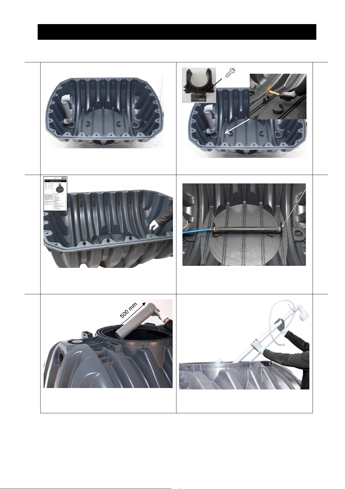
4.3 Montage 2. Behälter
4. Montage des Rüstsatzes
13.
Überlaufschikane wie im 1. Behälter einbauen. Die Halteklammer auf der letzten Boden Rippe
mittig montieren.
15.
14.
16.
Den Carat RS Tank gemäß Einbauanleitung zusammenbauen (Dichtung, Zentrierstifte, Klammern, Oberschale aufsetzen)
17.
Rohr für die Schlammrückführung von innen durch
die Bohrung für die Schlammrückführung schieben.
Rohrbelüfter wie im ersten Behälter montieren. Zur
Befestigung der Schnur wird der Hacken am Teleskopdomschacht angebracht.
18.
Die Schlammrückführung in den Tank einsetzen.
7 / 36
Page 9
4. Montage des Rüstsatzes
2700
4800 6500
19.
Schlammrückführung in Halteklammer stecken
und mit Spax-Schraube zusätzlich sichern. Oben
im Tank die Schlammrückführung in das Rohr für
die Schlammrückführung stecken.
21.
20.
Ablaufrohr von innen durch die Auslaufbohrung
schieben.
22.
Je nach Tankgröße muss der Heberschuh gedreht
werden. Die angegebene Behältergröße auf dem
Fußteil muss mit der auf dem Heber übereinstimmen.
23.
Heber und Probeentnahme zusammensetzen.
Dazu den Auslauf des Hebers in die Bohrung der
Probeentnahme drücken.
Die Länge des Hebers muss je nach Tankgröße
durch verschieben des Heberschuhs angepasst
werden. Die ungefähre Position ist auf dem Heber
angegeben. Die exakte Höhe ist im Behälter zu
bestimmen.
24.
Heber in die Probeentnahme drücken (bis zum
Einrasten)
8 / 36
Page 10
4. Montage des Rüstsatzes
25.
Heber mit Probeentnahme in den Tank einsetzen. Der Heber wird von oben in das Profil zur Trenn-
wandaufnahme gesteckt.
27.
26.
28.
Der Auslaufstutzen der Probeentnahme wird in die
Muffe des Auslaufrohres gesteckt (Gleitmittel verwenden!). Die Muffen-Verbindung ist mit einer
Spax-Schraube zu sichern.
29.
Probeentnahmebehälter mit Spax-Schraube am
Tankdom befestigen
Der Tankdom wird nach Einbauanleitung montiert
(Dichtung!).
30.
Luftschlauch (13mm) am Heber für den Klarwasserabzug anschließen. Luftschlauch (13mm) am
Heber für die Schlammrückführung anschließen.
9 / 36
Page 11
5. Montage der Steuerung one2clean im Innenraum
5. Montage der Steuerung one2clean im Innenraum
1. 2.
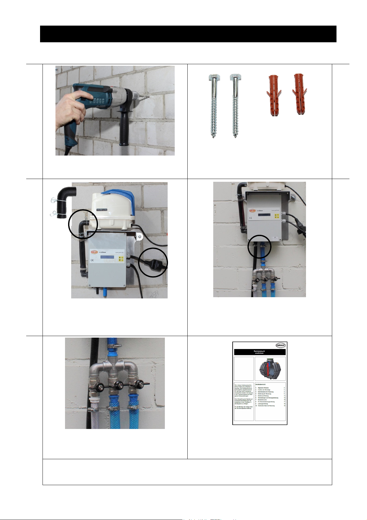
Die Steuerung ist in einem trockenen und staubfreien Innenraum zu installieren. Zur Montage sind
zwei Bohrungen 8 mm in die Wand zu bohren.
Die Steuerung wird mit den mitgelieferten Dübeln
und Schrauben an der Wand befestigt.
3. 4.
Der Verdichter wird auf die Steuerung gestellt.
Zum Luftanschluss ist der Gummi-Winkel zu verwenden. Der Stecker des Verdichters wird in die
Buchse der Steuerung gesteckt.
Die Schlauch für den Klarwasserabzug (1/2“) wird
direkt an die schwarze Schlauchtülle an der Steuerung angeschlossen. An die blaue Schlauchtülle
der Steuerung (3/4“) wird der Zusätzliche Luftverteiler angeschlossen.
5.
An die zwei 3/4“ Schlauchtüllen werden die
Schläuche für die Belüftung angeschlossen. An
den 1/2“ Anschluss wird der Schlauch für die
Schlammrückführung angeschlossen.
Hinweis one2clean plus Steuerung: Die Montage der one2clean plus Steuerung erfolgt analog zur one2clean
Steuerung. Die one2clean plus Steuerung besitzt ein drittes Ventil zur Schlammrückführung. Daher wird der Luftverteiler mit den Ventilen nicht benötigt.
Die weitere Inbetriebnahme der Kläranlage und
Einstellung der Steuerung ist im Betriebsbuch
beschrieben.
10 / 36
Page 12
6. Montage der Steuerung im Außenschaltschrank
6. Montage der Steuerung im Außenschaltschrank
1. 2.
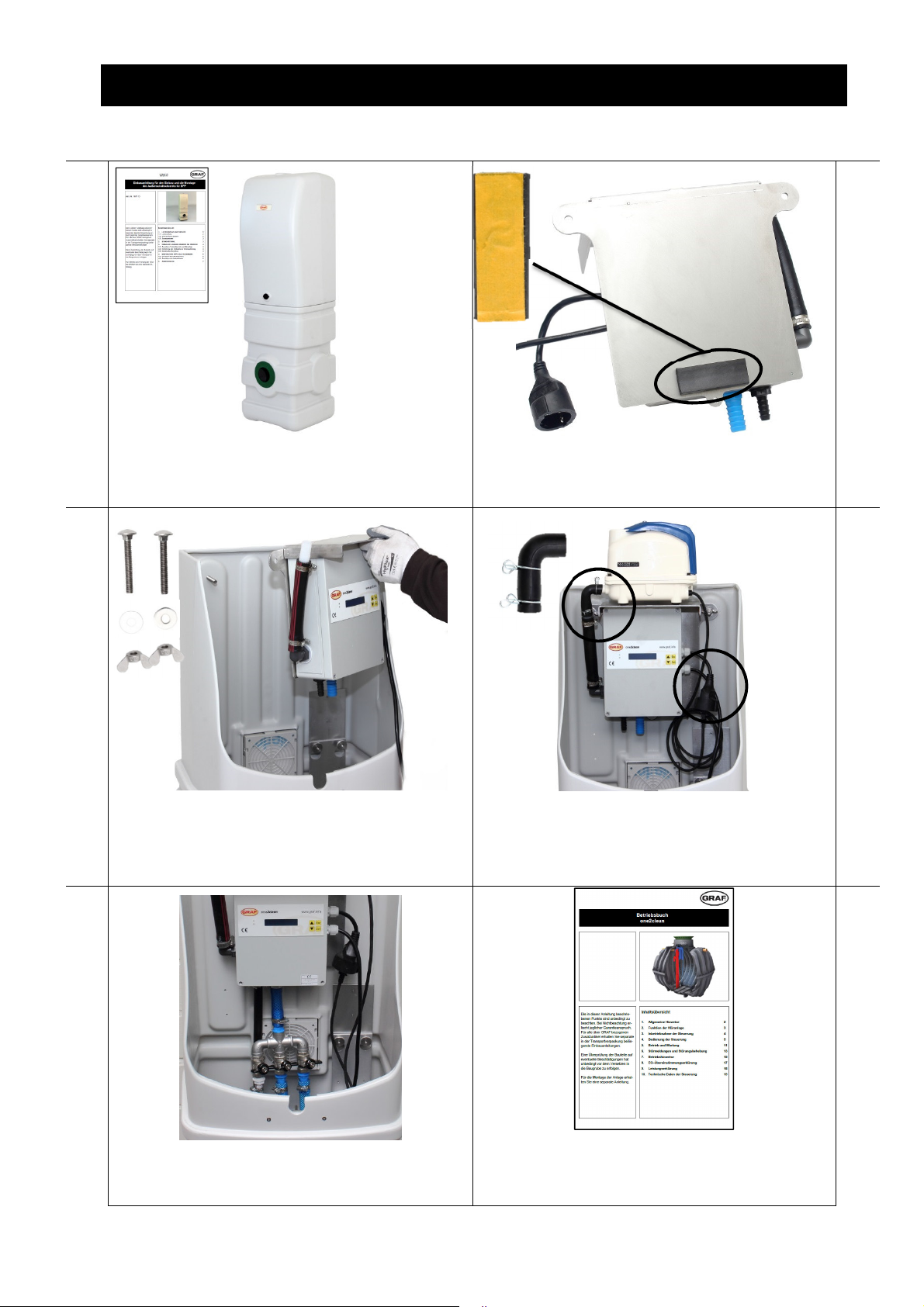
Der Außenschaltschrank ist nach Einbauanleitung
aufzustellen und der elektrische Anschluss ist zu
erstellen.
Vor Montage der Steuerung ist auf der Rückseite
der Steuerung ein Streifen Moosgummi zu kleben.
3. 4.
Die Steuerung wird mit den Schrauben und Flügelmuttern, die dem Schaltschrank beiliegen, befestigt.
Der Verdichter wird auf die Steuerung gestellt.
Zum Luftanschluss ist der Gummi-Winkel zu verwenden. Zum Stromanschluss wird der Stecker
des Verdichters in die Buchse der Steuerung gesteckt.
5.
Die Montage des zusätzlichen Luftverteiler verläuft
analog zu 5.4 und 5.5.
11 / 36
Die weitere Inbetriebnahme der Kläranlage und
Einstellung der Steuerung ist im Betriebsbuch
beschrieben.
Page 13

7. Technische Daten
B
140-340
7. Technische Daten
L L
Z1
A
Htot
Z2
DN 100
Tanks 2 x 2700 L 2 x 3750 L 2 x 4800 L 2 x 6500 L
Einwohner 2-7 EW 8-10 EW 11-14 EW 15-18 EW
max. Tageszufluss
Länge
Breite
Höhe
Einlauf E
Ablauf A
1,05 m
3
/d 1,50 m3/d
2,10 m3/d
2080 mm 2280 mm 2280 mm 2390 mm
1565 mm 1755 mm 1985 mm 2190 mm
1690 / 2010* mm 1870 / 2200* mm 2100 / 2430* mm 2380 / 2710* mm
200 / 520* mm 200 / 520* mm 200 / 520* mm 200 / 520* mm
470 / 800* mm 470 / 800* mm 470 / 800* mm 470 / 800* mm
2,7 m
3
/d
* mit Tankdom Maxi
DN100DN100
A2
A1
12 / 36
www.graf.info
06-2018
Page 14

one2clean / one2clean plus Multi-Tank System
Installation instructions
one2clean
Item no.
106854 Installation kit 7 PE
106855 Installation kit 10 PE
106856 Installation kit 14 PE
106857 Installation kit 18 PE
one2clean plus
Item no.
106425 / 106421 Installation kit 7 PE
106426 / 106422 Installation kit 10 PE
106427 / 106423 Installation kit 14 PE
106428 / 106424 Installation kit 18 PE
mail@graf.info
www.graf.info
The points described in these instructions must be observed in all
cases. Failure to do so shall invalidate the warranty. For any additional items purchased through
GRAF, you will receive separate
installation instructions in the
transport packaging.
The components must be checked
for any damage before the system
is transferred to the pit.
You will receive separate instructions for operation and maintenance of the system.
Contents
1. SCOPE OF SUPPLY
2. PLEASE NOTE:
2.1 Safety
2.2 Ventilation
3. INSTALLATION AND OPERATING PRINCIPLE
4. FITTING THE INSTALLATION KIT
4.1 Drilling the tank shells
4.2 Assembly of first tank
4.3 Assembly of second tank
5. INSTALLING THE CONTROL UNIT INDOORS
6. INSTALLING THE CONTROL UNIT IN AN EXTERNAL
CONTROL CABINET
7. TECHNICAL DATA
14
15
15
15
16
17
17
17
19
22
23
24
Page 15

1. Scope of supply
1. Scope of supply
Lifter Sampling unit
Pipes
Excess sludge lifter
2 pipe aerators for 7 and 10 PE,
4 pipe aerators for 14 and 18 PE
Accessories
Control unit (one2clean plus control
without illustration)
The following items are not included in the shipment:
• Hoses to supply air from the switch cabinet to the septic tanks. Air hoses (2 x 13 mm, 2 x 19 mm)
are needed.
The hoses can be ordered by the reel:
20-metre PVC hose, black, 13 x 3 mm 934017
20-metre PVC hose, blue, 19 x 3 mm 934020
20-metre PVC hose, transparent, 13 x 3 mm 934011
• Core drill Ø 124 mm. This can be purchased from Otto Graf GmbH using article number 202003.
• Carat S septic tank and covers must be ordered separately.
14 / 36
Page 16

2. Please note:
2. Please note:
2.1 Safety
All work should be undertaken in compliance with national accident prevention regulations. A second
person is required for safety reasons, particularly when inspecting tanks.
In addition, the applicable national regulations and standards must be respected during installation, assembly, maintenance, repairs etc.
The entire system must always be switched off and secured against unauthorised resetting during any
work on the system or system components.
The tank cover must always be kept closed, except during work inside the tank, otherwise the risk of accidents is high. Only original GRAF covers, or covers approved by GRAF in writing, are to be used.
GRAF provides an extensive range of accessories, which are all coordinated and can be combined to
form complete systems. The use of accessories that have not been approved by GRAF results in the exclusion of the warranty/guarantee.
2.2 Ventilation
All tanks must be ventilated. Additional ventilation ducts or openings are to be arranged if required. If this
occurs, the ventilation ducts should be arranged so that natural ventilation is possible (chimney effect).
Ventilation with unobstructed outflow Ventilation in the case of infiltration or with obstructed
outflow
15 / 36
Page 17

3. Installation and operating principle
3. Installation and operating principle
A
T
he system is a fully biological small wastewater treatment system and functions on the principle of the
retention process with extended aeration. The system consists of an aerobic stage split into two tanks.
The two tanks are connected in the lower area so that the water level is always the same in both tanks.
This process therefore subjects all the domestic wastewater directly to aerobic wastewater treatment.
Blowing in compressed air aerates the entire system and the sludge aerated by this biologically cleans
the wastewater.
16 / 36
Page 18

4. Fitting the installation kit
6500 L H= 900 mm
H
4. Fitting the installation kit
4.1 Drilling the tank shells
1. 2.
Tank 1 upper shell
H
2700 L 3750 L 4800 L 6500 L
145 mm 145 mm 190 mm 205 mm
Drill holes for the inlet, outlet and connecting lines
on the shells using a DN 100 core drill (diameter
124 mm).
On the first tank, the holes for the inlet and outlet
lines are drilled as shown above. The arrows indicate the direction in which the pipe is fed through.
Tank 1 lower shell
3. 4.
Tank 2 upper shell
Tank 2 lower shell
On the second tank, the holes for the inlet and
outlet lines are drilled as shown above. The arrows indicate the direction in which the pipe is fed
through.
Deburr hole. Insert DN 100 edge seal. The feedthrough direction can be seen in the previous diagram.
4.2 Assembly of first tank
5. 6.
Assemble the lower overflow baffle between the
tanks. The socket connections must be secured
using Spax screws.
H
2700 L H= 400 mm
3750 L H= 500 mm
4800 L H= 750 mm
Insert overflow baffle in lower shell.
17 / 36
Page 19

4. Fitting the installation kit
6 mm hole
7. 8.
Assemble the Carat S tank as described in the
installation instructions (seal, centring pins, clips,
position upper shell)
Fit the tank dome as described in the installation
instructions (seal!).
9. 10.
A cord must be attached to the pipe aerator (6mm
hole). The air hose (19mm) is connected on the
opposite side.
To attach the cord, a hook is fitted inside the tank
dome. The hole for the hook should be pre-drilled
with a 4mm bit.
11.
The pipe aerator(s) are positioned on the tank
base. To attach the cord, the hook is fastened to
the telescopic dome shaft.
In systems with four pipe aerators, the hoses are
joined in pairs with a Y-piece.
18 / 36
Page 20

4.3 Assembly of second tank
4. Fitting the installation kit
13.
Install overflow baffle as in first tank. Fit the retaining clips centrally on the last base rib.
15.
14.
16.
Assemble the Carat RS tank as described in the
installation instructions (seal, centring pins, clips,
position upper shell).
17.
Slide sludge return pipe from inside through the
hole for the sludge return.
Fit pipe aerator(s) as for the first tank. To attach
the cord, the hook is fastened to the telescopic
dome shaft.
18.
Insert sludge return into tank.
19 / 36
Page 21

4. Fitting the installation kit
2700
4800 6500
19.
Push sludge return into retaining clip and additionally secure with Spax screw. At the top of the
tank, push the sludge return into the sludge return
pipe.
21.
20.
Slide drain pipe through outlet hole from inside.
22.
Depending on tank size, the lifter shoe has to be
turned. The tank size stated on the foot section
must match that on the lifter.
23.
Assemble lifter and sampling unit by pressing
lifter's outlet into sampling unit's hole.
Depending on tank size, the lifter length must be
adapted by moving the lifter shoe. The approximate position is stated on the lifter. The exact
height should be determined in the tank.
24.
Press lifter into sampling unit (until it engages)
20 / 36
Page 22

4. Fitting the installation kit
25.
Insert lifter with sampling unit in tank. The lifter is placed from above to hold the dividing
wall.
27.
26.
28.
The sampling unit's outlet connector is placed into
the outlet pipe's socket (use lubricant!). The socket connection should be secured with a Spax
screw.
29.
Secure sampling tank to tank dome with Spax
screw.
The tank dome is fitted as described in the installation instructions (seal!).
30.
Connect air hose (13mm) to lifter for clear water
extraction. Connect air hose (13mm) to lifter for
sludge return.
21 / 36
Page 23

5. Installing the control one2clean unit indoors
5. Installing the control one2clean unit indoors
1. 2.
The control unit should be installed in a dry, dustfree indoor location. To install, drill two 8mm holes
in the wall.
The control unit is secured to the wall with the
dowels and screws supplied.
3. 4.
The compressor is placed on top of the control
unit. Use the rubber bracket for the air connection.
The compressor's connector is plugged into the
socket on the control unit.
The hose for clear water extraction (1/2") is directly connected to the black hose connector on the
control unit. The additional air distributor is connected to the control unit's blue hose connector
(3/4").
5.
The aeration hoses are connected to the two 3/4"
hose connectors. The sludge return hose is connected to the 1/2" connection.
Note one2clean plus control unit: The assembly of the one2clean plus control unit is to be carried out in the same
way as the one2clean control unit. The one2clean plus control unit is equipped with a third valve for the excess
sludge removal. Therefore the air distributor with the valves is not needed.
For information about starting up the wastewater
treatment system and setting the control unit, refer
to the operating logbook.
22 / 36
Page 24

6. Installing the control unit in an external control cabinet
6. Installing the control unit in an external control cabinet
1. 2.
Install the external control cabinet as described in
the installation instructions and establish the electrical connection.
Before installing the control unit, a strip of foam
rubber must be glued to the back of the control
unit.
3. 4.
The control unit is secured with the screws and
wing nuts supplied with the cabinet.
The compressor is placed on top of the control
unit. Use the rubber bracket for the air connection.
For the power connection, the compressor's connector is plugged into the socket on the control
unit.
5.
The additional air distributor is fitted as described
in 5.4 and 5.5.
For information about starting up the wastewater
treatment system and setting the control unit, refer
to the operating logbook.
23 / 36
Page 25

7. Technical data
tot
B
140-340
7. Technical data
L L
Z1
A
Htot
Z2
DN 100
Tanks 2 x 2,700 L 2 x 3,750 L 2 x 4,800 L 2 x 6,500 L
Inhabitants 2-7 PE 8-10 PE 11-14 PE 15-18 PE
Max. daily inflow
Length L
Width B
Height H
Inlet Z1
Inlet Z2
Outlet A1
Outlet A2
1.05 m
3
/d 1.50 m3/d
2.10 m3/d
2080 mm 2280 mm 2280 mm 2390 mm
1565 mm 1755 mm 1985 mm 2190 mm
1690 / 2010* mm 1870 / 2200* mm 2100 / 2430* mm 2380 / 2710* mm
430 / 750* mm 430 / 750* mm 515 / 835* mm 535 / 855* mm
1260 mm 1450 mm 1595 mm 1855 mm
470 / 800* mm 470 / 800* mm 470 / 800* mm 470 / 800* mm
1255 mm 1445 mm 1590 mm 1850 mm
2.7 m
3
/d
* with maxi tank dome
DN100DN100
A2
A1
24 / 36
www.graf.info
06-2018
Page 26

mail@graf.info
www.graf.info
one2clean / one2clean plus Instalación de varios depósitos
Instrucciones de instalacións
one2clean
Código
106854 Kit de instalación 7 HAB
106855 Kit de instalación 10 HAB
106856 Kit de instalación 14 HAB
106857 Kit de instalación 18 HAB
one2clean plus
Código
106425 / 106421 Kit de instalación 7 HAB
106426 / 106422 Kit de instalación 10 HAB
106427 / 106423 Kit de instalación 14 HAB
106428 / 106424 Kit de instalación 18 HAB
Los puntos descritos en estas
instrucciones deben ser
respetados obligatoriamente. En
caso de incumplimiento se
extingue todo derecho a garantía.
Recibirá adjuntas en el embalaje
de transporte por separado las
instrucciones de instalación para
todos los artículos adicionales
adquiridos a GRAF.
Antes de trasladar el producto a la
excavación examine sin falta los
componentes para detectar
eventuales desperfectos.
Le facilitamos una instrucción
separada para el manejo y
funcionamiento de la instalación.
Índice de contenido
1. VOLUMEN DE SUMINISTRO
2. INDICACIONES
2.1 Seguridad
2.2 Aireaciones
3. EXPLICACIÓN DEL PRINCIPIO DEL
FUNCIONAMIENTO
4. MONTAJE DEL KIT DE INSTALACIÓN
4.1 Perforación de las dos mitades del depósito
4.2 Montaje 1º Depósito
4.3 Montar el 2º Depósito
5. INSTALACIÓN DEL CUADRO DE CONTROL EN
INTERIOR
6. INSTALACIÓN DEL CUADRO DE CONTROL EN EL
ARMARIO DE DISTRIBUCIÓN EXTERIOR
7. DATOS TÉCNICOS
26
27
27
27
28
29
29
29
31
34
35
36
Page 27

1. Volumen de suministro
Sifón Toma de muestras
1. Volumen de suministro
2 Aireadores tubulares para 7 y 10
habitantes
4 Aireadores tubulares para 14 y
18 habitantes
Tubos de conexión Elevador de retorno de lodos Accesorios para la instalación
Cuadro de control (Foto no
disponible para la unidad de control
one2clean plus)
No incluido con el equipo:
• Mangueras para la conducción del aire desde el cuadro de control hasta los depósitos de la
depuradora. Se necesitan mangueras de aire 2 x 13 mm, 2 x 19 mm.
Las mangueras se pueden pedir en rollos:
Manguera de PVC de 20 metros, negra 13x3 mm 934017
Manguera de PVC de 20 metros, azul 19x3 mm 934020
Manguera de PVC de 20 metros, transparente 19x3 mm
Manguera de PVC de 20 metros, azul 19x3 mm
26 / 36
Page 28

2. Indicaciones
• Broca de corona Ø 124 mm. Esta broca de corona se puede adquirir a Otto Graf GmbH con el
código 202003.
• El depósito Carat S y las cubiertas se deben pedir por separado.
2. Indicaciones
2.1 Seguridad
Para todos los trabajos se deben observar las normativas nacionales sobre prevención de accidentes.
Particularmente, en la inspección personal de los depósitos se requiere una segunda persona para fines
de seguridad.
Aparte de esto se deben seguir las prescripciones y normas nacionales vigentes para la ejecución de los
trabajos de instalación, montaje, mantenimiento, reparación, etc.
Antes de realizar cualquier trabajo en el equipo o en piezas individuales del mismo debe ponerse todo el
equipo fuera de servicio, protegiéndolo al mismo tiempo contra una puesta en marcha no autorizada.
Excepto durante la realización de los trabajos necesarios en el depósito se deberá mantener siempre
cerrada la tapa del depósito. En caso contrario existe un alto riesgo de accidente. Sólo se deben utilizar
exclusivamente tapas originales de GRAF o tapas aprobadas por escrito por GRAF.
GRAF ofrece un amplio surtido de accesorios que han sido adaptados entre sí y que pueden ampliarse
para formar sistemas completos. El uso de accesorios no aprobados por GRAF da lugar a la pérdida de
la garantía legal/comercial.
2.2 Aireación y desaireación
Todos los depósitos deben tener una correcta aireación. Si resulta necesario hay que prever tuberías de
aireación adicionales. Las tuberías de aireación deben estar dispuestas de tal forma que se permita una
aireación natural (efecto chimenea).
Aireación con salida libre Aireación en caso de infiltración de agua al terreno o
conexión a alcantarillado.
27 / 36
Page 29

3. Explicación del funcionamiento
3. Explicación del funcionamiento
A
L
a depuradora One2clean es una depuradora completamente biológica mediante el principio SBR
(reactor discontinuo secuencial) con aireación permanente. La depuradora se compone de un equipo de
dos depósitos. Los dos depósitos están unidos en su parte inferior, de modo que el nivel de agua es
siempre el mismo en ambos depósitos. Con este método toda el agua residual es tratada directamente
con un tratamiento aeróbico. Inyectando aire desde el compresor se airean los dos depósitos y el lodo
activado, que contiene las bacterias, depura el agua residual biológicamente.
28 / 36
Page 30

4. Montaje del kit de instalación
6500 L H= 900 mm
H
4. Montaje del kit de instalación
4.1 Perforación de las dos mitades del depósito
1. 2.
1º depósito parte superior
H
2700 L 3750 L 4800 L 6500 L
145 mm 145 mm 190 mm 205 mm
1º depósito parte inferior
Con ayuda de una broca de corona DN 100 (Ø
124 mm) perforar los agujeros para la conexión
de las tuberías de entrada, salida y unión en las
dos mitades del depósito.
Perforar los agujeroos para las tuberías de entrada
y salida en el primer depósito de acuerdo con la
ilustración de arriba. El sentido de la flecha indica
el sentido del tubo.
3. 4.
2 depósito parte superior
2 depósito parte inferior
Perforar los agujeros para las tuberías de entrada
y salida en el 2 depósito según la ilustración de
arriba. El sentido de la flecha indica el sentido del
tubo.
4.2 Montaje 1º Depósito
Eliminar las rebabas de los agujeros realizados.
Colocar la junta DN 100. El sentido de la junta
debe coincidir con el sentido de la tubería.
5. 6.
Realizar la conexión inferior entre los depósitos.
Asegurar la conexión de las piezas con los
tornillos Spax incluidos.
A
2700 L H= 400 mm
3750 L H= 500 mm
4800 L H= 750 mm
Colocar la tubería de la conexión inferior en la
parte inferior del depósito.
29 / 36
Page 31

4. Montaje del kit de instalación
7. 8.
Ensamblar el depósito Carat S según la
instrucción de instalación (junta, clavijas
Cúpula montada según las instrucciones de
instalación (¡Atención a la colocación de la junta!).
centradoras, abrazaderas, colocar la parte
superior)
9. 10.
Agujero
perforado de 6
mm
Hay que atar una cuerda (incluida en el kit) en el
agujero perforado de 6mm en al aireador de
tubo. Conectar la manguera de aire (19 mm) en
Fijar el tornillo de gancho (incluido) en la cúpula
para sujetar la cuerda. El agujero para fijar el
tornillo se debe perforar con una broca de 4 mm.
el conector del lado opuesto.
11.
El/los aireador/es de tubo se deben posicionar en
el fondo del depósito. Fijar el tornillo para sujetar
la cuerda en la cupula.
En las depuradoras con cuatro aireadores
tubulares se deben juntar las mangueras de dos
aireadores de tubo, respectivamente con una pieza
en Y.
30 / 36
Page 32

4.3 Montar el 2 Depósito
4. Montaje del kit de instalación
13.
Colocar la tubería de la conexión inferior en la
parte inferior del depósito de la misma forma que
en el 1 depósito.
15.
14.
Fijar la abrazadera de sujección centrada en la
guia más cercana a la conexión entre depósitos.
16.
Ensamblar el depósito Carat RS según las
instrucciones de instalación (junta, pivotes
centradores y grapas)
17.
Insertar el tubo para la recirculación del lodo
desde dentro a través del agujero perforado para
el rerorno del lodo.
Colocar el aireador tubular de la misma forma que
en el 1 depósito. Fijar el tornillo para sujetar la
cuerda en la cupula.
18.
Colocar el elevador para la recirculación del lodo
en el depósito.
31 / 36
Page 33

4. Montaje del kit de instalación
2700 4800
6500
19.
Fijar el elevador de la recirculación del lodo en la
abrazadera de sujeción y asegurarlo
adicionalmente con un tornillo Spax. En la parte
superior del depósito se debe fijar la recirculación
del lodo en el tubo que va al primer depósito.
21.
20.
Insertar el tubo de salida desde dentro en el
agujero de salida.
22.
Según la capacidad del depósito hay que girar el
sifón. La capacidad del depósito indicado en el pie
del mismo debe coincidir con el tamaño indicado
en el sifón.
23.
Ensamblar el sifón y la toma de muestras. Para
este fin hay que insertar la salida del sifón en el
orificio perforado de la toma de muestras.
La longitud del sifón debe adaptarse según la
capacidad del depósito desplazando la parte
inferior del sifón. La posición aproximada viene
indicada en el sifón. La altura exacta debe
determinarse en el depósito.
24.
Insertar el sifón en la toma de muestras (hasta
que encaje)
32 / 36
Page 34

4. Montaje del kit de instalación
25.
Montar el sifón con la toma de muestras en el
depósito.
27.
26.
Insertar el sifón desde arriba en la guía de
alojamiento del depósito.
28.
Insertar el tubo de salida de la toma de muestras
en la tubería de salida (¡utilizar un lubricante!).
Asegurar la conexión con un tornillo Spax.
29.
Fijar la toma de muestras con el tornillo Spax en
la cúpula del depósito
Cúpula montada según las instrucciones de
instalación (¡Atención a la colocación de la junta!).
30.
Conectar la manguera de aire (13 mm) en el sifón
para la extracción de agua depurada. Conectar la
manguera de aire (13 mm) en el sifón para la
recirculación del lodo.
33 / 36
Page 35

5. Instalación del cuadro de control one2clean en interior
5. Instalación del cuadro de control one2clean en interior
1. 2.
Hay que instalar el cuadro de control en un
espacio interior limpio y libre de polvo. Para
realizar el montaje deben taladrarse dos agujeros
de 8mm en la pared.
Hay que sujetar el cuadro de control en la pared
con los tacos y tornillos incluidos con el equipo.
3. 4.
Colocar el compresor sobre el soporte de la parte
superior del cuadro de control. Utilizar el codo de
goma para la conexión de aire. Conectar el
enchufe del compresor en el conector hembra del
cuadro de control.
Conectar la manguera para la extracción de agua
depurada (1/ 2“) directamente en la boquilla negra
del cuadro de control. Conectar el distribuidor de
aire adicional en la boquilla azul del cuadro de
control (3/ 4“).
5.
Conectar las mangueras de aireación en las dos
boquillas de 3/ 4“. Conectar la manguera para la
recirculación del lodo en la conexión ½”.
Nota unidad de control one2clean plus: Para el armado de la unidad de control del one2clean plus deben seguirse
las mismas indicaciones que para el sistema one2clean. La unidad de control del one2clean plus dispone de una
tercera válvula que sirve para la recirculación de lodos; por este motivo no se requiere una válvula distribuidora de
aire.
La puesta en marcha de la depuradora y el ajuste
del control están descritos en el manual de
funcionamiento y puesta en marcha.
34 / 36
Page 36

6. Instalación del cuadro de control en el armario de distribución exterior
6. Instalación del cuadro de control en el armario de distribución exterior
1. 2.
El armario de distribución exterior se debe colocar
según las instrucciones de montaje y tenderse la
conexión eléctrica.
Antes del montaje del controlador debe pegarse
la goma anti vibración en la parte posterior del
mismo.
3. 4.
Hay que fijar el cuadro de control con los tornillos
y las tuercas de mariposa incluidos con el armario
de distribución.
Colocar el compresor sobre el soporte de la parte
superior del cuadro de control. Utilizar el codo de
goma para la conexión de aire. Conectar el
enchufe del compresor en el conector hembra del
cuadro de control.
5.
La instalación del distribuidor de aire adicional
debe realizarse de la misma forma descrita en los
puntos 5.4 y 5.5.
La puesta en marcha de la depuradora y el ajuste
del control están descritos en el manual de
funcionamiento y puesta en marcha.
35 / 36
Page 37

7. Datos técnicos
tot
B
140-340
7. Datos técnicos
L L
Z1
A
Htot
Z2
DN 100
DN100DN100
A2
A1
Depósitos 2 x 2700 L 2 x 3750 L 2 x 4800 L 2 x 6500 L
Habitantes 2-7 habitantes 8-10 habitantes 11-14 habitantes 15-18 habitantes
Caudal entrante máx. diario
Longitud L
Anchura B
Altura H
Entrada Z1
Entrada Z2
Salida A1
Salida A2
1,05 m
3
/d 1,50 m3/d
2,10 m3/d
2080 mm 2280 mm 2280 mm 2390 mm
1565 mm 1755 mm 1985 mm 2190 mm
1690/ 2010* mm 1870/ 2200* mm 2100/ 2430* mm 2380/ 2710* mm
430 / 750* mm 430 / 750* mm 515 / 835* mm 535 / 855* mm
1260 mm 1450 mm 1595 mm 1855 mm
470 / 800* mm 470 / 800* mm 470 / 800* mm 470 / 800* mm
1255 mm 1445 mm 1590 mm 1850 mm
2,7 m
3
/d
* Con cúpula Maxi
36 / 36
www.graf.info
06-2018
Page 38

Notizen / Notes / Notas
Page 39

Page 40

 Loading...