

Graf MINIMAX-PRO Platin Package 3, MINIMAX-PRO Series, MINIMAX-PRO Carat Package Instruction For Installation And Maintenance
Page 1
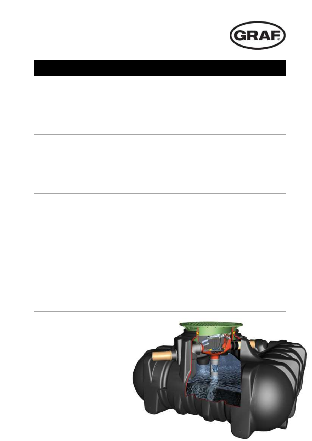
MINIMAX-PRO
DE
Anleitung für Einbau und Wartung
GRAF MINIMAX-PRO Filter Intern
>> Seite 1-9
EN
Instruction for installation and maintenance
GRAF MINIMAX-PRO Filter internal
>> Page 10-18
FR
Notice de montage et d’utilisation
GRAF Filtre MINIMAX-PRO Interne
>> Page 19-27
ES
Instrucciones para la instalación y mantenimiento del
filtro Interno MINIMAX-PRO
>> Página 28-36
Page 2

Otto Graf GmbH
Kunststofferzeugnisse
Carl-Zeiss-Str. 2-6
D-79331 Teningen
Tel.: +49 7641 589-66
Fax: +49 7641 589-50
mail@graf.info
www.graf-online.de
Page 3

info@graf.info
Anleitung für Einbau und Wartung
GRAF MINIMAX-PRO Filter Intern
MINIMAX-PRO Filter Intern
mit gebogenem / geradem
Abgang
Art.-Nr. 340093
Platin Ausbaupaket 3
Art.-Nr. 342038
Carat Ausbaupaket
Art.-Nr. 340119
Die in dieser Anleitung
beschriebenen Punkte sind
unbedingt zu beachten. Bei
Nichtbeachtung erlischt jeglicher
Garantieanspruch. Für alle über
GRAF bezogenen Zusatzartikel
erhalten Sie separate in der
Transportverpackung beiliegende
Einbauanleitungen.
Eine Überprüfung der
Komponenten auf eventuelle
Beschädigungen hat unbedingt vor
der Installation zu erfolgen.
Fehlende Anleitungen können Sie
unter www.graf.info downloaden
oder bei GRAF anfordern.
Inhaltsübersicht
1. ALLGEMEINE HINWEISE 2
1.1 Sicherheit 2
2. EINBAUBEDINGUNGEN 2
2.1 MINIMAX-PRO Filter Intern 2
3. TECHNISCHE DATEN 3
3.1 Abmessungen mit gebogenem Abgang 3
3.2 Abmessungen mit geradem Abgang 4
4. AUFBAU 5
5. EINBAU UND MONTAGE 5
5.1 Übersicht Platin Tank 5
5.2 Montage Zulaufrohr und Siphon 6
5.3 Filter zum Einsetzen vorbereiten 6
5.4 Filter in den Tank einsetzen 7
5.5 Übersicht Carat Tank 7
5.6 Montage Zulaufrohr und Siphon 8
5.7 Filter zum Einsetzen vorbereiten 8
5.8 Filter in den Tank einsetzen 9
6. ZUBEHÖR 9
7. WARTUNG 9
www.graf.info
1 / 36
Page 4

info@graf.info
1. Allgemeine Hinweise
2. Einbaubedingungen
www.graf.info
1.1 Sicherheit
Bei sämtlichen Arbeiten sind die einschlägigen Unfallverhütungsvorschriften nach BGV C22 zu beachten.
Besonders bei Begehung der Behälter ist eine 2. Person zur Absicherung erforderlich.
Des Weiteren sind bei Einbau, Montage, Wartung, Reparatur usw. die in Frage kommenden Vorschriften
und Normen zu berücksichtigen. Hinweise hierzu finden Sie in den dazugehörigen Abschnitten dieser
Anleitung.
Die Firma GRAF bietet ein umfangreiches Sortiment an Zubehörteilen, die alle aufeinander abgestimmt
sind und zu kompletten Systemen ausgebaut werden können. Die Verwendung anderer Zubehörteile
kann dazu führen, dass die Funktionsfähigkeit der Anlage beeinträchtigt und die Haftung für daraus
entstandene Schäden aufgehoben wird.
2.1 MINIMAX-PRO Filter Intern
Der MINIMAX-PRO Filter Intern ist geeignet für den Einbau in einen Vorschacht oder eine
Zisterne
Der Höhenunterschied zwischen Zulauf und Ablauf beträgt bei geradem Abgang 10 mm und bei
gebogenem Abgang 80 mm.
Der Filter ist geeignet für Dachflächen bis 350 m².
Die Maschenweite des Siebeinsatzes beträgt 0,35 mm.
2 / 36
Page 5

110
110
110
365
270
Zulauf
Ablauf
Tank
Siphon
790
80
Fließrichtung
270
620
110
110
365
270
Zulauf
Ablauf
Tank
270
620
110
110
365
270
Ablauf
Tank
365
270
365
270
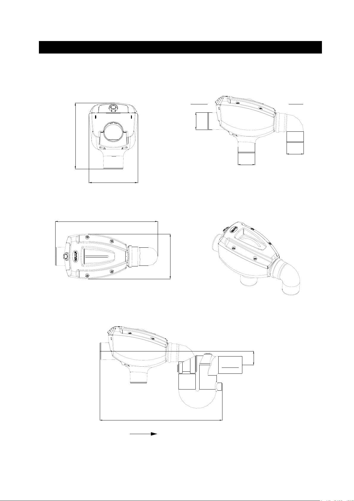
3. Technische Daten
tank
3.1 Abmessungen mit gebogenem Abgang
info@graf.info
www.graf.info
3 / 36
Page 6
270
500
110
365
270
Ablauf
Tank
110
110
110
365
270
Zulauf
Ablauf
Tank
110
500
Fließrichtung
270
500
110
365
270
Zulauf
Ablauf
Tank
110
10
365
270
365
270
3. Technische Daten
tank
3.2 Abmessungen mit geradem Abgang
info@graf.info
www.graf.info
4 / 36
Page 7
1
2
3
6
5
4
6
5
4
3
6
5
4
2
3
6
5
4
185
265
185
265
185
265
4. Aufbau
5. Einbau und Montage
Transparenter Deckel/
Siebeinsatz
Gehäuse inklusive Düsenhalter
Abgangsbogen 87°
info@graf.info
www.graf.info
optionale Reinigungseinheit
(340040)
5.1 Übersicht Platin Tank / Filter mit gebogenem Abgang
5 / 36
Page 8
info@graf.info
L
2
3
L
2
3
1 1
2
1
Platin Tank
1500 L
3000 L
5000 L
7500 L
[L]
470 mm*
500 mm*
675 mm*
1075 mm*
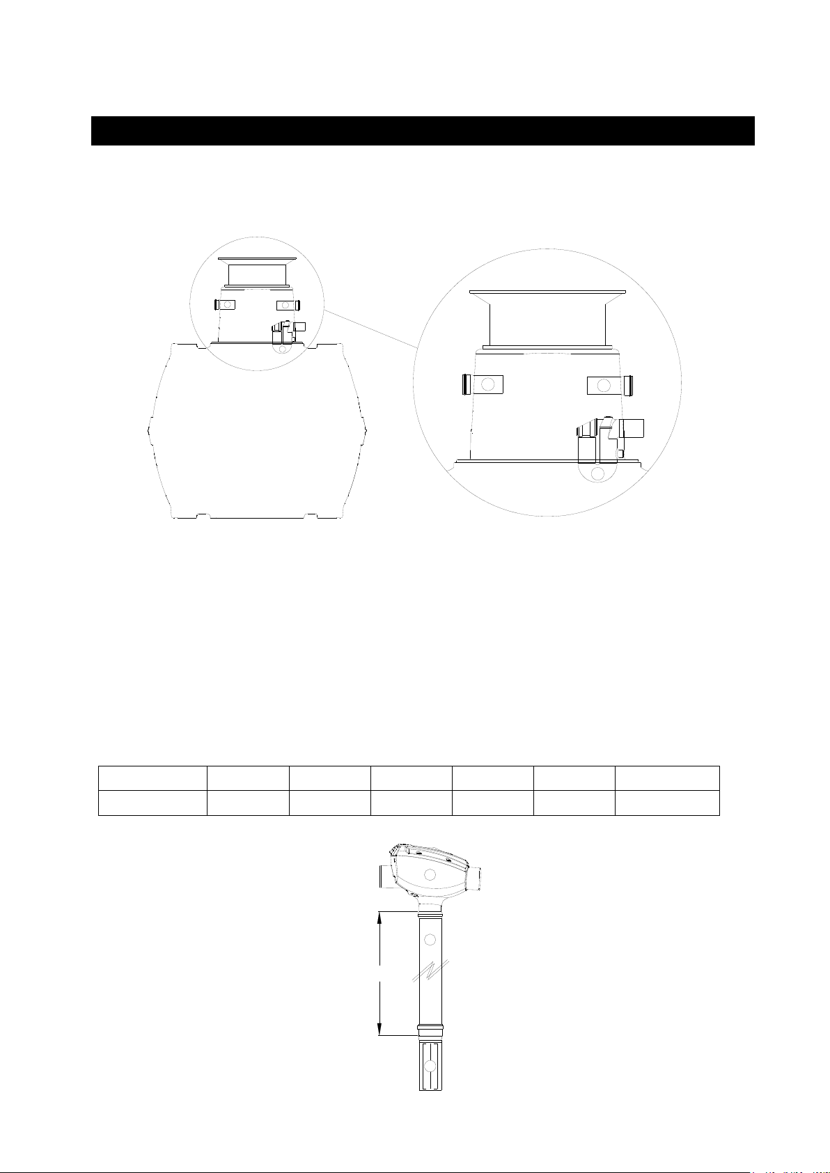
5. Einbau und Montage
* (+/- 10 mm)
www.graf.info
5.2 Montage Zulaufrohr und Siphon
Siphon in die unterste Dichtung am Tankdom bis zum Anschlag einschieben.
Zulaufrohr Länge 150 mm von außen gegenüberliegend einschieben.
5.3 Filter zum Einsetzen vorbereiten
Das Filtergehäuse mit einem bauseits zu stellenden KG/HT Rohr DN 100 mit dem beruhigten
Zulauftopf (im Ausbaupaket 342038 enthalten) verbinden.
Alle Verbindungsstellen mit handelsüblichen Spaxschrauben gegen Auseinanderrutschen sichern.
6 / 36
Page 9
info@graf.info
245 245
520
5. Einbau und Montage
5. Einbau und Montage
www.graf.info
5.4 Filter in den Tank einsetzen
Den mit dem beruhigten Zulauf und Zulauftopf vorbereiteten Filter in den Tank einsetzen.
Dabei den Abgangsbogen des Filters von oben in den Überlaufsiphon einschieben sowie das Zulaufrohr
bündig zum Filter ausrichten und anschließend mit der Schnellmontage-Manschette (im Ausbaupaket
342038 enthalten) fixieren.
5.5 Übersicht Carat Tank / Filter mit geradem Abgang
7 / 36
Page 10
1
2
2
1
2
2
L
2
3
Carat Tank
2700 L
3750 L
4800 L
6500 L
8500 L
10000 L
[L]
1190 mm*
1380 mm*
1610 mm*
1890 mm*
1790 mm*
1990 mm*
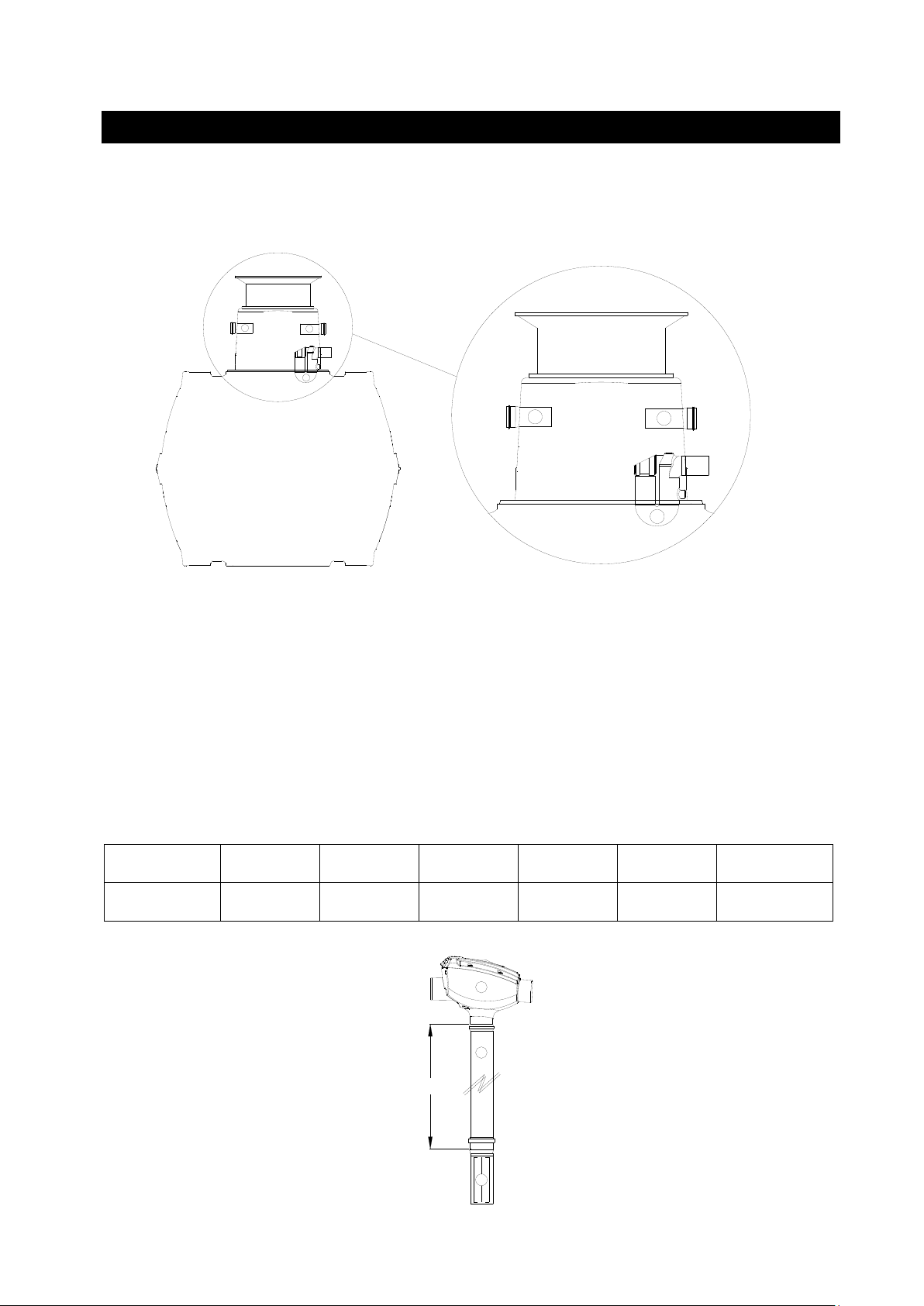
5. Einbau und Montage
5.6 Montage Zulaufrohr und Siphon
info@graf.info
www.graf.info
Siphon in die unterste Dichtung am Tankdom bis zum Anschlag einschieben.
Zulaufrohre Länge 150 mm von außen gegenüberliegend einschieben.
5.7 Filter zum Einsetzen vorbereiten
Das Filtergehäuse mit einem bauseits zu stellenden KG/HT Rohr DN 100 mit dem beruhigten
Zulaufrohr (im Ausbaupaket 340119 enthalten) verbinden.
Alle Verbindungsstellen mit handelsüblichen Spaxschrauben gegen Auseinanderrutschen sichern.
* (+/- 10 mm)
8 / 36
Page 11
500
6. Zubehör
7. Wartung
5. Einbau und Montage
Otto Graf GmbH – Carl-Zeiss-Str. 2-6 – DE-79331 Teningen – Tel.: +49 7641 589-0 – Fax: +49 7641 589-50
GRAF Distribution S.A.R.L – 45, route d´Ernolsheim – FR-67120 Dachstein Gare – Tél.:+33 388 49-7310 – Fax: +33 388 49-3280
GRAF Iberica Tecnología del Plástico S.L. – Marquès Caldes de Montbui, 114 – ES-17003 Girona – Tel.: +34 972 913767 – Fax: +34 972 913766
GRAF UK Ltd – Target House – Thorpe Way Ind. Estate – Banbury – Oxfordshire – UK-OX16 4SP – Tel.: +44 1608 661-500 – Fax: + 44 1608 665-466
2014-05
5.8 Filter in den Tank einsetzen
info@graf.info
www.graf.info
Den mit dem beruhigten Zulauf und Zulauftopf vorbereiteten Filter in den Tank einsetzen.
Dabei Zulauf- sowie Ablaufrohr bündig zum Filter ausrichten und anschließend mit den beiden
Schnellmontage-Manschetten (im Ausbaupaket 340119 enthalten) fixieren.
Auf keinen Fall dürfen im Ablauf Kleintiersperren installiert werden, da es durch Schmutz der zum
Kanal geleitet wird zu Rohrverstopfungen kommen kann.
Griff XL für MINIMAX-PRO Filter Intern
Art.-Nr. 330220
Je nach Schmutzanfall im Dachablaufwasser muss die Siebfläche des MINIMAX-PRO Filters Intern
mehrmals im Jahr gereinigt werden. Beim Abnehmen des transparenten Deckels bleibt der Siebeinsatz
an diesem hängen und kann somit Problemlos entnommen und gereinigt werden.
9 / 36
Page 12
info@graf.info
Instruction for installation and maintenance
GRAF MINIMAX-PRO Filter internal
MINIMAX-PRO Filter internal
with curved / straight outlet
Order No. 340093
Platin Package 3
Order No. 342038
Carat Package
Order No. 340119
The points described in these
instructions must be observed
under all circumstances. All
warranty rights are invalidated in
the event of non-observance.
Separate installation instructions
are enclosed in the transportation
packaging for all additional articles
purchased from GRAF.
The components must be checked
for any damage prior to installation
under all circumstances.
Missing instructions can be
downloaded on www.graf.info or
can be requested from GRAF.
Table of contents
1. General notes 11
1.1 Safety 11
2. Installation conditions 11
2.1 MINIMAX-PRO Filter internal 11
3. Technical data 12
3.1 Dimensions with curved outwith curved outlet
4. Technical data 13
4.1 Dimensions straight outlet 13
5. Assembly 14
5. Installation and assembly 14
5.1 Overview Platin tank / Filter with curved outlet 14
5.2 Installation of inflow pipe and overflow siphon 15
5.3 Preparation filter for installation 15
5.4 Insert the filter into the tank 16
5. Installation and assembly 16
5.5 Overview Carat tank / Filter with straight outlet 16
5.6 Installation of inflow pipe and overflow siphon 17
5.7 Preparation filter for installation 17
5.8 Insert the filter into the tank 18
6. Accessory 18
7. Maintenance 18
66Acc 6. Accessory essory
www.graf.info
10 / 36
Page 13

info@graf.info
1. General notes
2. Installation conditions
www.graf.info
1.1 Safety
A second person is required for health & safety, in particular when entering the tank..
The relevant regulations and standards must additionally be taken into consideration during installation,
assembly, servicing, repair, etc. Relevant notes can be found in the corresponding sections of these
instructions.
During all work on the system or parts of the system, the entire system must always be rendered
inoperable and secured to prevent unauthorised reactivation The entire system must always be taken out
of action & secured against being switched on again whilst work, repair or maintainance is carried out on
parts of the system or the system.
Except when working in the tank; the tank cover must always be kept closed due to acute danger of
accident.
GRAF offers an extensive range of genuine parts & accessories, all of which are designed to ensure the
system performs as specified. The use of non-genuine Grafparts or accessories may lead to the
system's functional capability or failure, therefore invalidating Warranties & Guarantees and liability for
resulting damage.
2.1 MINIMAX-PRO Filter internal
The MINIMAX-PRO Filter is suitable for installation in a manhole or a underground tank.
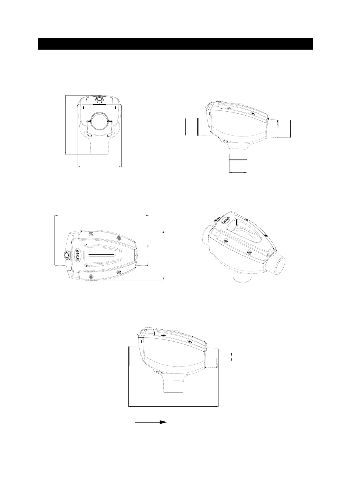
The difference in height between inlet and outlet is around 10 mm with a straight outlet and 80
mm with a curved outlet.
The filter is suitable for roof areas up to 350 m².
The mesh width of the sieve insert is 0.35 mm.
11 / 36
Page 14

110
110
110
365
270
Zulauf
Ablauf
Tank
Siphon
790
80
Fließrichtung
270
620
110
110
365
270
Zulauf
Ablauf
Tank
270
620
110
110
365
270
Ablauf
Tank
365
270
365
270
3. Technical data
inlet
outlet
flow direction
tank
info@graf.info
www.graf.info
3.1 Dimensions with curved outlet
12 / 36
Page 15

270
500
110
365
270
Ablauf
Tank
110
110
110
365
270
Zulauf
Ablauf
Tank
110
500
Fließrichtung
270
500
110
365
270
Zulauf
Ablauf
Tank
110
10
365
270
365
270
3. Technical data
inlet
outlet
Flow direction
tank
3.2 Dimensions with straight outlet
info@graf.info
www.graf.info
13 / 36
Page 16

info@graf.info
185
265
185
265
185
265
4. Assembly
5. Installation and assembly
www.graf.info
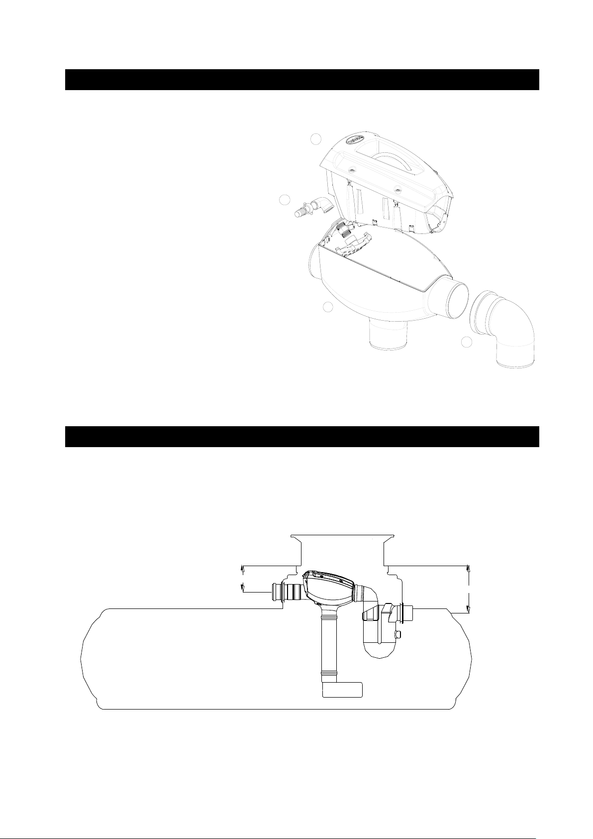
Clear transparent cover/
Filter insert
Housing including nozzle holder
Outlet bend 87°
Optional cleaning unit
(340040)
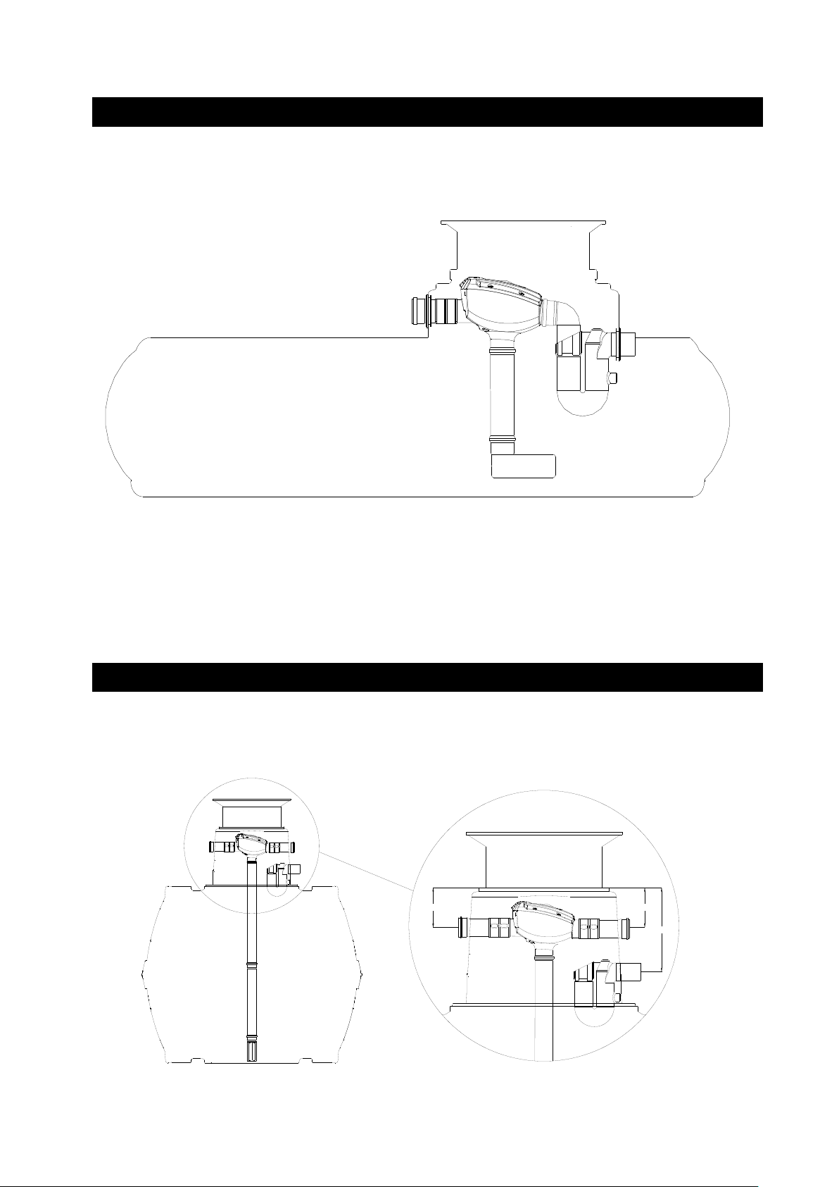
5.1 Overview Platin tank / Filter with curved outlet
14 / 36
Page 17

info@graf.info
2
1
L
2
3
L
2
3
1 1
Platin tank
1500 L
3000 L
5000 L
7500 L
[L]
470 mm*
500 mm*
675 mm*
1075 mm*
5. Installation and assembly
* (+/- 10 mm)
www.graf.info
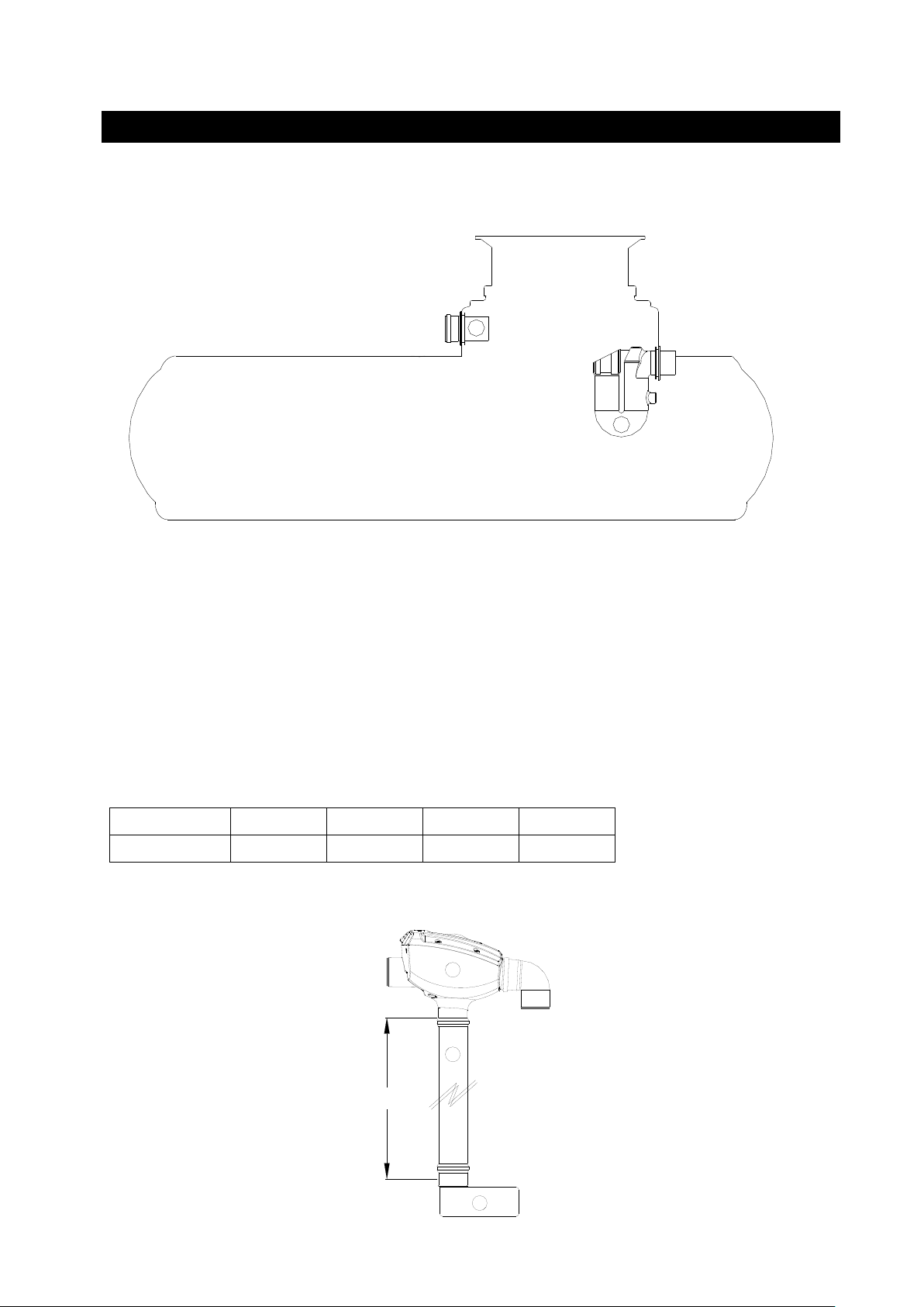
5.2 Installation of inflow pipe and overflow siphon
Insert the overflow siphon in the lower seal till block.
Insert the inflow pipe DN100 from outside.
5.3 Preparation filter for installation
Connect the filter body with a PVC pipe DN 100 (on site) with the inflow Calming Foot
(contained in filter package 342038).
Secure or connections with Self Tapping screws to prevent connections separating.
15 / 36
Page 18

info@graf.info
245 245
520
5. Installation and assembly
5. Installation and assembly
www.graf.info
5.4 Insert the filter into the tank
Insert the filter, prepared with the inflow Calming foot, in the tank.
Slide the outlet bend of the filter into the overflow siphon from above, align the supply pipe flush with the
filter and then fix with the quick-connection sleeve (included in filter package 342038).
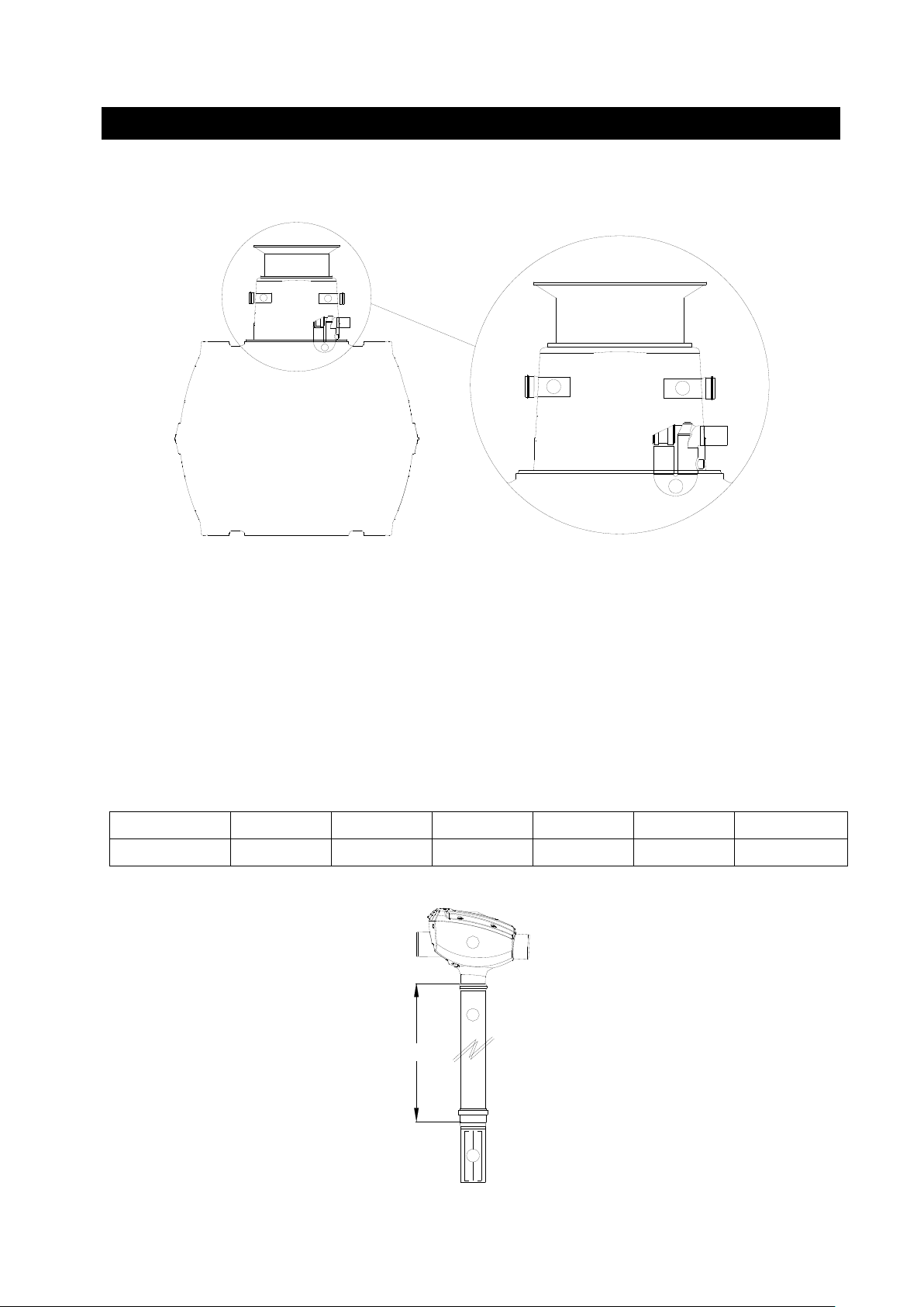
5.5 Overview of Carat tank / filter with straight outlet
16 / 36
Page 19

info@graf.info
1
2
2
1
2
2
L
2
3
Carat tank
2700 L
3750 L
4800 L
6500 L
8500L
10000 L
[L]
1190 mm*
1380 mm*
1610 mm*
1890 mm*
1790 mm*
1990 mm*
5. Installation and assembly
* (+/- 10 mm)
www.graf.info
5.6 Installation of inflow pipe and overflow siphon
Insert the overflow siphon in the lower seal till block.
Insert the inflow pipe DN100 from outside.
5.7 Preparation filter for installation
Connect the filter body with a PVC pipe DN 100 (on site) with the inflow Calming Foot
(contained in filter package 340119).
Fix all junctions with screws (against shift of pipes.
17 / 36
Page 20

info@graf.info
5. Installation and assembly
6. Accessory
7. Maintenance
Otto Graf GmbH – Carl-Zeiss-Str. 2-6 – DE-79331 Teningen – Tel.: +49 7641 589-0 – Fax: +49 7641 589-50
GRAF Distribution S.A.R.L – 45, route d´Ernolsheim – FR-67120 Dachstein Gare – Tél.:+33 388 49-7310 – Fax: +33 388 49-3280
GRAF Iberica Tecnología del Plástico S.L. – Marquès Caldes de Montbui, 114 – ES-17003 Girona – Tel.: +34 972 913767 – Fax: +34 972 913766
GRAF UK Ltd – Target House – Thorpe Way Ind. Estate – Banbury – Oxfordshire – UK-OX16 4SP – Tel.: +44 1608 661-500 – Fax: + 44 1608 665-466
2014-05
www.graf.info
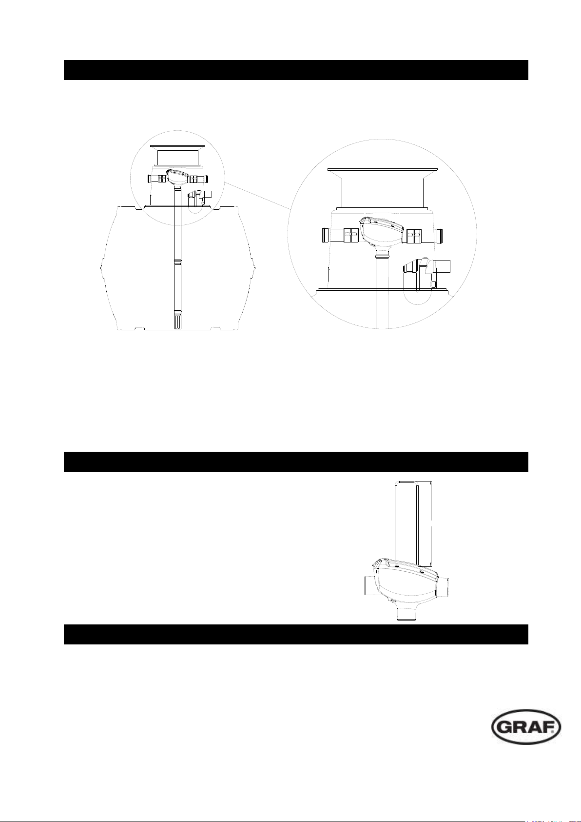
5.8 Insert the filter into the tank
Insert the filter, prepared with the inflow Calming Foot, in the tank.
Align the supply and drain pipes flush with the filter and then fix with the two quick-connection sleeves
(included in filter package 340119).
Rodent guards should never be installed in the Filter outlet as this could cause dirt to enter the drain and
block the pipe.
Handle XL for MINIMAX – PRO Filter
Order No. 330220
Depending on the dirtiness of the roof surface water the sieve has to be cleaned several times a year.
Remove the transparent cover from the filter body. The sieve and the cover is one unit. Removing and
cleaning is unproblematic.
18 / 36
Page 21

info@graf.info
Notice de montage et d’utilisation
GRAF Filtre MINIMAX-PRO Interne
Filtre MINIMAX-PRO Interne
Avec sortie coudée / droite
Réf. 340093
Platin Pack Accessoires n°3
Réf. 342038
Carat Pack Accessoires n°3
Réf. 340119
Afin de garantir le bon
fonctionnement et la longévité de
votre installation, il est important
de respecter scrupuleusement les
instructions de mise en place du
fabricant. Tout manquement à ces
règles annulera systématiquement
la garantie.
Avant d’installer les components, il
est important de vérifier que celleci n’a pas été endommagée.
Les notices manquantes peuvent
être téléchargées sur
www.graf.info ou être demandées
auprès de la société GRAF.
Sommaire
1. GÉNÉRALITÉS 20
1.1 Sécurité 20
2. CONDITIONS D’INSTALLATION 20
2.1 Filtre MINIMAX-PRO Interne 20
3. SPECIFICATIONS TECHNIQUES 21
3.1 Dimensions avec sortie coudée 21
3. SPECIFICATIONS TECHNIQUES 22
3.2 Dimensions avec sortie droite 22
4. ASSEMBLAGE 23
5. MISE EN PLACE ET MONTAGE 23
5.1 Aperçu du filtre pour cuve Platine 23
5.2 Connexion de l’arrivée et du siphon 24
5.3 Préparation de la pose du filtre 24
5.4 Pose du filtre dans la cuve 25
5.5 Aperçu réservoir Carat/filtre à sortie droite 25
5.6 Connexion de l’arrivée et du siphon 26
5.7 Préparation de la pose du filtre 26
5.8 Pose du filtre dans la cuve 27
6. Accessoire 27
7. Maintenance 27
www.graf.info
19 / 36
Page 22

info@graf.info
2. Conditions d’installation
1. Généralités
www.graf.info
1.1 Sécurité
Pour tous les travaux, les prescriptions de prévention des accidents applicables selon le BGV C22
doivent être respectées. Notamment pour marcher sur le réservoir, il faut une 2ème personne par
mesure de sécurité.
En outre, pour la mise en place, le montage, l’entretien, la réparation etc., il faut respecter les
prescriptions et les normes applicables en question. Vous trouverez des instructions à ce sujet dans les
paragraphes correspondants de cette notice d’utilisation.
Pour toutes les interventions effectuées sur le dispositif ou sur des parties du dispositif, il faut toujours
mettre l’ensemble du dispositif hors service et le protéger contre toute remise en marche inopinée.
La société GRAF propose une gamme très complète d’accessoires qui sont tous adaptés les uns aux
autres et qui peuvent être étendus en systèmes complets. L’utilisation d’autres accessoires risque
d’altérer le bon fonctionnement du dispositif et, de ce fait, annuler la garantie en cas de dommages.
2.1 Filtre MINIMAX Interne Pro
Le filtre MINIMAX-Pro est prévu pour être installé dans une cuve ou un regard de visite.
La différence de hauteur entre l’alimentation et l’évacuation fait 10 mm pour une sortie droite et
80 mm pour une sortie pliée.
Le filtre est adapté aux toitures jusqu’à 350 m2.
La maille du filtre est de 0,35 mm.
20 / 36
Page 23
110
110
110
365
270
Zulauf
Ablauf
Tank
Siphon
790
80
Fließrichtung
270
620
110
110
365
270
Zulauf
Ablauf
Tank
270
620
110
110
365
270
Ablauf
Tank
365
270
365
270
3. Spécifications techniques
entrée
sortie
sens de l’écoulement
cuve
3.1 Dimensions avec sortie coudée
info@graf.info
www.graf.info
21 / 36
Page 24

270
500
110
365
270
Ablauf
Tank
110
110
110
365
270
Zulauf
Ablauf
Tank
110
500
Fließrichtung
270
500
110
365
270
Zulauf
Ablauf
Tank
110
10
365
270
365
270
3. Spécifications techniques
entrée
sortie
sens de l’écoulement
tank
cuve
3.2 Dimensions avec sortie droite
info@graf.info
www.graf.info
22 / 36
Page 25

info@graf.info
185
265
185
265
185
265
4. Assemblage
5. Mise en place et Montage
www.graf.info
Couvercle transparent/
Plaque-filtre
Boîtier y compris fixation rampe de lavage
Coude sortie 87°
Rampe de lavage optionnelle
(340040)
5.1 Aperçu du filtre pour cuve platine / Filtre à sortie coudée
23 / 36
Page 26

info@graf.info
2
1
L
2
3
L
2
3
1 1
5. Mise en place et Montage
la cuve Platine
1500 L
3000 L
5000 L
7500 L
[L]
470 mm*
500 mm*
675 mm*
1075 mm*
* (+/- 10 mm)
www.graf.info
5.2 Connexion de l’arrivée et du siphon
Insérez le siphon dans le joint inférieur jusqu’ à la butée.
Tuyau d’arrivée Longueur 150 mm à introduire de l’extérieur.
5.3 Préparation de la pose du filtre
Raccorder le corps de filtre au tuyau anti-remous PCV DN 100 fourni et compris dans le pack
accessoire n°3. Le sabot et tuyau anti-remous est à raccorder et à utiliser uniquement pour les cuves
de capacités de 7800 L et 9200 L. Les connexions sont à sécuriser à l'aide de vis (types vis à bois) pour
éviter que l'ensemble glisse.
24 / 36
Page 27

info@graf.info
245 245
520
5. Mise en place et Montage
5. Mise en place et Montage
www.graf.info
5.4 Pose du filtre dans la cuve
Placez le filtre avec le sabot et tuyau anti-remous dans la cuve.
Pousser le coude de sortie du filtre par le haut dans le siphon de trop-plein et le tuyau d’alimentation,
ajuster le tuyau d’alimentation sur le filtre et fixer ensuite à l’aide de la manchette à montage rapide
(comprise dans l’ensemble de montage 342038).
5.5 Aperçu réservoir Carat/filtre à sortie droite
25 / 36
Page 28
info@graf.info
1
2
2
1
2
2
L
2
3
5. Mise en place et Montage
la cuve Carat
2700 L
3750 L
4800 L
6500 L
8500 L
10000 L
[L]
1190 mm*
1380 mm*
1610 mm*
1890 mm*
1790 mm*
1990 mm*
www.graf.info
5.6 Connexion de l’arrivée et du siphon
Insérez le siphon dans le joint inférieur jusqu’ à la butée.
Tuyau d’arrivée Longueur 150 mm à introduire de l’extérieur.
5.7 Préparation de la pose du filtre
Raccorder le corps de filtre au tuyau anti-remous PCV DN 100 fourni et compris dans le pack
accessoire n°3. Le sabot et tuyau anti-remous est à raccorder et à utiliser uniquement pour les cuves
de capacités de 7800 L et 9200 L. Les connexions sont à sécuriser à l'aide de vis (types vis à bois) pour
éviter que l'ensemble glisse.
* (+/- 10 mm)
26 / 36
Page 29

info@graf.info
6. Accessoire
7. Maintenance
5. Mise en place et Montage
Otto Graf GmbH – Carl-Zeiss-Str. 2-6 – DE-79331 Teningen – Tel.: +49 7641 589-0 – Fax: +49 7641 589-50
GRAF Distribution S.A.R.L – 45, route d´Ernolsheim – FR-67120 Dachstein Gare – Tél.:+33 388 49-7310 – Fax: +33 388 49-3280
GRAF Iberica Tecnología del Plástico S.L. – Marquès Caldes de Montbui, 114 – ES-17003 Girona – Tel.: +34 972 913767 – Fax: +34 972 913766
GRAF UK Ltd – Target House – Thorpe Way Ind. Estate – Banbury – Oxfordshire – UK-OX16 4SP – Tel.: +44 1608 661-500 – Fax: + 44 1608 665-466
2014-05
www.graf.info
5.8 Pose du filtre dans la cuve
Placez le filtre avec le sabot et tuyau anti-remous dans la cuve.
Ajuster à cet effet le tuyau d’alimentation ainsi que d’évacuation à fleur du filtre et fixer ensuite à l’aide
des deux manchettes à montage rapide (comprises dans l’ensemble de montage 340119).
Une grille anti nuisible peut-être installée en sortie du trop-plein.
Bras XL pour filtre MINIMAX-PRO
Réf. 330220
Nettoyer plusieurs fois par an le filtre MINIMAX-PRO pour enlever les saletés provenant des toitures. La
grille filtrante est fixée au couvercle transparent, ce qui permet une prise aisée pour le nettoyage.
27 / 36
Page 30

info@graf.info
Instrucciones para la instalación y mantenimiento del
filtro Interno MINIMAX-PRO
Filtro Interno MINIMAX-PRO
Con salida curvada/recta
Nº pedido 340093
Pack Platin
Nº pedido 342038
Pack Carat
Nº pedido 340119
Se deben tener en cuenta
obligatoriamente todos los puntos
indicados en estas instrucciones. En
caso de no seguir estas
indicaciones se perderán todos los
derechos de garantía. Para todos
los artículos complementarios
adquiridos a través de GRAF, se
suministran instrucciones de
instalación adjuntos a los embalajes
de transporte.
Se debe realizar una revisión de los
componentes por si hubiera daños
antes de la instalación.
En caso de no disponer de las
instrucciones de montaje las puede
descargar en www.graf.info o
solicitarlas a Graf.
Índice de contenido
1. Indicaciones generales 29
1.1 Seguridad 29
2. Condiciones de Instalacion 29
2.1 Filtro Interno MINIMAX PRO 29
3. Datos técnicos 30
3.1 Medidas con salida curvada 30
3. Datos técnicos 31
3.2 Medidas con salida recta 31
4. Instalacion 32
5. Instalación y ensamblaje 32
5.1 Instalacion en depósito Platin 32
5.2 Instalacion tubo de alimentación y sifón 33
5.3 Preparación del filtro para la colocación 33
5.4 Colocar el filtro en el DEPOSITO 34
5.5 Instalacion en deposito Carat 34
5.6 Instalacion tubo de alamentación y sifón 35
5.7 Preparación del filtro para la colocación 35
5.8 Colocar el filtro en el 36
6. Accesorios 36
7. Mantenimiento 36
www.graf.info
28 / 36
Page 31

info@graf.info
1. Indicaciones generales
2. Condiciones de instalación
www.graf.info
1.1 Seguridad
En la ejecución de todos los trabajos deben seguirse las prescripciones pertinentes de prevención de
accidentes según BGV C22. Particularmente, en la inspección personal del depósito se requiere una
segunda persona para fines de seguridad.
Por lo tanto se deben seguir las prescripciones y normas correspondientes a la ejecución de los trabajos
de instalación, montaje, mantenimiento y reparación. Encontrará mayor información en los párrafos
correspondientes en estas instrucciones.
Antes de la ejecución de los trabajos en el equipo o en piezas individuales del equipo debe ponerse toda
la instalación fuera de servicio, protegiéndola simultáneamente contra una puesta en marcha no
autorizada.
La compañía GRAF ofrece un amplio surtido de accesorios que han sido adaptados entre sí y que
pueden ampliarse para formar sistemas completos. La utilización de otros accesorios puede provocar la
pérdida de funcionalidad de la instalación, de modo que el fabricante no asume la responsabilidad de los
daños generados en estos casos.
2.1 Filtro Interno MINIMAX-PRO
El filtro MINIMAX-PRO es apto para su instalación en una arqueta externa o en un depósito.
El desnivel entre la entrada y la salida es de 10 mm con salida recta y de 80 mm con salida
curvada.
El filtro es apto para superficies de recogida de hasta 350 m².
El tamaño de la malla del filtro es de 0,35 mm.
29 / 36
Page 32

110
110
110
365
270
Zulauf
Ablauf
Tank
Siphon
790
80
Fließrichtung
270
620
110
110
365
270
Zulauf
Ablauf
Tank
270
620
110
110
365
270
Ablauf
Tank
365
270
365
270
3. Datos técnicos
entrada caudal
salida caudal
Dirección del caudal
deposito
3.1 Medidas con salida curvada
info@graf.info
www.graf.info
30 / 36
Page 33

270
500
110
365
270
Ablauf
Tank
110
110
110
365
270
Zulauf
Ablauf
Tank
110
500
Fließrichtung
270
500
110
365
270
Zulauf
Ablauf
Tank
110
10
365
270
365
270
3. Datos técnicos
entrada caudal
Salida caudal
Dirección del caudal
deposito
3.2 Medidas con salida recta
info@graf.info
www.graf.info
31 / 36
Page 34

185
265
185
265
185
265
5. Instalación y ensamblaje
4. Ensamblaje
Tapa transparente/
Filtro
Estructura
Codo de salida de 87°
info@graf.info
www.graf.info
Unidad de limpieza opcional
(340040)
5.1 Instalación en depósito Platin / Filtro Minimax Pro con salida curvada
32 / 36
Page 35

info@graf.info
2
1
L
2
3
L
2
3
1 1
Depósito Platin
1500 L
3000 L
5000 L
7500 L
[L]
470 mm*
500 mm*
675 mm*
1075 mm*
5. Instalación y ensamblaje
* (+/- 10 mm)
www.graf.info
5.2 Instalación tubo de alimentación y sifón
Instalar el sifón en la junta más inferior de la cúpula del tanque hasta que haga tope
Colocar el tubo de alimentación longitud 150 mm desde fuera.
5.3 Preparación del filtro para la colocación
Conectar la carcasa del filtro con un tubo de PVC DN 100 a colocar durante el montaje con la
zapata de entrada tranquila (contenida en el Pack filtración).
Asegurar contra el desplazamiento todas las conexiones con tornillos de fijación.
33 / 36
Page 36

info@graf.info
245 245
520
5. Instalación y ensamblaje
5. Instalación y ensamblaje
www.graf.info
5.4 Colocar el filtro en el tanque
Colocar el filtro preparado con la zapata de entrada tranquila en el depósito.
Simultáneamente introducir desde arriba el codo de salida del filtro en el sifón de desagüe,
alinear de forma precisa el tubo de alimentación con el filtro y a continuación fijarlo por medio del
manguito de montaje rápido Spannfix (incluido en el paquete adicional 342038).
5.5 Instalación en depósito Carat / filtro Minimax Pro con salida recta
34 / 36
Page 37
info@graf.info
1
2
2
1
2
2
L
2
3
Depósito
Carat
2700 L
3750 L
4800 L
6500 L
8500L
10000 L
[L]
1190 mm*
1380 mm*
1610 mm*
1890 mm*
1790 mm*
1990 mm*
5. Instalación y ensamblaje
* (+/- 10 mm)
www.graf.info
5.6 Instalación tubo de alimentación y sifón
Instalar el sifón en la junta más inferior de la cúpula del depósito hasta que haga tope
Colocar el tubo de alimentación longitud 150 mm desde fuera.
5.7 Preparación del filtro para la colocación
Conectar la carcasa del filtro con un tubo de PVC DN 100 a colocar durante la instalación con la
zapata de entrada tranquila (contenida en el Pack filtración).
Asegurar contra el desplazamiento todas las conexiones con tornillos de fijación.
35 / 36
Page 38

6. Accesorios
7. Mantenimiento
5. Instalación y ensamblaje
Otto Graf GmbH – Carl-Zeiss-Str. 2-6 – DE-79331 Teningen – Tel.: +49 7641 589-0 – Fax: +49 7641 589-50
GRAF Distribution S.A.R.L – 45, route d´Ernolsheim – FR-67120 Dachstein Gare – Tél.:+33 388 49-7310 – Fax: +33 388 49-3280
GRAF Iberica Tecnología del Plástico S.L. – Marquès Caldes de Montbui, 114 – ES-17003 Girona – Tel.: +34 972 913767 – Fax: +34 972 913766
GRAF UK Ltd – Target House – Thorpe Way Ind. Estate – Banbury – Oxfordshire – UK-OX16 4SP – Tel.: +44 1608 661-500 – Fax: + 44 1608 665-466
2014-05
5.8 Colocar el filtro en el tanque
info@graf.info
www.graf.info
Colocar el filtro preparado con la zapata de entrada tranquila en el depósito.
Simultáneamente alinear de forma precisa el tubo de alimentación y el tubo de desagüe con el filtro y a
continuación fijarlos por medio de los dos manguitos de montaje rápido Spannfix (incluidos en el paquete
adicional 340119).
En ningún caso se deben instalar barreras para animales pequeños en la salida, ya que debido a la
suciedad que es conducida al canal se pueden producir obstrucciones de los tubos.
Asa XL para filtros MINIMAX-PRO
Nº pedido 330220
Limpiar el área filtrante del filtro MINIMAX-PRO varias veces al año acorde a la suciedad que transporte
el desagüe. Al extraer la tapa transparente el filtro permanece colgado de la misma y de esta manera se
puede sacar sin problemas y limpiarlo.
36 / 36
Page 39

Notizen / Notes / Notas
Page 40

 Loading...