

Page 1

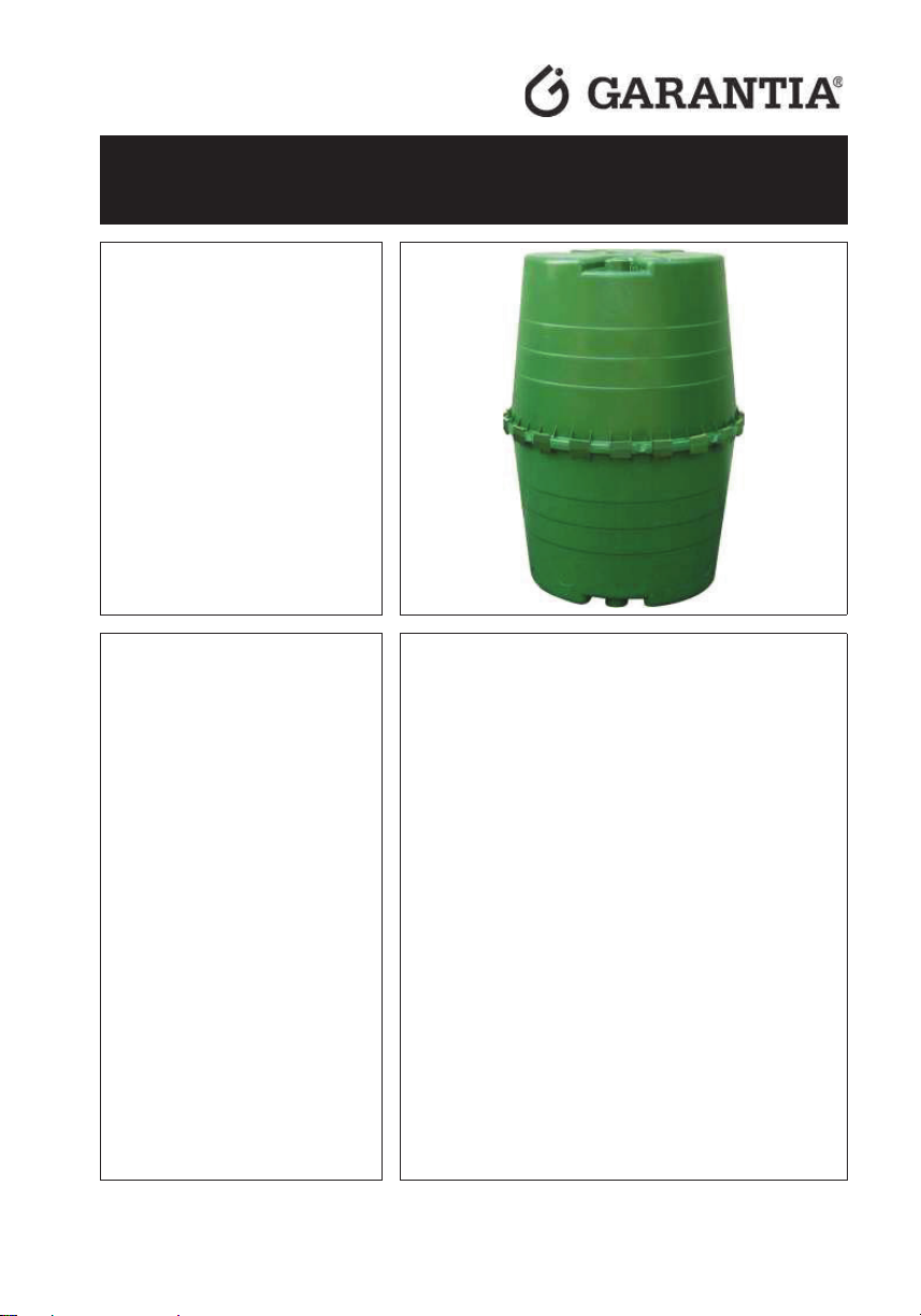
GRAF Top
-Tank
Art.
Die in dieser Anleitung
beschriebenen Punkte sind
un
Nichtbeachtung erlischt jeglicher
Garantieanspruch. Für alle über
GRAF bezogenen Zusatzartikel
erhalten Sie se
Transport
ckung beiliegende
Einbau
Fehlende Anleitu
umgehend bei uns anzufordern.
Eine Überprüfung der Behälter auf
eventuelle Beschädigungen hat
unbedingt vor dem Versetzen in
die Baugrube zu erfolgen.
Fehlende Anleitungen können Sie
unter www.graf.info downloaden
oder bei GRAF anfordern.
Inhaltsübersicht
1.
3
1.1
3
1.2
3
2.
3
2.1
3
3.
3
3.1
3
3.2
3
4.
4
5.
4
5.1
4
5.2
4
6.
5
6.1
5
6.2
5
7.
5
-Nr.: 323001
Anleitung für Einbau und Wartung
GRAF Regenwasser- Speicher Top-Tank
bedingt zu beachten. Bei
parate in der
verpa
anleitungen.
ngen sind
ALLGEMEINE HINWEISE
Sicherheit
Kennzeichnungspflicht
AUFSTELLBEDINGUNGEN
Oberirdische Aufstellung
TRANSPORT UND LAGERUNG
Transport
Lagerung
TECHNISCHE DATEN
MONTAGE BEHÄLTER
Probemontage
Montage Behälter
OBERIRDISCHE AUFSTELLUNG
Verbindung mehrerer Behälter
Anschlüsse legen
INSPEKTION UND WARTUNG
1 / 21
Page 2

Eine Handelsmarke der Otto Graf GmbH
Carl-Zeiss-Str. 2-6
D-79331 Teningen
Tel.: +49 7641 589-66
Fax: +49 7641 589-50
info@garantia.de
www.garantia.de
Page 3

1. Allgemeine Hinweise
1.1 Sicherheit
2. Aufstellbedingungen
3. Transport und Lagerung
Bei sämtlichen Arbeiten sind die einschlägigen Unfallverhütungsvorschriften nach BGV C22 zu beachten.
Besonders bei Begehung von Behältern ist eine 2. Person zur Absicherung erforderlich.
Des Weiteren sind bei Einbau, Montage, Wartung, Reparatur usw. die in Frage kommenden Vorschriften
und Normen zu berücksichtigen. Hinweise hierzu finden Sie in den dazugehörigen Abschnitten dieser
Anleitung.
Bei sämtlichen Arbeiten an der Anlage bzw. Anlagenteilen ist immer die Gesamtanlage außer Betrieb zu
setzen und gegen unbefugtes Wiedereinschalten zu sichern.
Die Firma GRAF bietet ein umfangreiches Sortiment an Zubehörteilen, die alle aufeinander abgestimmt
sind und zu kompletten Systemen ausgebaut werden können. Die Verwendung anderer Zubehörteile
kann dazu führen, dass die Funktionsfähigkeit der Anlage beeinträchtigt und die Haftung für daraus
entstandene Schäden aufgehoben wird.
1.2 Kennzeichnungspflicht
Alle Leitungen und Entnahmestellen von Brauchwasser sind mit den Worten „Kein Trinkwasser“
schriftlich oder bildlich zu kennzeichnen (DIN 1988 Teil 2, Abs. 3.3.2.) um auch nach Jahren eine
irrtümliche Verbindung mit dem Trinkwassernetz zu vermeiden. Auch bei korrekter Kennzeichnung kann
es noch zu Verwechslungen kommen, z.B. durch Kinder. Deshalb müssen alle Brauchwasser–
Zapfstellen mit Ventilen mit Kindersicherung installiert werden.
2.1 Oberirdische Aufstellung
x Die Behälter müssen auf ebenem, festen Untergrund ohne spitze Steine und ohne Gefälle
aufgestellt werden
x Bei Aufstellung das Gewicht des gefüllten Behälters beachten (1.350 kg).
x Bei Frostgefahr müssen die Behälter vollständig entleert werden.
x Bei Aufstellung in geschlossenen Räumen muss ein Bodenablauf vorhanden sein.
x Kinder sind in der Umgebung der Behälter zu beaufsichtigen.
3.1 Transport
Der Transport der Behälter darf nur mit geeignetem Transportmittel erfolgen. Während des Transportes
sind die Behälter gegen Verrutschen und Herunterfallen zu sichern. Werden die Behälter zum Transport
mit Spanngurten gesichert, ist zu gewährleisten, dass der Behälter unbeschädigt bleibt. Ein Verzurren
oder Anheben der Behälter mit Stahlseilen oder Ketten ist nicht zulässig.
Beanspruchungen durch Stöße sind unbedingt zu vermeiden. Auf keinen Fall dürfen die Behälter über
den Untergrund gerollt oder geschleift werden.
3.2 Lagerung
Eine notwendige Zwischenlagerung der Behälter muss auf geeignetem, ebenem Untergrund ohne spitze
Gegenstände erfolgen. Während der Lagerung muss eine Beschädigung durch Umwelteinflüsse oder
Fremdeinwirkung vermieden werden. Unbefugte Personen sind vom Behälter fernzuhalten.
3 / 21
Page 4
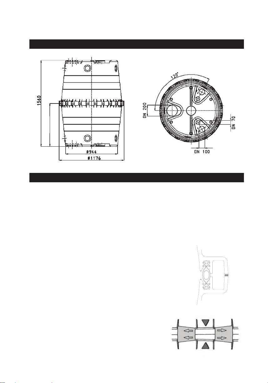
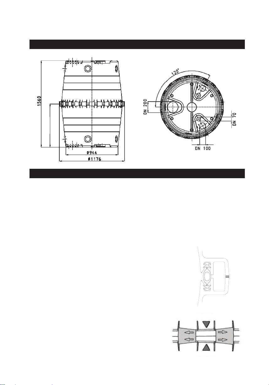
4. Technische Daten
5. Montage Behälter
5.1 Probemontage
Der Behälter besteht aus zwei baugleichen Halbschalen. Zur
Montage wird die eine Schale mit der geschlossenen Seite auf
einen ebenen Untergrund gestellt. Anschließend wird die
Profildichtung gut eingefettet und mit der geriffelten Seite in die
umlaufende, innere Nut g
B
aufgesetzt wird, muss die Dichtung und
die Nut der oberen Halbschale ebenfalls mit der Schmierseife
großzügig eingerieben werden. Beim Aufsetzen ist darauf zu
achten, dass die Dichtung nicht aus der Nut rutscht.
Zur Verbindung der Schalen werden die Schnellverbinder erst
linksherum und anschließend rechtsherum angebracht. Um die
Montage zu erleichtern kann es notwendig sein, beide
Halbschalen mit mehreren Schraubzwingen zusammenzudrücken.
zwingen am Behälterrand
verteilen und
Anschließend die Schnellverbinder von Hand ansetzen und mit
einem Hammer und einer Holzunterlage befe
tigen, die
Verbinder rasten in der En
Markierung oben
Markierung unten
Obere Halbschale
Untere Halbschale
Innenseite Tank
780
Der Behälter sollte vor der endgültigen Montage probeweise aufgestellt werden um folgende Anschlüsse
zu bestimmen:
x Zulauf
x Überlauf
Nach dem Öffnen der Anschlüsse müssen alle Bohr- bzw. Sägespäne aus dem Behälter entfernt werden.
5.2 Montage Behälter
edrückt.
evor die 2. Halbschale
Dazu ca. 3-4 Schraub
umlaufend gleichmäßig anziehen.
dposition ein.
s
4 / 21
Page 5

6. Oberirdische Aufstellung
Bei der oberirdischen Aufstellung ist darauf zu achten, dass der Behälter bei Frostgefahr vollständig
7. Inspektion und Wartung
2014-04
entleert wird. Weiterhin ist der Behälter auf einem ebenen, festen Untergrund ohne spitze Gegenstände
aufzustellen. Bei Aufstellung ist das Gesamtgewicht des gefüllten Behälters (1.350 kg) zu beachten. Der
Behälter sollte in schattiger Umgebung aufgestellt werden. Wird der Behälter in geschlossenen Räumen
installiert, so ist darauf zu achten, dass ein Bodenablauf vorhanden ist. Der Behälter darf nicht unter
Druck gesetzt werden, d.h. es muss in jedem Fall ein Überlauf im gleichen Durchmesser wie der Zulauf
installiert werden.
6.1 Verbindung mehrerer Behälter
Die Verbindung von zwei oder mehreren Behältern erfolgt über die unten am Behälter befin dlichen
Montageflächen mittels GRAF Spezialdichtungen und KG- Rohren. Die Öffnungen sind ausschließlich mit
dem GRAF Spezialkronenbohrer in der entsprechenden Größe zu bohren. Es ist darauf zu achten, dass
der Abstand zwischen den Behältern mind. 100 mm beträgt. Rohre müssen mind. 200 mm in die Behälter
hineinragen. Werden zwei oder mehr Behälter miteinander verbunden, muss neben der unteren
Verbindung auch eine obere Verbindung, zur Be- und Entlüftung, hergestellt werden.
6.2 Anschlüsse legen
Der Anschluss der Zu-/Überlaufleitungen erfolgt an vorgebohrten Öffnungen am Behälter oder an den
angeformten, zu öffnenden Stutzen.
Sämtliche Saug- bzw. Druck- und Steuerleitungen sind oberhalb des max. Wasserstandes
anzuschließen.
Die gesamte Anlage ist mind. alle drei Monate auf Dichtheit, Sauberkeit und Standsicherheit zu
überprüfen.
Eine Wartung der gesamten Anlage sollte in Abständen von ca. 5 Jahren erfolgen. Dabei sind alle
Anlagenteile zu reinigen und auf ihre Funktion zu überprüfen. Bei Wartungen sollte wie folgt vorgegangen
werden:
x Behälter restlos entleeren
x Feste Rückstände mit einem Hochdruckreiniger durch den 200er Stutzen entfernen
x Schmutz aus dem Behälter restlos entfernen
x Alle Einbauteile auf ihren festen Sitz überprüfen
5 / 21
Page 6
Installation instructions and maintenance
GRAF Top
Order No.: 32300
The points described in these
instructions must be observed
under all circumstances. All
warranty rights are invalidated in
the event of non
Separate installation instructions
are enclosed in the transportation
packaging for all additional articles
purchased from GRAF.
Missing instructions must be
requested from us immediately.
The tank must be checked for any
damage prior to insertion into the
trench under all circumstances.
Missin
downloaded on www.graf.info or
can be requested
Table of Contents
1.
7
1.1
7
1.2
7
2.
7
2.1
7
3.
7
3.1
7
3.2
7
4.
8
5.
8
5.1
8
5.2
8
6.
9
6.1
9
6.2
9
7.
9
-Tank
-observance.
g instructions can be
from GRAF.
GRAF rainwater reservoir Top-Tank
1
GENERAL NOTES
Safety
Identification obligation
INSTALLATION SET UP REQUIREMENTS
Assembly above ground
TRANSPORT AND STORAGE
Transport
Storage
TECHNICAL DATA
ASSEMBLY
Test installation
Installation tank
ASSEMBLY ABOVE GROUND
Joining multiple vessels
Laying connections
SERVICE AND MAINTENANCE
6 / 21
Page 7

info@garantia.eu
1. General notes
2. Installation set up requirements
3. Transport and storage
www.garantia.eu
1.1 Safety
The relevant accident prevention regulations according to BGV C22 have to be observed when
conducting any works. Especially when inspecting tanks a second person is required for safety reasons.
Furthermore, the relevant regulations and standards have to be observed during installation, assembly,
maintenance, repair, etc. You will find information about this in the related sections of these instructions.
During all works on the system respectively on system components the overall system has to be
decommissioned and secured against unintentional restart at all times.
The company GRAF offers a comprehensive portfolio of accessories that are aligned with each other and
can be developed into complete systems. Using deviating accessories can lead to impairments of the
functionality of the system and thus to the liability for damages resulting thereof expiring.
1.2 Identification obligation
All lines and tapping points of process water have to be labelled with the words “No drinking water” in
writing or visually (DIN 1988 part 2, section 3.3.2.) in order to avoid an accidental connection to the
drinking water network even after years. Even when there are correct labels, irritations are possible, e.g.
through children. That is why all tapping points of process water have to be installed with child-proof
valves.
2.1 Assembly above ground
x The tanks must be installed on an appropriate level and compacted surface that is free from
sharp objects and stones.
x Notice must be taken that the tanks when filled will weigh 1,350 kg
x When there is a danger of frost the tanks must be completely emptied.
x When the tanks are to be installed in a closed room, it is necessary to ensure that there is a floor
drainage system.
x Children must be supervised in the vicinity of the containers.
3.1 Transport
The transport of the tanks may only be undertaken with the appropriate transport machinery. During the
transport the tanks are to be secured against slipping or falling. If the tanks are secured for transportation
with webbing straps, it is to be ensured that the tanks remain undamaged. Dragging or lifting the tanks
with steel cables or chains is not permitted.
Stress and excess loading caused by impact are to be avoided. Under no circumstances are the tanks to
be rolled or slid over the ground surface.
3.2 Storage
Any necessary temporary storage of the tanks must be on an appropriate level surface without sharp
objects. During the storage it is important to avoid damage caused by the surrounding environment or
foreign objects. Unauthorized persons must be kept away from the tanks.
7 / 21
Page 8
info@garantia.eu
4. Technical data
5. Assembly
The tanks consist of two identically constructed halves. For the
assembly, the half with the closed side is positioned on the
compacted and level ground surface. The profiled sealing ring is
then well coated with lubricating soft soap and pressed with the
ribbed side into the continuous perimeter of the inner seat recess.
Before the second half of the tank is set in position, the seal and
the seat recess of the upper half must also be well coated with
the lubricating soft soap. During the assembly it is important to
ensure that the seal does not slip out of
To secure the two halves, the connection clips are fitted first in a
counter
clockwise direction and then in a clockwise direction. To
assist in the assembly it may be necessary to press the two tank
halves together with a number of G
lamps. To do this, position 3
to 4 G
clamps at equal intervals around the lip of the tank and
then begin to tighten them evenly. Finally position the connection
clips by hand and then drive them securely into place using a
hammer with a piece of wood in between, the clips will then
locate in the final engaged position
Upper marking
Lower marking
Upper tank half shell
Lower tank half shell
Internal tank side
780
www.garantia.eu
5.1 Test installation
The container should be assembled on a trial basis before the final assembly to determine the position
the following connections:
x Inlet
x Overflow
After opening the connections it is important to remove and clean all the drilling and sawing swarf from
the tank.
5.2 Installation tank
the seat recess.
-
-c
-
.
8 / 21
Page 9

info@garantia.eu
6. Assembly above ground
7. Service and maintenance
2014-04
www.garantia.eu
When installing the tanks above ground it is important to ensure that they are completely emptied when
there is any danger of frost. Furthermore, the tanks must be installed on an appropriate level and
compacted surface that is free from sharp objects and stones. Notice must be taken when installing the
tanks that the total weight when filled will be 1,350 kg. The tanks should also be installed in a shaded
area. When the tanks are to be installed in a closed room, it is necessary to ensure that there is a floor
drainage system on hand. The tanks are not designed to work under pressure and therefore it is
important to ensure that the overflow outlet has the same diameter as the inlet.
6.1 Joining multiple vessels
The coupling of two or more tanks is achieved by means of assembly areas moulded into the bases of the
tanks using GRAF special seals and canalisation pipes. The openings are only to be undertaken with the
special GRAF core drills (hole saw) in the appropriate sizes. It is important to note that the distance
between the tanks is a minimum of 100 mm. The pipes must extend into the tank at least 200 mm. If two
or more tanks are to be connected to one another then in addition to the lower connection (inlet) there
must also be an upper connection to ensure ventilation.
6.2 Laying connections
The connection of the inlet and overflow is by means of the pre-drilled openings of the tank or by means
of the pre-molded connection points intended for opening.
All the suction and pressure control lines must be installed and connected above the maximum water
level.
The system as a whole has to be checked for leaks, cleanliness, and stability at least every three months.
The system as a whole should be maintained every 5 years. In doing so, all system components have to
be cleaned and checked for functionality. Maintenance works should be conducted as follows:
x Empty tank completely
x Remove immovable residua using a pressure washer through the tank head
x Remove all contaminations from the tank
x Check all installation parts for proper seat
9 / 21
Page 10

GRAF RéservoirTop
Réf.: 32300
1
A
fonctionnement et la longévité de
votre installation, les diff
points décrits dans cette notice
doivent scrup
respectés. Tout manquement à ces
règles annulera systématiqu
ment
la garantie. Lisez ég
lement toutes
les notices des autres éléments
fournis par la société GRAF. Vous
trouv
rez les notices de montage
jointes dans l’emballage.
Toute notice manquante doit nous
être réclamée sans d
Avant de positionner la cuve dans la
fosse, il est important de vérifier que
celle
ci n’a pas été endommagée.
Les notices manquantes peuvent
être téléchargées sur www.graf.info
ou être demandées auprès de la
société GRAF.
Sommaire
1.
11
1.1
11
1.2
11
2.
11
2.1
11
3.
11
3.1
11
3.2
11
4.
12
5.
12
5.1
12
5.2
12
6.
13
6.1
13
6.2
13
7.
13
fin de garantir le bon
Notice d’installation et d’entretien
GRAF Réservoir Top-Tank 1300L
-Tank
uleusement être
a
e
-
élai.
érents
e
GÉNÉRALITÉS
Sécurité
Obligation de marquage
CONDITIONS D’INSTALLATION
Installation en aérien
TRANSPORT ET STOCKAGE
Transport
Stockage
DONNÉES TECHNIQUES
MONTAGE
Réalisation des perçages pour le raccordement
Montage du réservoir
INSTALLATION EN AÉRIEN
Jumelage de plusieurs réservoirs
Raccordement
INSPECTION ET ENTRETIEN
10 / 21
Page 11

info@garantia.eu
1. Généralités
2. Conditions d’installation
3. Transport et stockage
www.garantia.eu
1.1 Sécurité
l’inspection de la cuve, une 2ème personne doit être présente. Les instructions d’installation, de montage,
d’entretien et de réparation indiquées ci-après doivent être scrupuleusement respectées.
Durant toute intervention sur la cuve ou les accessoires, l’installation complète doit être mise hors
service.
La société GRAF vous propose une large gamme d’accessoires d’une grande compatibilité. L’utilisation
d’autres accessoires peut contribuer à un mauvais fonctionnement de l’installation. Les dommages subis
dans ce cas ne sont pas garantis.
1.2 Obligation de marquage
Afin d’éviter toute confusion, toutes les canalisations et sorties d’eau de pluie doivent être signalées par
la mention écrite ou en image « Eau non potable » pour éviter, même par erreur, tout raccord au réseau
d’eau potable. Toutes les sorties doivent être équipées de vannes « sécurité enfant ».
2.1 Installation en aérien
x Les réservoirs doivent être posés sur un sol compact et parfaitement plat, dépourvu d’éléments
pointus.
x Lors de la pose, considérer un poids total de 1.350 kg (poids du réservoir rempli).
x En cas de gel, les réservoirs doivent être vidés complètement.
x Dans le cas d’une installation dans une pièce fermée, un écoulement au sol doit être prévu.
x Surveiller les enfants lorsqu’ils s’approchent du réservoir .
3.1 Transport
L’enlèvement des cuves doit être effectué par une entreprise équipée de matériel adapté et du personnel
formé. Durant le transport, les cuves doivent être sécurisées, afin de ne pas glisser ou tomber du camion.
Si les cuves sont arrimées avec des sangles, il faut s’assurer que celles-ci n’endommagent pas les
cuves. L’utilisation de câbles en acier ou de chaînes pour amarrer ou soulever les cuves est proscrite.
3.2 Stockage
Le stockage des cuves doit se faire sur un sol adapté, plat et sans objet pointu. Durant le stockage,
veillez à ce qu’aucun élément extérieur ou environnemental n’endommage les cuves.
11 / 21
Page 12

info@garantia.eu
4. Données techniques
5. Montage
Le réservoir se compose de deux coques parfaitement
identiques. Poser l’une des coques sur un sol plat et stable,
ouverture vers le haut. Insérer le joint profilé dans la rainure de la
coque. Avant de placer la coque supérieure, bien graisser le joint
ainsi que la rainure de la coque supérieure à l’aide de la graisse
fournie.
Posez la première coque sur la seconde de façon à ce que la
jonction d'enclenchement se fasse dans la seule position
possible (alignez les parties pleines en face des creux :en face
des deux flèches). Pour cette opération, nous vous conseillons
d'être au minimum 2 personnes car il ne faut surtout pas écraser
le joint sinon celui
ci ne jouerait plus correctement son rôle
d'étanchéité. Lors de l’emboîtement des deux coques, veiller à ce
que le joint ne sorte pas de la rainure
Demi-coque
supérieure
Demi-coque
inférieure
Côté intérieur
780
www.garantia.eu
5.1 Réalisation des perçages pour le raccordement
Il est conseillé de simuler le montage du réservoir avant son installation afin de réaliser les perçages pour
le raccordement:
x Du fourreau
x De l’arrivée d’eau
Une fois les perçages effectués, retirer les résidus (copeaux) du réservoir et ébavurer les ouvertures.
5.2 Montage du réservoir
-
.
12 / 21
Page 13

info@garantia.eu
5. Montage
Pour le montage des 2 coques, il faut placer les clips de serrage.
Pour faciliter l’assemblage, il est recommandé de positionner 4
serre
joints sur le pourtour du réservoir, afin d’assurer un
maintien provisoir des 2 coques, en attendant la mise en place
définitive des clips de serrage.
Positionner les clips manuellement sur le pourtour du réservoir,
puis utiliser une câle en bois et un marteau pour serrer
définitivement les clips. Il ne faut pas taper directement avec le
marteau sur les clips.
6. Installation en aérien
7. Inspection et entretien
Marquage supérieure
Marquage inférieure
2014-04
www.garantia.eu
-
Dans le cas d’une posé en aérien, veiller à ce que le réservoir soit complètement vidé en cas de gel.
Placer le réservoir sur un sol stable et plan. Prendre en considération un poids total de 1.350 kg (poids du
réservoir rempli). Le réservoir doit être installé à l’ombre. Dans le cas d'une installation dans une pièce
fermée, prévoir une évacuation au sol. Le réservoir ne doit pas être mis sous pression, pour cela, le tuyau
de trop-plein doit être du même diamètre que le tuyau d’arrivée.
6.1 Jumelage de plusieurs réservoirs
Les réservoirs sont jumelables par le bas au niveau des surfaces planes, par le biais d’un set de joints
GRAFet d’un tuyau PVC. Les perçages sont à réaliser à l’aide de la scie -cloche GRAF. Veiller à ce que
les réservoirs soient espacés de 100 mm les uns des autres. Les tuyaux PVC doivent être insérés au
minimum de 200 mm dans les cuves. Dans le cas où deux ou plus de deux réservoirs doivent être
jumelés, un jumelage haut doit être réalise en plus du jumelage bas, pour jouer le rôle d’évent et de
ventilation.
6.2 Raccordement
Les raccordements d’entrée et de sortie peuvent se faire sur les marquages sur le c ôté de la cuve ou par
les manchons de raccordement situés sur le dessus de la cuve.
Les tuyaux de tirage et d’aspiration doivent être raccordé au dessus du trop plein de la cuve.
L’étanchéité, la propreté et la stabilité de l’ensemble de l’installation doit être contrôlé au minimum tous
les trois mois.
Un entretien de l’installation doit être effectué 5 ans après sa mise en place. Pour cela, nettoyer toutes
les pièces de l’installation et tester leur bon fonctionnement. Effectuer les étapes suivantes:
x Vider complètement le réservoir
x Utiliser un nettoyeur haute pression pour décoller les mousses et saletés des parois du réservoir
x Evacuer toutes les saletés de la cuve
x Contrôler le bon fonctionnement de toutes les pièces de l’installation
13 / 21
Page 14

Instrucciones para la instalación y mantenimiento
GRAF Top
Código: 32300
Se deben tener en cuenta
obligatoriamente todos los puntos
indicados en estas instrucciones. En
caso de no seguir estas
indicaciones se perderán todos los
derechos de garantía. Para todos
los artículos complementarios
adquiridos a través de GRAF, se
suministran instrucciones de
montaje adjuntos a los embalajes de
transporte.
Solicítenos inmediatamente las
instrucciones que puedan faltarle.
Se debe realizar una revisión de los
tanques por si hubiera daños antes
de la colocación en la fosa de obra.
E
instrucciones de montaje las puede
descargar en www.graf.info o
solicitarlas a Graf.
Índice de contenidos
1.
15
1.1
15
1.2
15
2.
15
2.1
15
3.
15
3.1
15
3.2
15
4.
16
5.
16
5.1
16
5.2
16
6.
17
6.1
17
6.2
17
7.
17
-Tank
1
n caso de no disponer de las
del TOP TANK
INDICACIONES GENERALES
Seguridad
Obligación de señalización
CONDICIONES DE INSTALACIÓN
Colocación superficial
TRANSPORTE Y ALMACENAMIENTO
Transporte
Almacenamiento
DATOS TÉCNICOS
MONTAJE
Montaje de prueba
Montaje del depósito
COLOCACIÓN SUPERFICIAL
Unión de varios depósitos
Colocar contactos
INSPECCIÓN Y MANTENIMIENTO
14 / 21
Page 15

info@garantia.eu
1. Indicaciones generales
2. Condiciones de instalación
3. Transporte y almacenamiento
www.garantia.eu
1.1 Seguridad
En la ejecución de todos los trabajos deben seguirse las prescripciones pertinentes de prevención de
accidentes según BGV C22. Particularmente, en la inspección personal del depósito se requiere una
segunda persona para fines de seguridad.
Por lo tanto se deben seguir las prescripciones y normas correspondientes a la ejecución de los trabajos
de instalación, montaje, mantenimiento y reparación. Encontrará mayor información en los párrafos
correspondientes en estas instrucciones.
Antes de la ejecución de los trabajos en el equipo o en piezas individuales del equipo debe ponerse toda
la instalación fuera de servicio, protegiéndola simultáneamente contra una puesta en marcha no
autorizada.
La compañía GRAF ofrece un amplio surtido de accesorios que han sido adaptados entre sí y que
pueden ampliarse para formar sistemas completos. La utilización de otros accesorios puede provocar la
pérdida de funcionalidad de la instalación, de modo que el fabricante no asume la responsabilidad de los
daños generados en estos casos.
1.2 Obligación de señalización
Todas las líneas y lugares de extracción de agua de servicio deben señalizarse por escrito con las
palabras „No es agua potable“ o mediante símbolos, para prevenir incluso después del transcurso de
algunos años el enlace erróneo con la red de agua potable. Incluso en caso de una señalización correcta
puede surgir el riesgo de confusiones, p. ej. por parte de niños. Por lo tanto deben equiparse todos los
sitios de extracción de agua de servicio con válvulas que cuentan con seguros para niños.
2.1 Colocación superficial
x Los depósitos deben colocarse en una superficie plana, fija, sin piedras puntiagudas y sin
pendientes.
x Tenga en cuenta el peso del depósito lleno al colocarlo (1.350 kg.)
x Si se corre el peligro de helada, vacíe por completo los depósitos.
x Si coloca el tanque en sitios cerrados, procure que exista un desagüe.
x Vigile a niños que se encuentren en los alrededores de los depósitos.
3.1 Transporte
El transporte de los depósitos sólo puede ser llevado a cabo por empresas con medios de transporte
adecuados y personal respectivamente capacitado. Durante el transporte deben asegurarse los
depósitos contra deslizamientos o caídas. Si se aseguran los depósitos con cinturones de tensión, debe
garantizarse que éstos no sufran daños. No se permite atar ni levantar los depósitos con cables de acero
ocadenas.
Evite necesariamente el desgaste ocasionado por golpes. De ninguna manera los depósitos deben ser
rodados o arrastrados sobre la superficie.
3.2 Almacenamiento
El almacenamiento provisional necesario de los depósitos debe realizarse en una superficie adecuada,
plana, sin piedras punzantes. Durante el tiempo de almacenamiento debe evitarse cualquier daño
ocasionado por influencias del ambiente o efectos ajenos. Mantenga alejados de los depósitos a
personas no autorizadas.
15 / 21
Page 16

info@garantia.eu
4. Datos técnicos
5. Montaje
El depósito consta de dos partes de igual forma y sección. Para
el montaje se coloca una escudilla con el lado cerrado sobre la
superficie plana. En seguida presione la junta de perfil con el
lado corrugado llenando la ranura circular interior.
Antes de colocar la segunda parte, frote generosamente la junta
de perfil y la ranura de la parte superior igualmente con el jabón
blando adjunto. Al preparar tenga en cuenta que la junta de perfil
no resbale de la ranura.
Para fijar las dos partes fije un conector en forma de clip de
manera intercalada a la derecha y a la izquierda. Para ello ajuste
primero cada segundo conector con la mano y en seguida con un
martillo y una base de madera. Para facilitar el montaje, engrase
los conectores en los bordes interiores. Encaje los conectores en
la posición definitiva.
En seguida fije los conectores sobrantes como se describe.
Marcación arriba
Marcación abajo
Mitade arriba
Mitade abajo
Lado interior del
tanque
780
www.garantia.eu
5.1 Montaje de prueba
Antes de montar definitivamente el depósito, debe realizar un montaje/comprobación de prueba para
determinar el estado de los siguientes elementos:
x Tubos que forman la instalación
x Tubo de entrada al depósito
Después de taladrar los agujeros de conexión, elimine todas las rebabas del depósito.
5.2 Montaje del depósito
16 / 21
Page 17

info@garantia.eu
6. Colocación superficial
7. Inspección y mantenimiento
2014-04
www.garantia.eu
Para la colocación superficial tenga cuidado de que los depósitos se encuentran completamente vacíos
en caso de peligro de helada. Además debe colocar el depósito en una superficie plana, fija, sin piedras
punzantes. Tenga en cuenta el peso completo del depósito lleno durante la colocación (1.350 kg.). El
depósito debe colocarse en un sitio sombrío. Si se instala el deposito en sitios cerrados, hay que tener
en cuenta que exista un desagüe. El depósito no debe ponerse bajo presión, es decir que debe
instalarse un tubo de salida del mismo diámetro que la el de entrada.
6.1 Unión de varios depósitos
La unión de dos o más depósitos se lleva cabo mediante las superficies de montaje que se encuentran
debajo del depósito por medio de las juntas especiales GRAF y los tubos de plástico. Las aberturas
deben perforarse exclusivamente con el taladro especial GRAF en el tamaño respectivo. Hay que tener
en cuenta que la distancia entre los depósitos debe comprender por lo menos 100 mm. Los tubos deben
estar introducidos en los depósitos cuando menos 200 mm. Si se unen dos o más depósitos, debe
instalarse además una unión superior junto a la unión inferior, para ventilar.
6.2 Colocar contactos
La conexión de los tubos de corriente y de desagüe se lleva a cabo en las aberturas previamente
perforadas en el depósito o en los empalmes formados destinados a abrirse.
Todos los dispositivos de absorción, presión y control deben conectarse por encima del nivel máximo de
agua.
Controle el dispositivo entero por lo menos cada tres meses en cuanto a estanqueidad, suciedad y
seguridad.
Dé mantenimiento al equipo entero en periodos regulares de unos 5 años. Todas las piezas del
dispositivo deben limpiarse y controlarse. Para dar mantenimiento, siga los siguientes pasos:
x Vacíe por completo los depósitos
x Aparte residuos sólidos con un limpiador de alta presión a través de la tapa de registro
x Elimine toda la suciedad del depósito y elementos de la instalación
x Compruebe la resistencia y estabilidad de todas las piezas de la instalación
17 / 21
Page 18

Istruzioni per l’installazione e la manutenzione
Top
N. art.: 32300
Osservare scrupolosamente
quanto riportato nelle presenti
istruzioni. In caso contrario decade
qualsiasi diritto alla garanzia. Per
tutti gli articoli aggiuntivi GRAF
vengono fornite istruzioni d’uso
separate contenute
nell’imballaggio per il trasporto.
Richiedere immediatamente le
istruzioni d’uso mancanti.
Prima di procedere alla posa
interrata occorre verificare che i
serbatoi non siano danneggiati.
Istruzioni mancanti si puo caricare
dal sito internet www.graf.info o
richiedere dalla Graf.
Indice dei contenuti
1.
19
1.1
19
1.2
19
2.
19
2.1
19
3.
19
3.1
19
3.2
19
4.
20
5.
20
5.1
20
5.2
20
6.
21
6.1
21
6.2
21
7.
21
dei serbatoi per acqua piovana Top-Tank di GRAF
-Tank di GRAF
1
AVVERTENZE GENERALI
Sicurezza
Obbligo di etichettatura
CONDIZIONI DI INSTALLAZIONE
Installazione fuori terra
TRASPORTO E STOCCAGGIO
Trasporto
Stoccaggio
DATI TECNICI
MONTAGGIO SERBATOIO
Montaggio di prova
Montaggio del serbatoio
INSTALLAZIONE FUORI TERRA
Collegamento di più serbatoi
Posa dei collegamenti
ISPEZIONE E MANUTENZIONE
18 / 21
Page 19

info@garantia.eu
1. Avvertenze generali
2. Condizioni di installazione
3. Trasporto e stoccaggio
www.garantia.eu
1.1 Sicurezza
Durante l’esecuzione dei lavori occorre rispettare le norme vigenti sulla prevenzione degli infortuni ai
sensi della BGV C22. In particolare, per motivi di sicurezza, durante l’accesso al serbatoio è necessaria
la presenza di una seconda persona.
Occorre inoltre osservare le leggi e le norme pertinenti per l’installazione, il montaggio, la manutenzione,
la riparazione, etc. I rispettivi paragrafi delle presenti istruzioni contengono tutte le informazioni a
riguardo.
Durante l’esecuzione dei lavori all’impianto o ai singoli componenti dell’impianto occorre mettere fuori
servizio l’intero impianto e assicurarlo contro u na riaccensione accidentale.
La ditta GRAF offre un ampio assortimento di accessori, tutti perfettamente combinabili l’uno con l’altro e
in grado di costituire sistemi completi. L’utilizzo di accessori di terzi può compromettere il funzionamento
dell’impianto e sollevare il produttore dalla responsabilità per danni conseguenti.
1.2 Obbligo di etichettatura
Le condutture e i punti di prelievo dell’acqua devono essere contrassegnati per iscritto o mediante
immagini con la dicitura “Acqua non potabile” (DIN 1988 parte 2, par. 3.3.2.) per evitare, anche dopo
anni, il collegamento accidentale alla rete dell’acqua potabile. Anche in presenza di una etichettatura
corretta sono possibili errori, ad es. da parte dei bambini. Pertanto tutti i rubinetti dell’acqua devono
essere provvisti di valvole con protezione per bambini.
2.1 Installazione fuori terra
x I serbatoi devono essere installati su un sottofondo piano e solido, senza pietre appuntite e
dislivelli.
x Al momento dell’installazione tenere conto del peso del serbatoio pieno (1.350 kg).
x Se vi è pericolo di gelo occorre svuotare completamente i serbatoi.
x In caso di installazione in ambienti chiusi deve essere presente uno scarico di fondo.
x Non lasciare i bambini senza sorveglianza nei pressi del serbatoio.
3.1 Trasporto
Il trasporto dei serbatoi deve essere avvenire esclusivamente con mezzi di trasporto idonei. Durante il
trasporto i serbatoi devono essere fissati in modo che non scivolino o cadano. Se i serbatoi sono
assicurati per il trasporto mediante cinghie tiranti occorre garantire che non vengano danneggiati. Non è
consentito fissare o sollevare i serbatoi con funi di acciaio o catene.
Evitare assolutamente sollecitazioni e urti. I serbatoi non devono in nessun caso essere fatti rotolare o
trascinati sulla superficie del terreno.
3.2 Stoccaggio
Un eventuale stoccaggio temporaneo dei serbatoi deve essere effettuato su un sottofondo adatto, piano e
privo di oggetti appuntiti. Durante lo stoccaggio occorre evitare danni causati da fattori ambientali o da
corpi estranei. Tenere lontane dal serbatoio le persone non autorizzate.
19 / 21
Page 20

info@garantia.eu
4. Dati tecnici
5. Montaggio serbatoio
Il serbatoio è composto da due semigusci identici. Per il
montaggio il semiguscio con il lato chiuso viene posizionato su
un sottofondo piano. La guarnizione a profilo, ben lubrificata,
deve quindi essere premuta con il lato corrugato nella
scanalatura perimetrale interna.
Prima di montare il secondo semiguscio, anche la guarnizione e
la scanalatura del semiguscio superiore devono essere lubrificate
con sapone in pasta. Durante il montaggio occorre prestare
attenzione che la guarnizione non scivoli fuori dalla scanalatura.
Per collegare i due semigusci montare i raccordi rapidi prima
verso destra e poi verso sinistra. Per facilitare il montaggio
potrebbe essere necessario premere assieme i due semigusci
mediante una serie di graffe. A tal scopo posizionare ca. 3 – 4
graffe sul bordo del serbatoio e serrarle uniformemente lungo
l’intero perimetro.
Posizionare quindi a mano i raccordi rapidi e fissarli con un
martello e un listello di legno: i raccordi si incastrano nella
posizione finale
780
Etichettatura superiore
Etichettatura inferiore
Semiguscio superiore
Semiguscio inferiore
Lato interno
www.garantia.eu
5.1 Montaggio di prova
Prima del montaggio definitivo si consiglia di effettuare un’install azione di prova per verificare i seguenti
collegamenti:
x Afflusso
x Scarico
Dopo l’apertura dei collegamenti rimuovere la segatura e i trucioli della trapanatura dal serbatoio.
5.2 Montaggio del serbatoio
.
20 / 21
Page 21

info@garantia.eu
6. Installazione fuori terra
7. Ispezione e manutenzione
2014-04
www.garantia.eu
Se installato fuori terra si consiglia il completo svuotamento del serbatoio nei mesi più freddi dell’anno.
Installare inoltre il serbatoio su un sottofondo piano e solido, senza oggetti appuntiti. Al momento
dell’installazione tenere conto del peso del serbatoio pieno (1.350 kg). Installare il serbatoio all’ombra. In
caso di installazione del serbatoio in ambienti chiusi deve essere presente uno scarico di fondo. Il
serbatoio non è concepito per lavorare sotto pressione; occorre pertanto fare in modo che lo scarico
abbia lo stesso diametro dell’afflusso.
6.1 Collegamento di più serbatoi
Il collegamento di due o più serbatoi avviene mediante le superfici di montaggio che si trovano sotto il
serbatoio, utilizzando le guarnizioni speciali GRAF e i tubi KG. I fori dovranno essere praticati
esclusivamente con lo speciale trapano a corona GRAF e nella misura corrispondente, tenendo conto di
una distanza minima tra i serbatoi di 100 mm. I tubi devono penetrare nei serbatoi per almeno 200 mm.
Se si collegano due o più serbatoi, oltre al collegamento inferiore occorre creare un collegamento
superiore di aerazione e sfiato.
6.2 Posa dei collegamenti
Il collegamento delle condutture di afflusso/scarico avviene mediante i fori già effettuati sul serbatoio
oppure i raccordi sagomati da aprire.
Tutte le condutture di aspirazione e controllo della pressione devono essere collegate al di sopra del
livello massimo dell’acqua.
Ispezionare l’intero impianto per verificarne la tenuta, la pulizia e la sicurezza a intervalli di minimo tre
mesi.
La manutenzione dell’intero impianto deve avvenire a intervalli di ca. 5 anni, con pulizia di tutti i
componenti dell’impianto e verifica del loro funzionamento. Per la manutenzione si consiglia di procedere
come segue:
x Svuotare completamente il serbatoio
x Rimuovere i residui solidi con un pulitore ad alta pressione attraverso i raccordi 200
x Rimuovere tutta la sporcizia dal serbatoio
x Verificare che tutti i componenti installati siano fissati in sede
21 / 21
Page 22

Notizen / Notes / Notas
Page 23

Page 24

ΞKƚƚŽ'ƌĂĨ'ŵď,ϵϲϯϭϯϯ
 Loading...