

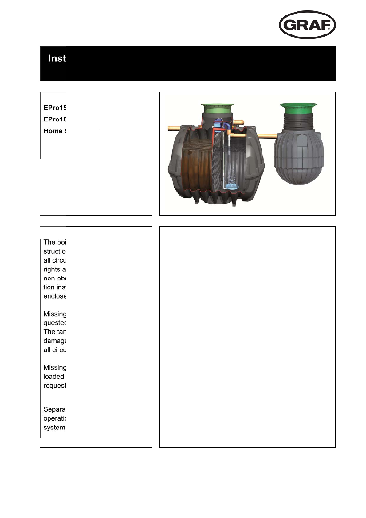
Graf EPro Series, EPro15 Three, EPro15 Two, EPro15 One, EPro15 Three +O Installation Instruction
Page 1
a
n
c
y
e
A
n
S
n
n
m
c
s
a
R
o
n
c
u
A
y
o
s
e
r
r
n
o
a
-
f
b
C
12345
6
7
E
m
s
m
A
b
A
b
s
a
c
h
s
t
3
425
llatio
Domestic
Commer
ewage S
nts describ
s must be
mstances.
e invalid i
ervance.
ructions a
d in the co
instruction
from us i
k must be
prior to in
mstances.
instru
ial
stems
d in these
observed
ll warrant
the event
eparate in
d manuals
trol cabin
s must be
mediately.
hecked fo
tallation u
tion fo
innder
f
tallaare
t.
e-
any
der
r Graf
syste
ontents
.
.
.
.
.
.
.
Genera
Dimen
Syste
ssem
ssem
Commi
Notes
Pro w
l
ions
design
ly of tank
ly of switc
sioning
stewat
omponent
cabinet
er trea
ment
2
3
4
6
1
2
instruction
n www.gr
ed from G
e instructi
n and mai
supplied in
s can be d
f.info or c
AF AU.
ns for start
tenance o
control ca
wn-
n be
up,
the
inet.
Page 2
G
e
TTh w
i T
csb
t
o
T
t
T
u
e
o
w
t
T
c
e
s
a
t
s
p
t
c
e
a
y
e
e
a
b
o
t
e
r
d
a
v
f
A
a
r
r
o
s
a
p
T
e
h
s
e
l
o
h
e
n
a
(
n
o
h
o
o
s
s
d
e
-
-
d
-
-
1.
neral
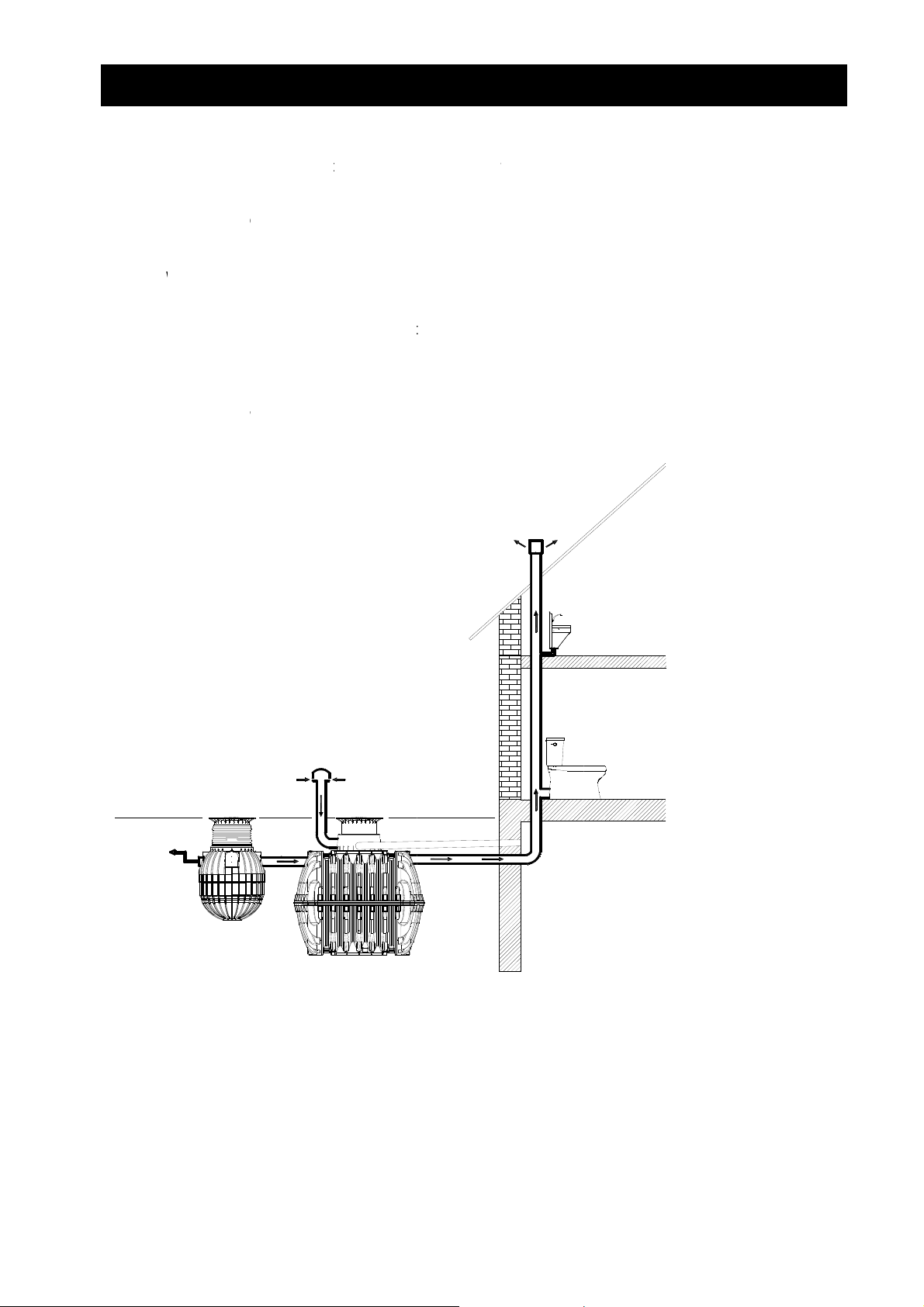
he installa
ion of the
ank must f
1. Gene
llow the di
al
ections in t
e enclosed
installation
instructions
.
hese instr
how to conn
During the
astewater
ings, etc.).
he treatme
ape togeth
uch as to a
ble (more th
ed if neces
ctions also
ct up the in
peration of
reatment s
nt system n
r with gas
llow natural
n 3 m reco
ary.
ontain furth
and outl
le
wastewate
stem shoul
eds ventilat
s without c
entilation (
mended).
er informati
t lines.
r treatment
be situated
ion so that
using any
lue effect).
dditional v
n on the in
ystem som
away from
ir blown int
roblems. T
he vent outl
ntilation lin
tallation co
odour can
iving areas
the tank by
e ventilatio
et height sh
s or ventilat
ditions for t
arise. The l
patio, wind
the compre
lines must
uld be as h
ion opening
e tanks an
cation of th
ws on build
sor, can es
be arrange
igh as possi
must be fit
Ventilati
n with see
age or an o
structed dr
in
2 / 25
Page 3
m
2.
d
5
L
B
t
I
A
2
o
1
2
1
t
i
c
E
6
8
3
1
5
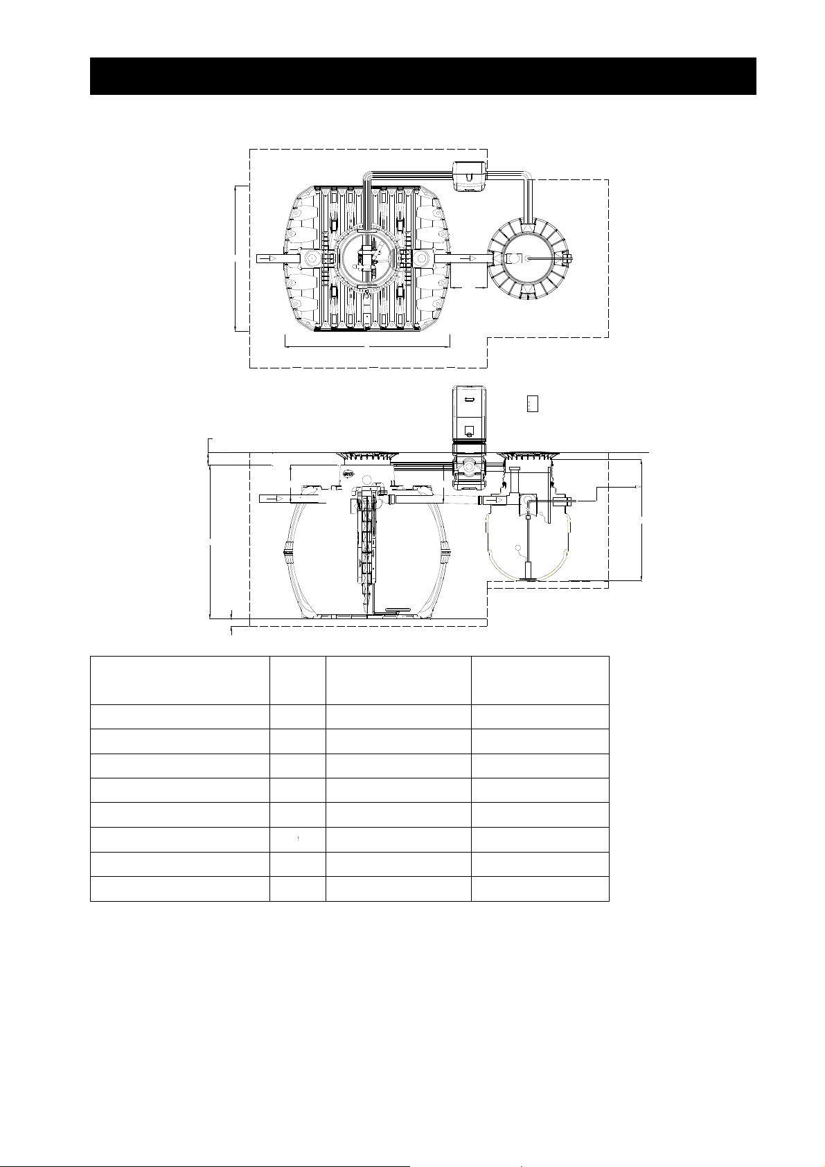
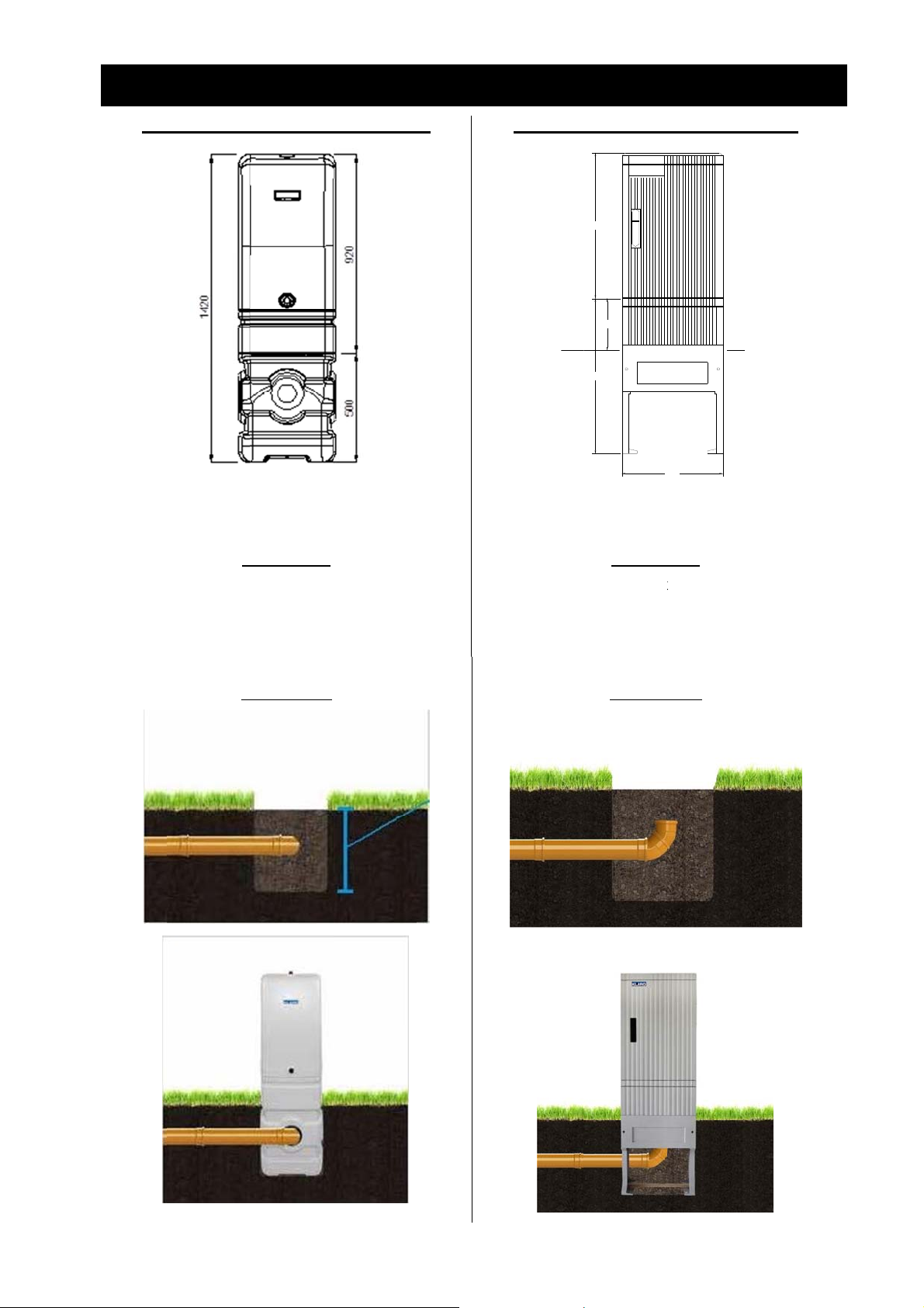
Di
ensions
21
-340
. Dimens
B
L
ons
500
Tank
PE
Max. hy
Length
Width
Height
Inlet
Htot
draulic loa
I
100
Epr
H
ot
15 Domesti
4800 L
10
500 L/d
280 mm
985 mm
O
to irrigation /
infiltration
system
1655
Co
pro18
mercial
500 L
10
1
00 L/d
2
90 mm
2
90 mm
Outlet
95 mm
3 / 25
Page 4
s
3.
C
T
TD RE BF AG O
P
C
s
i
M
a
b
b
H
t
e
p
n
A
i
n
m
A
o
v
F
a
o
t
a
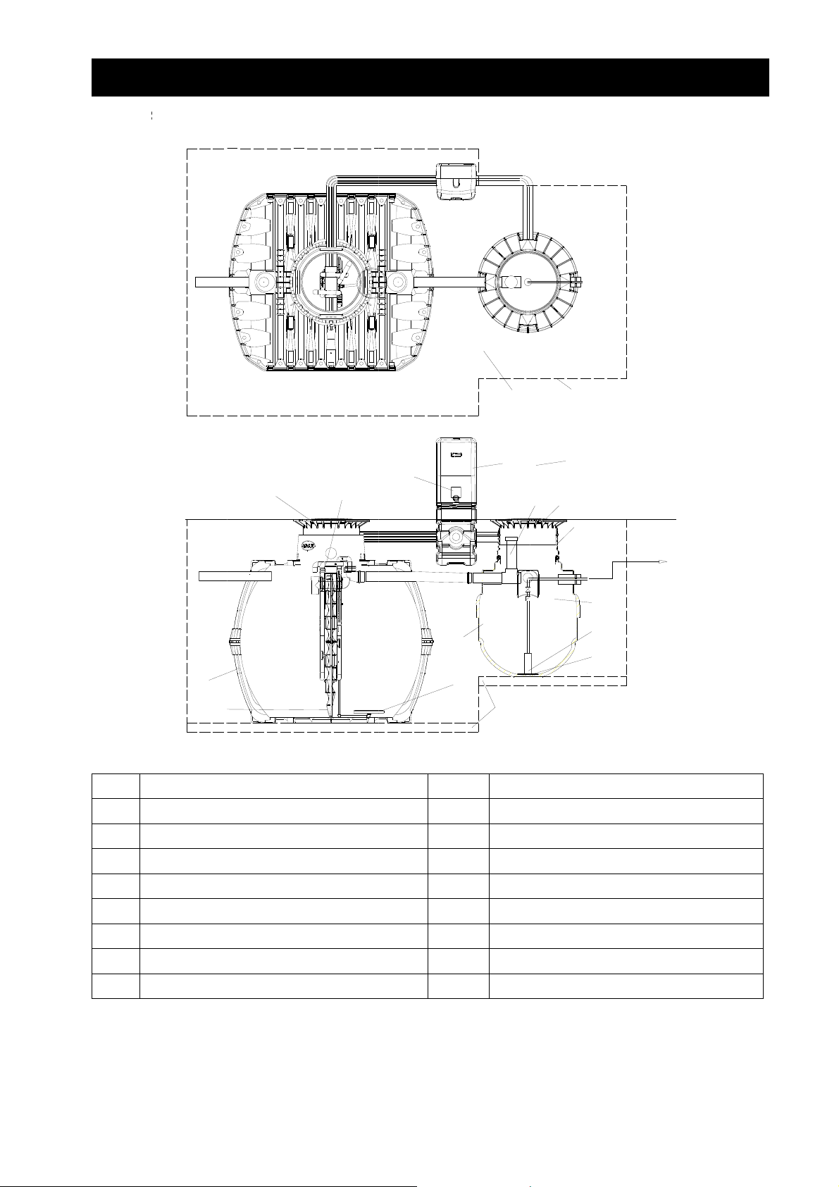
Sy
tem des
gn
3. FSystem d
esign
A
A
arat Tank
Q
O
C
N
E
J
G
P
Irriga
R
M
I
C
D
ion Pump
K
J
L
B
C
H
I
ank Dome
ele Lid Mini
iser Extens
affle
ir Lift / Aer
utdoor Ca
ump Well 9
hlorine Ta
ini
ion
tion
inet Poly
00 l
let Feeder
K
L
M
N
O
P
Q
R
4 / 25
Highl
Pum
Inter
ir D
Cabi
100
ppr
Exca
vel Alarm
Platform
al Alarm Pl
ffusor
et Ventilati
m Compac
ved Backfill
ation
loat
te
n Fan
ed Base M
terial
Page 5
3. System design
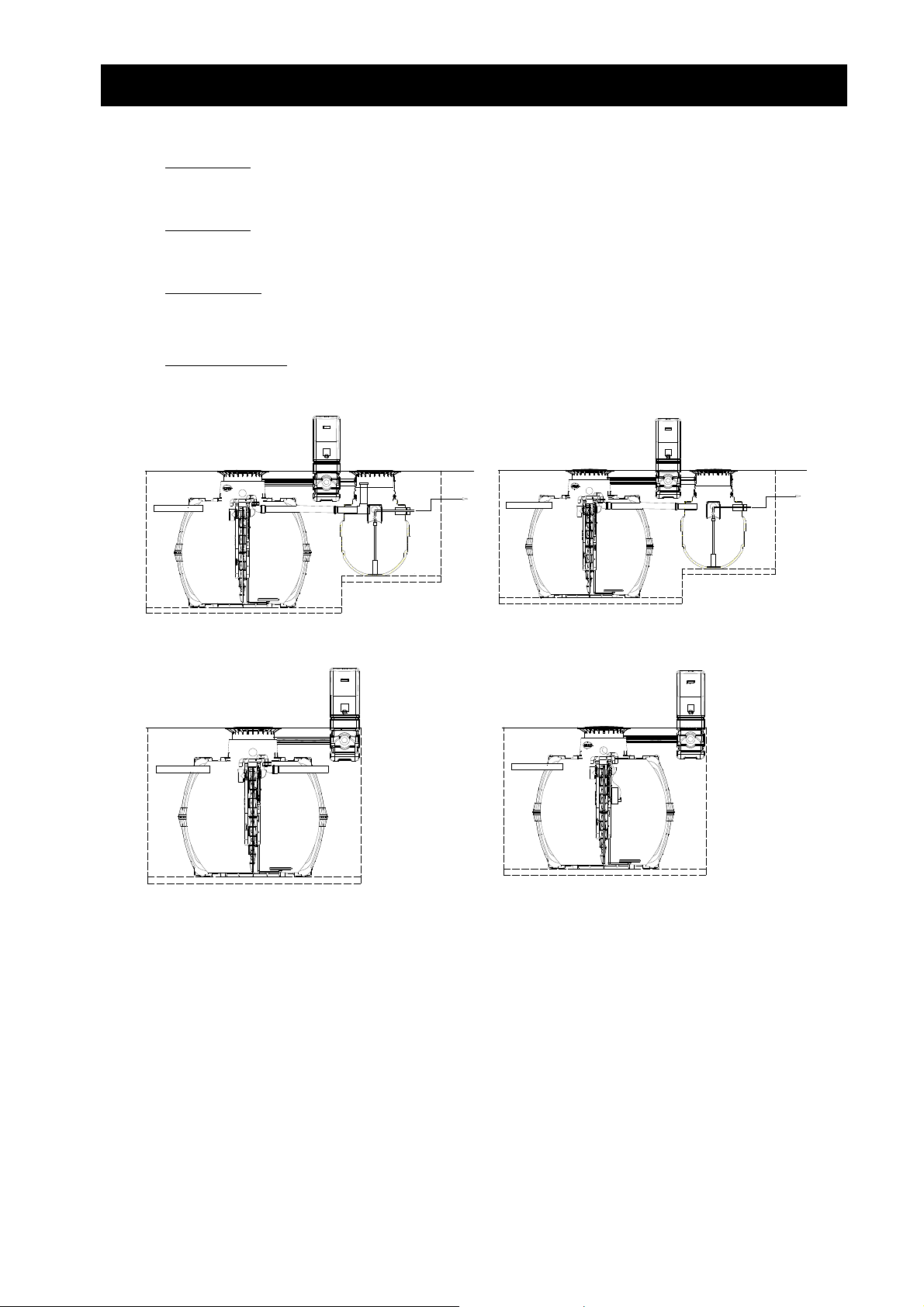
EPro15 systems are available in 4 different versions:
EPro15 One
with chlorination and effluent pump in additional Sapphire 900 L tank
EPro15 Two
with effluent pump in additional Sapphire 900 L tank
EPro15 Three
w/o additional tank. Outflow free slope.
EPro15 Three +O
according to EPro15 Three, but with additional effluent pump inside the treatment plant
Figure 1: Epro15 One
Figure 1: Epro15 Three
Figure 2: Epro15 Two
Figure 2: Epro15 Three +O
5 / 25
Page 6
4.
p
m
s
c
e
c
f
a
o
s
P
o
e
c
f
E
4
m
r
8
V
e
g
n
a
8
x
t
m
b
o
l
s
d
h
a
n
t
k
b
r
e
r
h
w
2cha
E
e
e
f
w
a
m
r
8
t
e
g
n
w
e
6
d
w
r
w
f
0
n
s
s
-
As
sembly o
tank co
. Assem
ponents
ly of tan
compon
nts
Carat S
the top
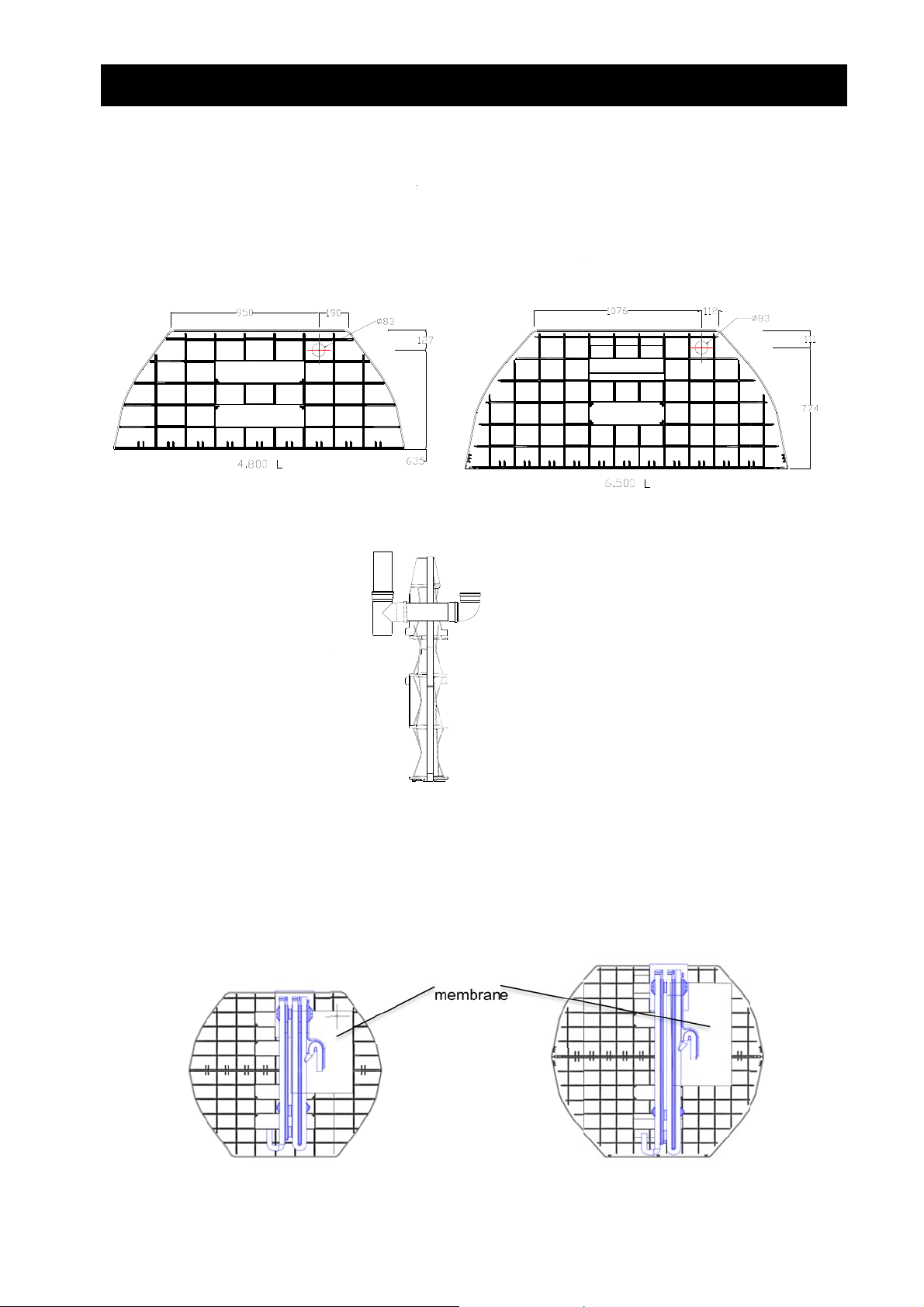
4.1 E
tank has to
art of the b
ergency
Drill hole wit
Put in DN70
be installed
ffle for eme
verflow
h diameter
seal and P
according t
gency overf
3 mm in the
C-fittings a
instruction
low.
top part of
shown in d
manual. Be
affle as sho
awing:
ore installin
n in drawi
the baffle
g:
rill a hole i
4.2 A
The bla
(3.5x13
on the b
tion kit,
The exa
sembling
k PE memb
mm). The c
affle from b
nsure that t
t position o
1s
cha
E-membra
rane suppli
rrespondin
ing drawn i
he outlet sid
the membr
ber
ne
d is screwe
washers s
by the cle
e is on the s
ne is show
on to the b
ould be us
r water lifte
ide where t
in the dra
black P
membran
nd
mber
affle (2
. During the
nd
ch
d. The me
e PE memb
ing.
mber side)
brane prev
subsequent
ane is fitted
ith 6 self-d
nts sludge
mounting o
.
illing screw
hich settle
the installa
EPro1
5 / Carat 4.
with P
sheet 600
00 L
800
6 / 25
EPro1
Commercia
wi
h PE sheet
l / Carat 6.5
600 x 1000
0 L
Page 7
o
o
g
r
E
o
/
n
l
0
0
4
a
x
/
n
d
. Assem
b
t
e
L
k
e
e
e
Cwit
+
6
w
e
w
.
D
e
ly of tan
black PE
membran
compon
nts
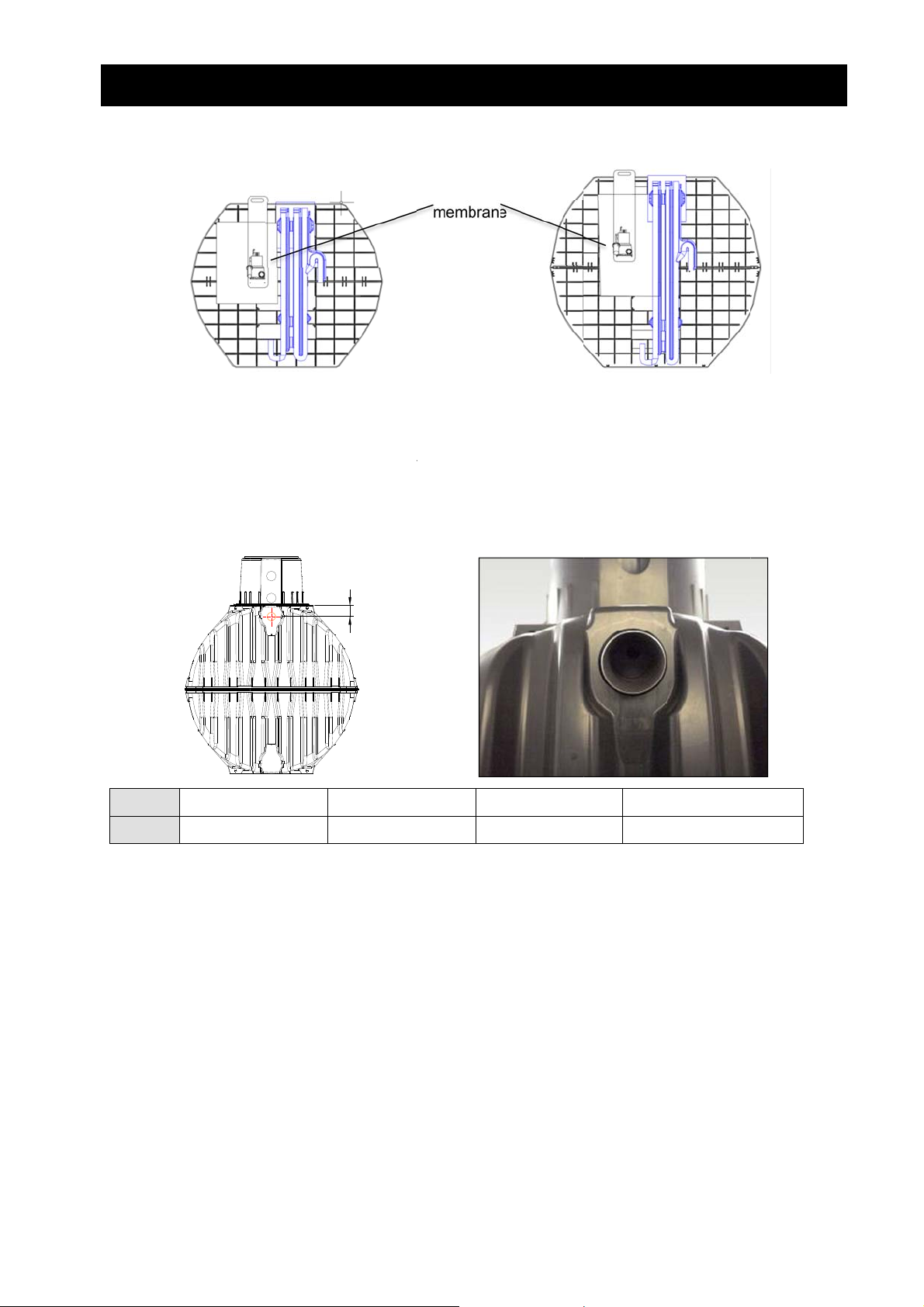
4.3 H
Holes f
seals. A
The hei
Tank
Height
EPro15 Th
with P
les for In-
r DN 100 i
core drill (Ø
ht of the ho
27
14
ee +O / Car
sheet 600
Outflow
let and drai
124 mm) is
e on the en
0 L
mm
t 4.800 L
800
pipes are
required for
faces of th
H
3750
150 m
to be drilled
drilling.
tank can b
L
m
EPro18
in all tanks
found in th
4800 L
230 mm
ommercial
h PE sheet
and fitted
table belo
O / Carat 6
600 x 1000
ith GRAF
.
6500 L
250 mm
500 L
N 100 edg
7 / 25
Page 8
s
5.
n
p
e
n
o
A
e
t
r
e
n
t
i
t
w
a
o
d
e
t
-
n
d
n
s
F
e
T
a
t
x
a
a
d
o
-
In
tallation
set-up ki
5. Ins
tallation
et-up kit
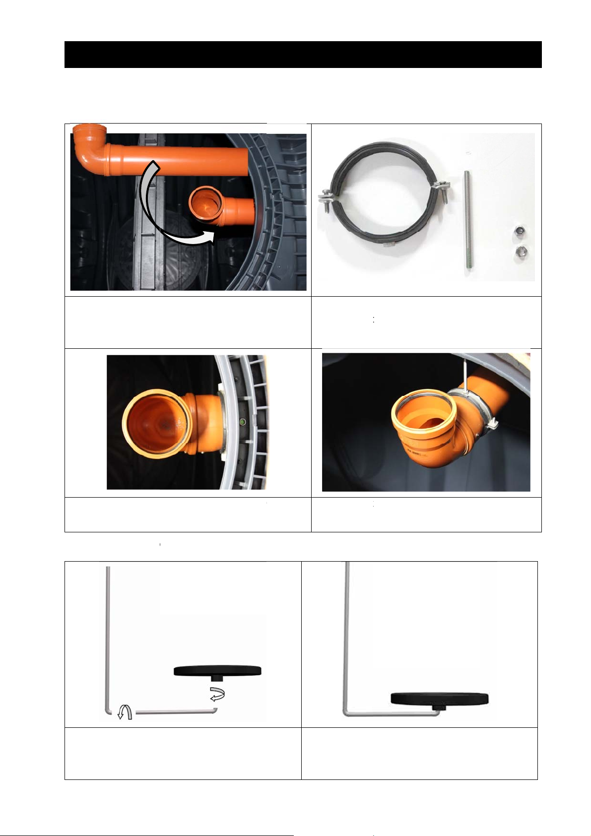
5.1 I
Drain pi
instead
outside.
stallation o
e (pipe DN
orange)) is
f the outflo
110 (pipe
installed fr
pipe
nd bow ca
m the insi
be grey
e to the
or fixing dr
d stud and
in pipe, DN
wo nuts are
100 pipe cl
required.
mp, thread
For fast
through
5.2 I
Screw t
ll conn
Tighten
ning the th
the tank.
stallation a
gether stai
ctions are t
he plastic d
eaded rod,
ration uni
less steel pi
o be sealed
ffuser hand
rill with a 9
es.
using Teflo
tight
mm drill
tape.
he pipe is fi
Do
not allow w
ed by threa
ter to enter
ded bolt an
the ventilati
pipe clamp
n system!
.
8 / 25
Page 9

By Epro
e
n
r
r
w
d
o
a
o
o
h
o
s
t
s
18 Comme
cial, the tw
5. Ins
disc aerat
tallation
rs are
et-up kit
connect
5.3 I
d to the do
stallation o
npipe with
f the aerati
Y-piece.
n unit to t
e set-up ki
The stai
the clea
By snap
nless steel
water lifter.
ping - a clea
ownpipe is
rly audible c
inserted int
lick sounds.
the clamp
9 / 25
provided between the excess sludge lifter and
Page 10

n
k
n
e
i
k
t
s
e
d
p
t
a
e
n
5. Ins
-
b
r
t
s
a
w
t
e
A
e
s
a
u
r
tallation
et-up kit
5.4 I
Set-up
5.5 I
serting/Ins
it has to be
stallation o
allation set
et on the m
f drain (U B
up kit
iddle of the
end)
affle. Disc
erator must
be installed
on side of o
tflow.
The U-b
5.6 F
Set-up
nd is place
xing set-u
it is fixed wi
on the cle
kit and sle
h a screw o
r water lifte
ve connec
the baffle.
. The outflo
ions
of the U-b
ll loos
drilling
nd must le
pipe conne
crews.
d into the d
ctions must
ain pipe.
be fixed with
10 / 25
Page 11

A
e
a
e
n
e
i
m
o
c
e
s
f
5. Ins
p
m
o
u
s
l
s
o
h
e
s
w
m
C
u
c
e
d
r
h
tallation
et-up kit
5.7 A
ir hose con
ection
olored ma
-kit
king at the
EPro set-
ir hos
hose cl
The blu
s have to b
mps accord
hose Ø19
drawn thr
ng to color-
m must be
The gr
The di
for the
ugh the em
oded grom
connected t
en air hose
charge of s
irst critical fl
ty pipe. Co
ets on the
the stainle
is used for t
spended so
ushing surg
ored hoses
et-up kit.
s steel do
e patented
lids is enor
.
have to be
npipe. Ther
air barrier.
ous reduce
onnected a
is no color
nd fixed wit
marking.
11 / 25
Page 12

o
CB H
b
L
m
A
e
F
5. Ins
o
s
n
D
p
s
e
tallation
et-up kit
5.8 C
mponents
of Sapphir
disinfecti
n (as optio
) and pum
-out tank
A
C I
hlorine Ta
igh Water
rrigation Pu
B
let Feeder
evel Alarm
p
loat
Pres
Lip S
E
ure Pipe 40
al DN50
mm
C
D
E
12 / 25
Page 13

o
PB CC MD A
s
f
o
K
h
m
s
d
a
o
t
a
d
b
m
.
w
n
n
e
o
A
m
r
a
g
e
e
b
6.
As
sembly o
switch c
6. Asse
binet
bly of s
itch cabi
et
6.1 C
mponents
A
B
C
D
G
F
E
A
6.2 A
iston Air C
ontrol Unit
anifold wit
uxiliar Alar
sembly an
Find proper
o Clo
o Sha
mpressor
L24plus
Step Motor
Unit
d installati
location for
e to the tre
y as possi
Valves
n
he cabinet:
tment tanks
le
E
F
G
. Mind given
13 / 25
Cooli
Pow
Rem
lar
length of ai
g Fan
r Supply
te Alarm Pl
LED (not fi
hoses (5 m
te
ured)
ter) and ca
les
Page 14
t
E
h
C
t
0
0
6. Asse
m
1
w
n
a
b
i
L
WDep
P
c
i
x
x
5
m
o
e
5
a
-
bly of s
itch cabi
et
Graf plastic ex
erior cabin
xcavations:
et for EPro
5
Plastic c
Assem
accord
binet for E
845
300
900
le bottom p
ng to instru
Excavat
ro18 Com
Inst
600
85
art and fix t
tions includ
ions:
ercial
llation depth
640
top part
d
Lengt
Width
Depth
approx. 40
approx. 450
approx. 50
onduit pipe:
mm
mm
mm
ength appro
idth appro
th approx 6
x 585 mm
315 mm
00–640 mm
Conduit
pipe:
14 / 25
Page 15

Gr
a
a
u p
i
Saa
t
l
t
c
r
a
c
n
h
S
n
a
a
e
t
w
r
d
h
U
m
1
r
n
c
y
A
s
d
w
c
m
m
a
n
a
g
t
a
h
g
e
C
b
P
c
n
e
e
g
d
(
d
r
r
n
m
e
e
m
7
o
e
e
o
d
t
l
f plastic ex
erior cabin
E
ectric cable:
6. Asse
et for EPro
bly of s
5
itch cabi
Plastic c
Can
et
binet for E
Electric
o directly i
ro18 Com
able:
to the cabin
ercial
Illustr
tion only: M
Elec
Make sure
upright befo
Use only m
prevent the
ust comply
rical standa
Filling up:
abinet stan
e filling up t
terial that is
abinet from
ith all Aust
ds
s levelled a
e pit
free from ro
damage
alian
d
k to
through op
Make
uprigh
Filling
filling
granul
soil w
in lon
sure cabin
before fillin
up the insi
granulate
run. The g
Filling
te reduces
ich can lea
n bottom
up:
t stands l
up the pit
e of botto
GRAF 10
humidity c
to corriosi
anulate do
velled and
part with
607). The
ming from
on damage
s not need
6.3 A
r hose con
Pull the air
eal the co
nd causing
lso the oth
ection
oses throug
duit pipe to
corrosion.
r end (tank
h the condui
prevent an
se one GR
ide) of con
t pipe (100
gases fro
F sealing c
uit pipe.
to be r
m DWV PV
transfering
p at the ca
placed.
). Make su
from treatm
inet side a
re hoses ar
ent tank int
t the secon
not kinked.
the cabine
one to sea
15 / 25
Page 16

h
h
C
e
C
a
s
n
s
m
)
e
b
(
6. Asse
m
s
u
o
w
s
m
s
h
c
d
u
a
h
n
s
a
n
m
3
3
h
a
bly of s
itch cabi
et
Insert t
cap
Cut off t
.
e hoses fro
e end of th
m the thin
hose to re
ide of the
ove this pl
ealing Pu
of
g. Pu
tig
h the hose
aterial rem
h the seali
tly.
through th
ins stuck in
g cap into t
e thin top l
the end of t
e conduit pi
yer. A plug
he hose.
e to seal it
onnect the
Charging
Aeration (
Dischargi
Sludge ret
hoses at bo
ir lifter (red
tainless ste
g air lifter (
urn air lifter
th ends acc
l)
lack)
white)
rding their
re
bl
bl
w
16 / 25
olour code:
hose, 13m
e hose, 19
ck hose, 1
ite hose, 1
m
m
mm
mm
Page 17

S
PC PD RE E
A C C
C “
C
n
t
t
p
A
a
C
y
C
g
C
h
“
C
t
e
K
t
n
m
k
s
n
e
n
6. Asse
m
d
h
r
m
n
w
E
p
o
n
t
s
n
A
s
m
p
l
5
u
a
r
n
A
bly of s
itch cabi
et
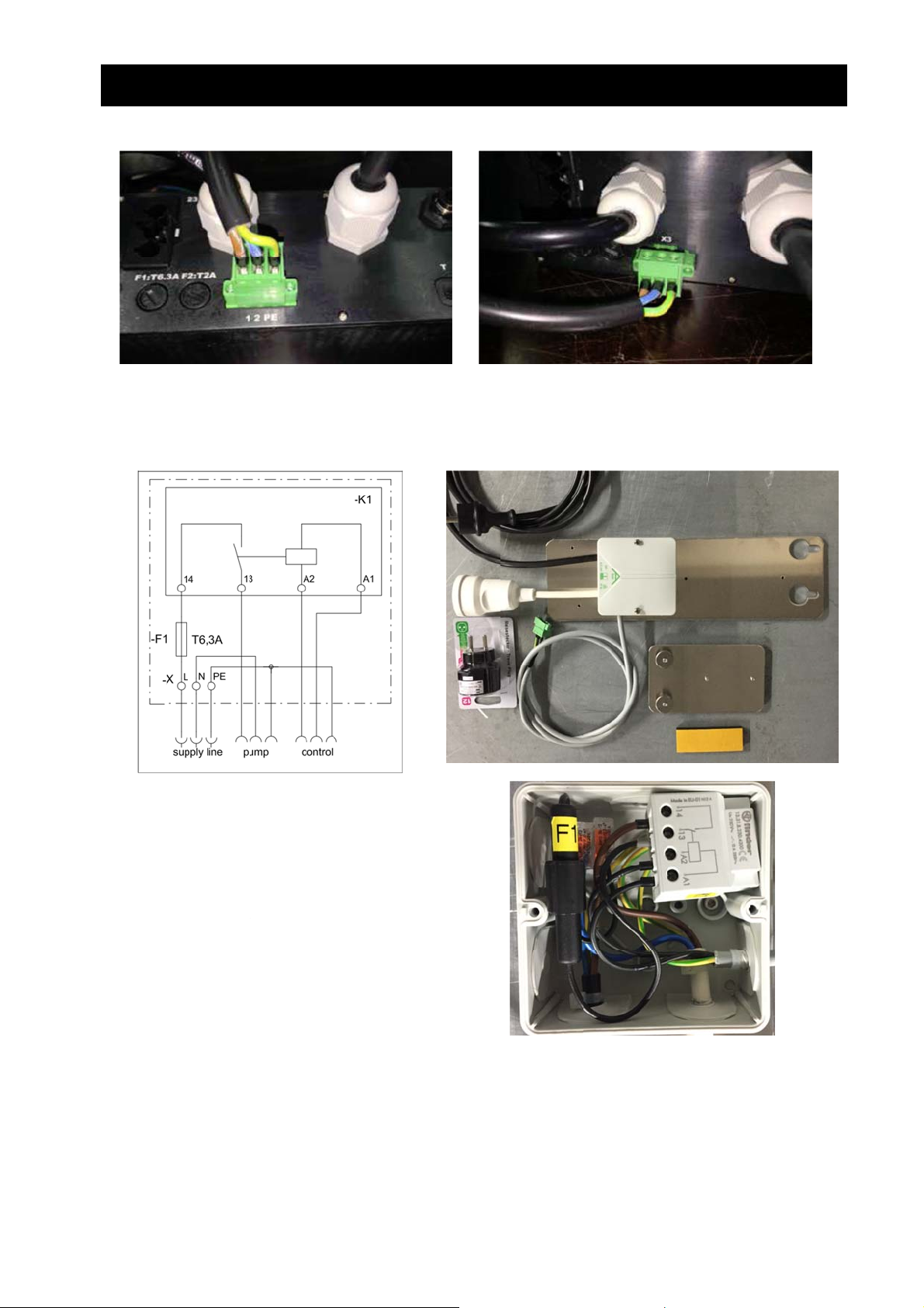
6.4 A
I
H
uxiliary co
troller
A
B
ystem Faul
ower outpu
ower Input
emote Out
ffluent High
uxiliary Al
Pump Run”
G
onnect “S
onnect irri
onnect hig
onnect Ex
F
E
Input from
for irrigatio
ut for Alar
Level / wor
rm Unit mu
stem Fault I
ation pump
-water-leve
(H) shall be
ernal Alarm
D
L24plus
pump
Plate
ing for float
t be installe
put” (A) wit
to “Power O
l / pump wo
set on maxi
Plate to “Re
F
G
H
I
switch
inside the
h alarm out
utput” (B)
king level fl
mum (10 mi
mote Outpu
C
Work
cce
alar
Pum
Statu
Pro Contro
ut plug “X1.
at (E))
)
” (D)
load (option
sory Fault
input)
Run, set to
LEDs
Cabinet
” of KL24pl
B
for addition
(option fo
10 min
s control u
l float)
additional
it
Put the Pow
r Plug (C) i
to the cabi
ets’ power
17 / 25
upply
Page 18

T
a
T
b T
c
a
b
o
T
t
n
c
a
m
6. Asse
m
l
e
w
w
J
w
b
r
J
n
o
s
J
b
w
d
o
bly of s
2
itch cabi
et
he 2 core
void possi
Install Rem
o activate
before mou
front
onnecting
le interferen
te Alarm Pl
he alarm,
ting alarm p
Remote a
able should
ce
te at a plac
ove the Po
late to the
larm plate
be run in a
where ope
er Bridge “
all
ack
separate c
ator can ea
2” on the
nduit to the
ily hear and
ack from on
system po
see it
e pin to bri
er supply t
ge two pins
,
18 / 25
Page 19

e
7.
e
g
6
l
o
h
1
r
X
e
s
r
o
4
e
r
i
4
u
m
w
p
f
f
Cl
ar Water
b
affle height
7. C
Pump M
ear Wate
dule (as
Pump M
ption)
odule (as
option)
7.1 S
480 mm
560 mm
lect the ri
+ XX
min. l
float
Conc
Carat
Carat
ht clip for t
mm
vel when
witch off
ete, 10 EP
4800, 10 EP
6500, 10 EP
e pump
The b
the sw
ackets sho
tch-off point
ld be set
of the pum
ith due con
used.
sideration o
19 / 25
157-162 m
4 pipe cl
ips: 100-10
mm • 108-
16 mm • 12
-132 mm •
Page 20

t
e
7. C
l
r
ear Wate
Pump M
odule (as option)
7.2 M
ounting th
brackets
7.3 S
rain relief
20 / 25
Page 21

o
n
a
n
d
7. C
l
u
r
i
ear Wate
Pump M
odule (as option)
7.4 L
wer pump
socket and
clip mount
ng
7.5 I
The cle
stallation i
r water mo
the tank
ule is hung
p on the pa
rtition baffle.
21 / 25
Page 22
l
t
o
l
s
n
u
e
e
o
n
m
w
n
d
g
n
T
n
7. C
l
r
A
b
r
u
c
p
o
w
U
r
r
o
r
n
o
3
e
u
h
t
d
n
r
h
m
y
A
A
g
ear Wate
Pump M
odule (as
option)
7.6 E
Pumps
connect
7.7 E
ectrical co
hat takes
r and scre
ectrical co
nection fo
aximum 2
ed on with
nection fo
clear wate
mpere can
oth screws
clear wate
pump up
connected
n the left a
pump mo
o 2A
irectly to t
d on the rig
e than 2A (
e control s
t.
aximum 6
stem using
)
a 3-pin plu
Pump i
using a
pulled o
is plugg
and scr
and on
needs t
cabinet.
connecte
EU-AU ad
t with the
d directly i
wed on wit
the right.
plugged i
to the pl
aptor. The
reen 3-pin
to the contr
h both scre
he black E
to the free
g-in coupli
able which
lug connect
l system (X
s on the l
power pl
socket of t
g
is
or
3)
ft
g
e
22 / 25
Page 23

7. Clear Water Pump Module (as option)
7.8 Programming the control unit
For running a submersible clear water pump, we are using the control unit's UV power outlet and UV
setting.
Program settings in the Service Menu need to be changed for T09, T10, T11 and UV:
Time Explanation Valve
EPro15 EPro18 Com.
T 1 [min] charging 1
T 2 [min]
T 3 [min]
T 4 [sek]
Deniphase
off
on
2
T 5 [min] Aeration
T 6 [min] on
2
T 7 [min] off
T 8 [min] Sedimentation
T 9 [min] Discharging
T 10 [min] on
3
12 12
0 0
T 11 [min] off 1 1
T 12 [sec] Sludge return 4
T 13 [min] break of cycle - off
T 14 [min] break of cycle- on
T 15 [min] Holiday - on
T 16 [min] Holiday - off
T 17 [min] total cycle time
T 18 [min] total aeration time
T 19 [min] Total running time
Duty cycle UV module
2
shall be less than 360!
12 12
T-settings can be found in menu "duration period setup" and UV-settings in "UV-light unit setup".
For extending the standard pump time, enlarge T 09 and UV-time. Caution: Check T 17. Total cycle time must be less
than 360 minutes!
Software Jumper
Set Software-Jumper 8 = 0.
The clear water pump can be operated in manual mode, see menu - UV module.
23 / 25
Page 24

C
o
Y C
w
t
A Gbj T
t
n
s
Y
p
C
c
p
e
w
r
t
g
m
A
G
u
j
e
T
t
y
e
r
o
f
a
r
o
a
e
d
a
C
p
r
1
w
n
o
“
t
h
e
i
l
r
x
n
n
c
e
e
Y
t
n
u
c
t
o
n
h
u
e
,
d
e
a
e
s
f
c
c
u
o
a
e
”
u
a
o
p
t
o
T
u
f
a
5
f
g
n
n
e
.
t
.
8.
mmissio
Finish all in
Fill up the tr
ing
tallation wo
eatment tan
8.
k described
with fresh
ommiss
in this instal
water; othe
oning
ation instru
wise no tes
tion
run and sy
tem check
re possible
.
ou can sto
onnect ele
Plug in the
Plug in pow
ill then sta
he system
ESC two ti
rea.
o to “man
by pressing
umping to t
Finally leav
he cabinet
reatment c
Find more
filling up w
tric cable t
ower plug o
r plug com
t automatic
oes on ala
es. Then y
al operation
“1” button
he next. Se
“manual op
is then rea
cle
information
hen water le
Power Sup
the Auxilia
ming from c
lly. At Epro
m and sho
u should e
” in Operati
nd off by
if all air lif
eration” wit
y to operat
in “Start-up
vel is appro
ply – double
y Alarm Co
ontrol unit i
8 Commer
s “Set Dat
ter the corr
n Area and
0” button.
s are worki
ESC.
and will co
, operation
. 20 cm bel
socket (lice
troller into t
to Power s
ial, you hav
and Time”
ct date an
test all valv
ou should
g and aer
nt down in
and maint
w bottom o
sed electri
e GPO.
pply. The
to turn mai
you can q
time in the
s and the c
lways turn
tion on valv
“cyclepause
nance man
outlet pipe
an only!)
ontrol unit
n switch to
it the alarm
control uni
oling fan.
the previo
e 2 shows
” until the st
ual” inside
f an Epro1
osition “I”. I
by pressin
s’ Operatio
urn them o
s off befor
ine bubbles
rt of its firs
the cabinet
Especially r
ad the dos
nd don’ts.
24 / 25
Page 25

tes
o
s
o
9. Note
25 / 25
www.graf.inf
2017-07
 Loading...