

Graf CARAT XXL Series, CARAT XXL 16.000 litres, CARAT XXL 122 000 litres Installation/assembly And Maintenance Instructions
Page 1
CARAT XXL Löschwasserbehälter
DE
Einbau-/ Montage-/ und Wartungsanleitung für
Graf CARAT XXL Löschwasserbehälter
>> Seite 1-14
EN
Installation/ assembly and maintenance instructions for
Graf Carat XXL extinguishing water tanks
>> Page 15-28
FR
Notice d’installation et d’entretien Carat XXL GRAF
Réserve Incendie
>> Page 29-42
ES
Instrucciones de instalación / montaje y mantenimiento
para GRAF Carat XXL depósito de agua para extinción
de incendios
>> Page 42-56
Page 2
Einbau-/ Montage-/ und Wartungsanleitung für
GRAF Carat XXL Löschwasserbehälter
16.000* - 122.000* Liter
Best.-Nr.: 380050 - 380071
*Bitte beachten Sie, dass das
Nutzvolumen um bis zu 10%
unter dem Behälter-Gesamt-
volumen liegen kann.
mail@graf.info
www.graf.info
Die in dieser Anleitung beschriebenen Punkte sind unbedingt zu
beachten. Bei Nichtbeachtung erlischt jeglicher Garantieanspruch.
Für alle über GRAF bezogenen
Zusatzartikel erhalten Sie separate
in der Transportverpackung beiliegende Einbauanleitungen.
Eine Überprüfung der Behälter,
sowie dessen LöschwasserAusbaukomponenten auf eventuelle Beschädigungen, hat unbedingt
vor dem Versetzen in die Baugrube zu erfolgen.
Fehlende Anleitungen können Sie
unter www.graf.info downloaden
oder bei GRAF anfordern.
Inhaltsübersicht
1. ALLGEMEINE HINWEISE 2
1.1 Sicherheit 2
1.2 Kennzeichnungspflicht 2
Abnahme 2
1.3
2. EINBAUBEDINGUNGEN 3
3. TECHNISCHE DATEN 4
4. AUFBAU TANK 7
5. EINBAU UND MONTAGE 7
5.1 Einbauort 8
5.2 Überdeckungshöhen 8
5.3 Baugrund 8
5.4 Baugrube 8
5.5 Einsetzen und Verfüllen 10
5.6 Anschlüsse legen 10
6. TANKDOM UND TELESKOP-DOMSCHACHT
MONTIEREN 11
6.1 Tankdom montieren 11
6.2 Teleskop-Domschacht montieren 11
6.3 Teleskop-Domschacht begehbar 11
6.4 Teleskop-Domschacht PKW-befahrbar 12
6.5 Teleskop-Domschacht LKW-befahrbar 12
6.6 Montage Zwischenstück 12
7. LÖSCHWASSER AUSBAUKOMPONENTEN 13
Saugarmatur 13
7.1
7.2 Entlüftung 13
Beschilderung 13
7.3
7.4 Einstiegsleiter 13
8. INSPEKTION UND WARTUNG 14
1 / 56
Page 3

mail@graf.info
www.graf.info
1. Allgemeine Hinweise
1.1 Sicherheit
Bei sämtlichen Arbeiten sind die einschlägigen Unfallverhütungsvorschriften nach BGV C22 zu beachten.
Besonders bei Begehung der Behälter ist eine 2. Person zur Absicherung erforderlich.
Des Weiteren sind bei Einbau, Montage, Wartung, Reparatur usw.
die in Frage kommenden Vorschriften und Normen zu berücksichtigen. Hinweise hierzu finden Sie in den dazugehörigen Abschnitten dieser Anleitung.
Bei sämtlichen Arbeiten an der Anlage bzw. Anlagenteilen ist immer die Gesamtanlage außer Betrieb zu setzen und gegen unbefugtes Wiedereinschalten zu sichern.
Die Behälterabdeckung ist stets, außer bei Arbeiten im Behälter,
verschlossen zu halten, ansonsten besteht höchste Unfallgefahr.
Der bei Anlieferung montierte Regenschutz ist nur eine Transportverpackung, nicht begehbar und nicht kindersicher, er muss umgehend nach Anlieferung gegen eine geeignete, bauseits zu stellende
Abdeckung ausgetauscht werden.
Die Firma GRAF bietet ein umfangreiches Sortiment an Zubehörteilen, die alle aufeinander abgestimmt sind und zu kompletten Systemen ausgebaut werden können. Die
Verwendung, nicht von GRAF freigegebener Zubehörteile führt zu einem Ausschluss der Gewährleistung/Garantie.
1.2 Kennzeichnungspflicht
Der Pfosten mit Halter für das Hinweisschild "Löschwasserentnahmestelle", zur direkten Befestigung am
Saugrohr, ist bereits im Lieferumfang enthalten. Das entsprechende Hinweisschild nach DIN 4066-B2 mit
der jeweiligen Löschwasser-Inhaltsangabe ist bauseits zu stellen und dauerhaft sowie gut sichtbar am
Halter zu befestigen.
1.3 Abnahme
Jeder neu angelegte Löschwasserbehälter ist durch Beauftragte der entsprechenden Behörde abzunehmen und auf Funktion zu überprüfen. Der Nachweis sowie die Berechnung der erforderlichen Löschwassermenge erfolgen über den zuständigen Brandschutz-Sachverständigen. Bitte beachten Sie, dass das
tatsächliche Löschwasser-Nutzvolumen um bis zu 10% unter dem angegebenen BehälterGesamtvolumen liegen kann.
2 / 56
Page 4

2. Einbaubedingungen
Überdeckungshöhen mit Teleskop Domschacht
LKW (Abdeckung nach DIN 3223 - bauseits zu
stellen) im begehbaren Grünbereich 750-1050
mm.
Maximale Überdeckungshöhe mit Zwischenstück und Teleskop-Domschacht LKW (Abdeckung nach DIN 3223 - bauseits zu stellen).
Maximale Überdeckungshöhe 1500 mm.
mail@graf.info
www.graf.info
Teleskop-Domschacht LKW
(Abdeckung nach DIN 3223 -
bauseits zu stellen)
750 - 1050
max. 1500
Überdeckungshöhen mit Teleskop-Domschacht
LKW (Abdeckung nach DIN 3223 - bauseits zu
stellen) im PKW-befahrenen Bereich >800<1500
mm.
Überdeckungshöhen mit Teleskop Domschacht
LKW (Abdeckung nach DIN 3223 - bauseits zu
stellen) im LKW-befahrenen Bereich
>1000<1500 mm.
(Belastung bis max. 40 t)
Die Tanks dürfen nur bedingt ins Grundwasser
eingebaut werden. Ist zu erwarten, dass Grundwasser auch nur gelegentlich höher ansteigt, als
in der nebenstehenden Abbildung gezeigt, ist
dieses durch eine Drainage abzuleiten.
Max.
> 800 < 1500
max. 40 to
max. 8 to
> 1000 < 1500
> 800 < 1500
Max.
Überdeckungshöhen bei Grundwasser
>800<1500 mm.
Es wird empfohlen, generell eine Drainage einzubauen
3 / 56
Page 5
mail@graf.info
Höhe
Tan
k-
Tan
k-
Tan
k-
Tan
k-
www.graf.info
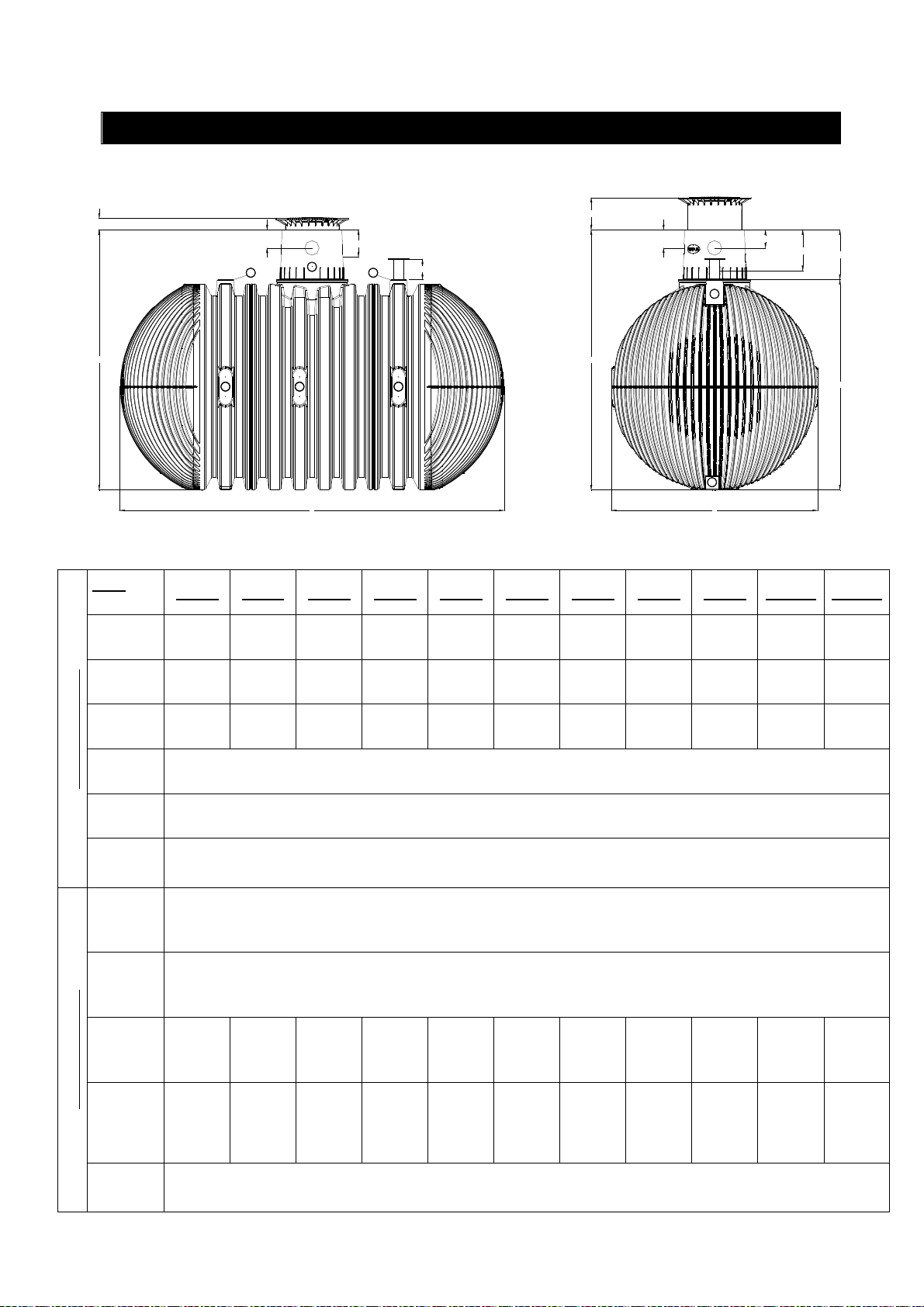
3. Technische Daten
Min. 140
Htot
Tank
(Liter)
Art.-Nr.
Max. 440
220
4 4
3 3 3
330
5
L
220
250
2
Htot
1
B
220
495
610
H
16.000 26.000 36.000 46.000 56.000 66.000 76.000 86.000 96.000 106.000 116.000
380050 380052 380054 380056 380058 380060 380062 380064 380066 380068 380070
Gewicht
(kg)
L (mm)
B (mm)
Technische Daten
H (mm)
total
(mm)
böden
(Unten)
DN100
böden
(Oben)
DN150
zylinder
(Seiten)
DN100
Anschlussflächen
Tankzylinder
(Oben)
DN200
dom
DN150
805 1150 1495 1840 2185 2530 2875 3220 3565 3910 4255
4660 7045 9430 11815 14200 16585 18970 21355 23740 26125 28510
2500
2550
3160
2
2
12 16 20 24 28 32 36 40 44 48 52
2 3 4 5 6 7 8 9 10 11 12
5
4 / 56
Page 6
mail@graf.info
Tankb
ö-
Tankb
ö-
Tankz
y-
Tankzy
l-
Tan
k-
www.graf.info
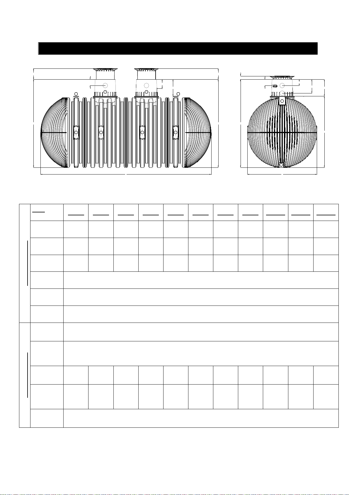
3. Technische Daten
340 (Mini)
Htot
Tank
(Liter)
Art.-Nr.
220
4
3 3
440 (Maxi)
330
5
L
5
3 3
610
4
Htot
140
Htot
220
220
495
610
2
H
1
B
22.000 32.000 42.000 52.000 62.000 72.000 82.000 92.000 102.000 112.000 122.000
380051 380053 380055 380057 380059 380061 380063 380065 380067 380069 380071
Gewicht
(kg)
L (mm)
B (mm)
Technische Daten
H (mm)
Höhe total
(mm)
den (Unten) DN100
den
(Oben)
DN150
linder (Seiten) DN100
inder
Anschlussflächen
(Oben)
DN200
dom
DN150
1015 1360 1705 2050 2395 2740 3085 3430 3775 4120 4465
6145 8530 10915 13300 15685 18070 20455 22840 25225 27610 29995
2500
2550
3160
2
2
16 20 24 28 32 36 40 44 48 52 56
2 3 4 5 6 7 8 9 10 11 12
10
5 / 56
Page 7
mail@graf.info
www.graf.info
3. Technische Daten
C
m³
F
E
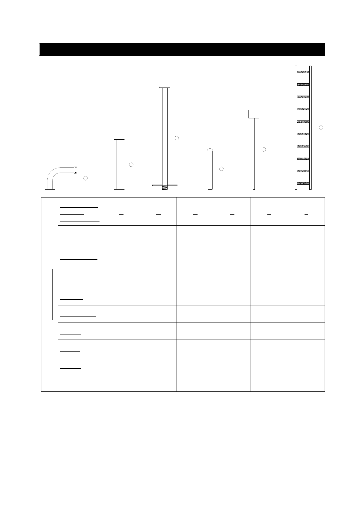
Löschwasser
Ausbaukomponenten
Bezeichnung
Material
Gewicht (kg)
Technische Daten
Ø (mm)
B
A
D
A B C D E F
A-Festkupplung
Sauganschluss mit
für Saugrohr
Verlängerungsstück
Saugkorb
wirbelplatte und
Saugrohr inkl. Anti-
Haube und Sieb
Entlüftungsrohr mit
für Hinweisschild
Pfosten mit Halter
Einstiegsleiter
V2A V2A PE/ V2A V2A V2A Alu
11,5 13,5 13 5,5 5 5
DN 125 DN 125 DN 125 DN 100 - -
L (mm)
B (mm)
H (mm)
- - - -
- - - -
550 1200 2400 1000 2000 2900
6 / 56
Pfosten: 40
Halter: 250
Pfosten: 40
Halter: 200
-
355
Page 8
mail@graf.info
www.graf.info
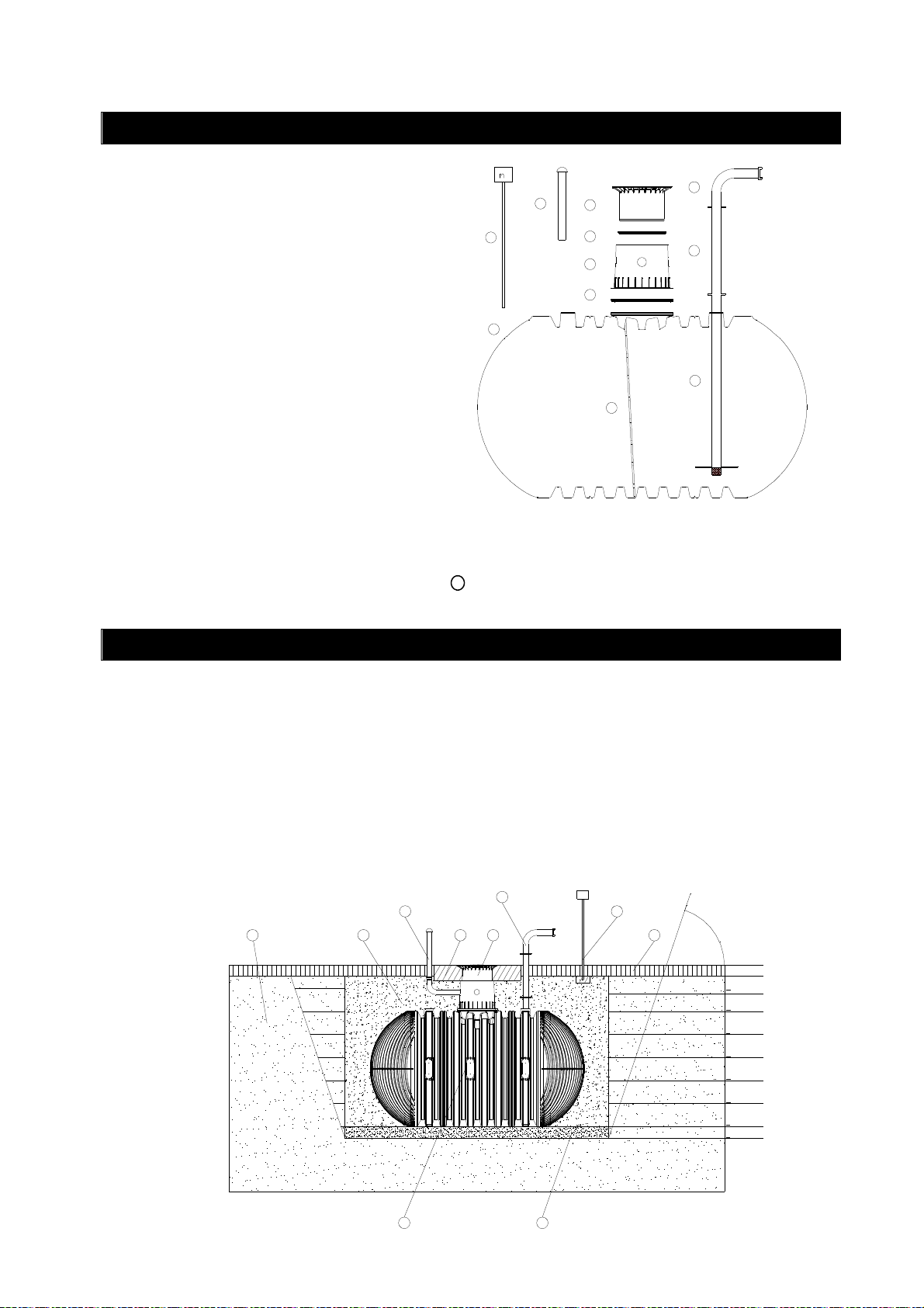
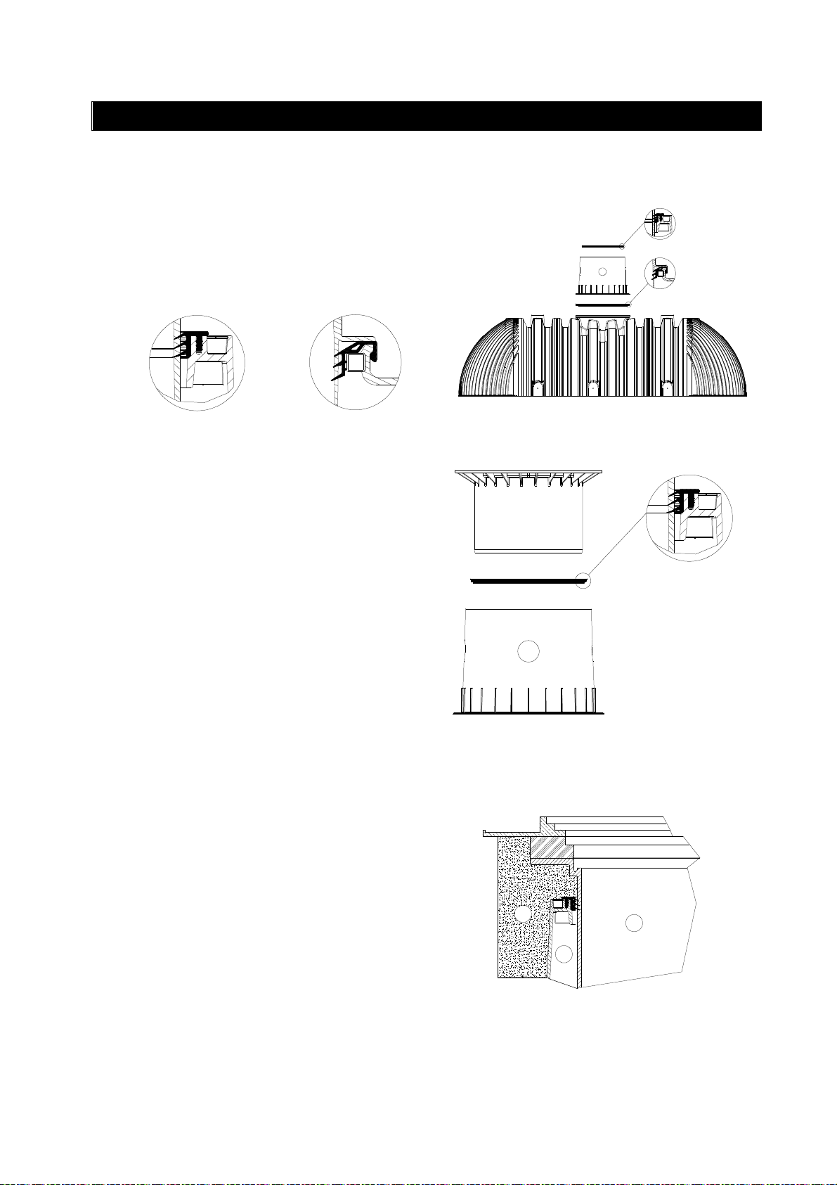
4. Aufbau Tank
Teleskop-Domschacht LKW (Abdeckung
nach DIN 3223 – bauseits zu stellen)
Profildichtung Tankdom/ Teleskop
Tankdom (um 360° drehbar)
Profildichtung Tank/ Tankdom
Carat XXL Löschwasserbehälter
Sauganschluss mit A-Festkupplung nach
DIN 14244
Verlängerungsstück für Saugrohr mit
Flansch DN 125
Saugrohr mit Flansch DN 125 inkl. Anti-
wirbelplatte und Saugkorb
Entlüftungsrohr DN 100 mit Haube und
Sieb
³
9
10
5
Pfosten mit Halter für bauseitiges Hinweisschild
"Löschwasserentnahmestelle" nach DIN 4066-B2
1
2
3
4
11
6
7
8
Einstiegsleiter inkl. Befestigungssatz zur Montage
11
im Tankdom
Erdreich
Teleskop-Domschacht LKW (Abdeckung
nach DIN 3223 – bauseits zu stellen)
verdichteter Unterbau
Umhüllung
(Rundkornkies max. Körnung 8/16)
Deckschicht
ß nach DIN 4124
1 4
5. Einbau und Montage
Carat XXL Löschwasserbehälter
Betonschicht bei PKW-/ LKW-befahrenen Flächen
Sauganschluss mit A-Festkupplung nach DIN 14244
Entlüftungsrohr mit Haube und Sieb
Pfosten mit Halter für bauseitiges Hinweisschild
nach DIN 4066-B2
8
2
7
m³
109
5
ß
> 100 mm
< 300 mm
< 300 mm
< 300 mm
< 300 mm
< 300 mm
< 300 mm
< 300 mm
> 150 mm
6
7 / 56
3
Page 9

mail@graf.info
www.graf.info
5. Einbau und Montage
5.1 Einbauort
Die Löschwasserentnahmestelle muss sich außerhalb des Trümmerschattens von Gebäuden befinden.
Zur Entnahmestelle ist von der öffentlichen Verkehrsfläche eine Feuerwehrzufahrt zu erstellen. Die Zufahrt muss den Anforderungen nach DIN 12090 entsprechen, sofern landesrechtliche Vorgaben dem
nicht entgegenstehen. Ausnahmen bedürfen der Absprache mit der für den Brandschutz zuständigen
Stelle.
5.2 Überdeckungshöhen
Bitte beachten Sie, dass sich der im standardisierten Lieferumfang enthaltene Teleskop-Domschacht
LKW (Abdeckung nach DIN 3223 – bauseits zu stellen) auf eine generelle Überdeckungshöhe von 7501050 mm bezieht. Sollten hiervon abweichende Erdüberdeckungen erforderlich sein, müssen entsprechende Zwischenstücke zur Verlängerung mitbestellt werden (Achtung: max. Erdüberdeckung 1500 mm).
Je nach Einbau bzw. endgültiger Fertighöhe des Löschwasser-Sauganschlusses, muss das mitgelieferte
Saugrohr-Zwischenstück individuell angepasst bzw. separat, in gewünschter Sonderlänge bestellt werden. Bei Positionierung bitte DIN 14244 beachten.
5.3 Baugrund
Vor der Installation müssen folgende Punkte unbedingt abgeklärt werden:
• Die bautechnische Eignung des Bodens nach DIN 18196
• Maximal auftretende Grundwasserstände bzw. Sickerfähigkeit des Untergrundes
• Auftretende Belastungsarten, z.B. Verkehrslasten
Zur Bestimmung der bodenphysikalischen Gegebenheiten sollte ein Bodengutachten beim örtlichen Bauamt angefordert werden.
5.4 Baugrube
Damit ausreichend Arbeitsraum vorhanden ist, muss die Grundfläche der Baugrube die Behältermaße auf
jeder Seite um 500 mm überragen, der Abstand zu festen Bauwerken muss mind. 1000 mm betragen.
Die Böschung ist nach DIN 4124 anzulegen. Der Baugrund muss waagerecht und eben sein sowie eine
ausreichende Tragfähigkeit gewährleisten.
Die Tiefe der Grube muss so bemessen sein, dass die max. Erdüberdeckung (siehe Punkt 2 - Einbaubedingungen) über dem Behälter nicht überschritten wird. Für die ganzjährige Nutzung der Anlage ist eine
Installation des Behälters und der wasserführenden Anlagenteile im frostfreien Bereich notwendig. In der
Regel liegt die frostfreie Tiefe bei ca. 600-800 mm, genaue Angaben hierzu erhalten Sie bei der zuständigen Behörde.
Als Unterbau wird eine Schicht verdichteter Rundkornkies (Körnung 8/16, Dicke ca. 150-200 mm) aufgetragen.
8 / 56
Page 10
mail@graf.info
www.graf.info
5. Einbau und Montage
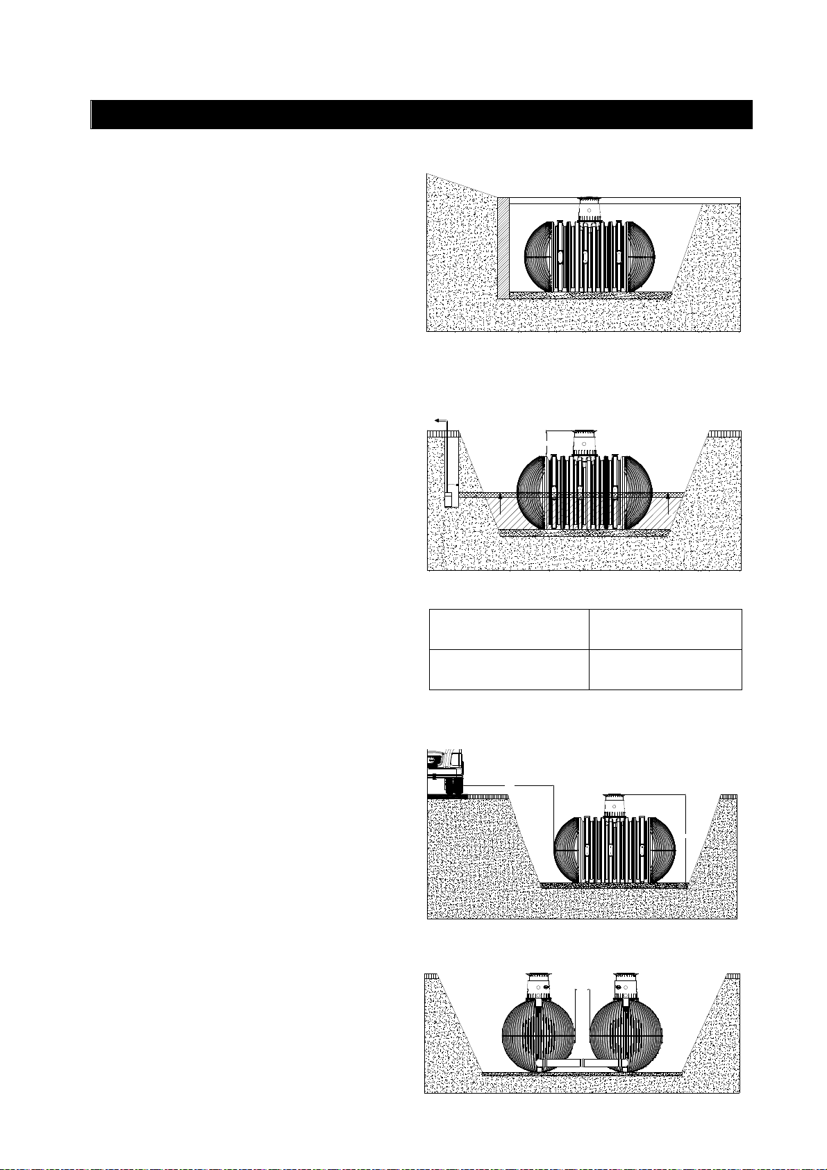
5.4.1 Hanglage, Böschung etc.
Beim Einbau des Behälters in unmittelbarer Nähe
(< 5 m) eines Hanges, Erdhügels oder einer Böschung muss eine statisch berechnete Stützmauer zur Aufnahme des Erddrucks errichtet
werden. Die Mauer muss die Behältermaße um
mind. 500 mm in alle Richtungen überragen und
einen Mindestabstand von 1000 mm zum Behälter haben.
5.4.2 Grundwasser und bindige (wasserundurchlässige)
Bei gelegentlich auftretendem Grundwasser und
bindigen, wasserundurchlässigen Böden
(z.B. Lehm) ist für eine ausreichende Ableitung
(Drainage) des Grund- bzw. Sickerwassers zu
sorgen, so dass die Behälter nie tiefer als in der
Tabelle angegeben im Grundwasser stehen. Ggf.
muss die Drainageleitung in einem senkrecht
eingebauten DN 300 Rohr enden, in dem eine
Tauchdruckpumpe eingelassen ist, die das überschüssige Wasser abpumpt. Die Pumpe ist regelmäßig zu überprüfen. Ist zu erwarten, dass die
Behälter tiefer eintauchen ist in jedem Fall für
eine ausreichende Ableitung zu sorgen.
Überdeckungshöhen bei Grundwasser
>800<1500 mm.
Wir empfehlen generell die Verlegung einer Drainageleitung, da bei längeren Regenereignissen
der Grundwasserstand unvorhergesehen ansteigen kann.
5.4.3 Installation neben befahrenen Flächen
Werden die Erdtanks neben Verkehrsflächen
installiert, die mit schweren Fahrzeugen über 40 t
befahren werden, entspricht der Mindestabstand
zu diesen Flächen mindestens der Grubentiefe.
Böden (z. B. Lehmboden)
> 800 < 1500
Max. Max.
Tankgröße
alle Tankgrößen
Eintauchtiefe
> H
1275 mm
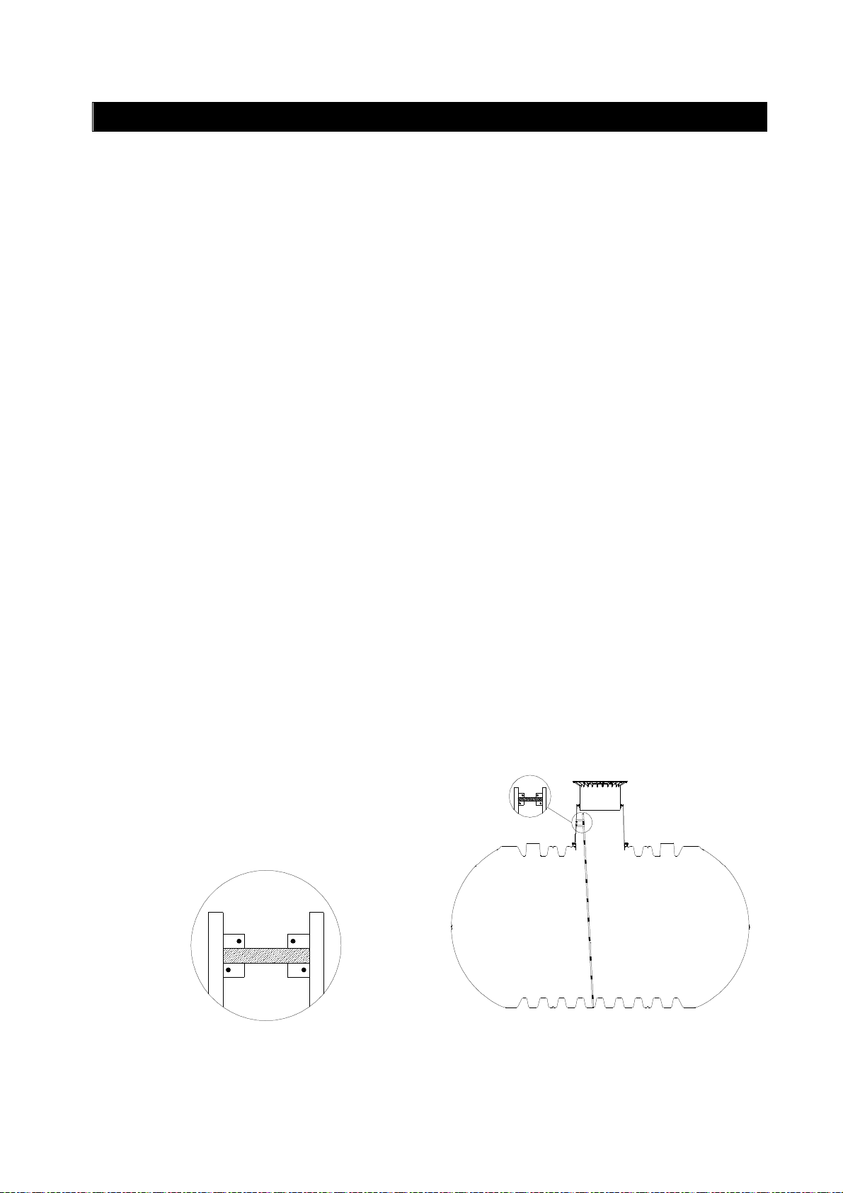
5.4.4 Verbindung mehrerer Behälter
Die Verbindung von zwei oder mehreren Behältern erfolgt über eingeschweißte Rohrstutzen DN
250 (2-facher Nenndurchmesser des Saugrohres). Die Rohrstutzen sind so tief wie möglich am
Behälter anzuordnen. Es ist darauf zu achten,
dass der Abstand zwischen den Erdtanks mind.
600 mm beträgt.
H
> 600
9 / 56
Page 11
mail@graf.info
www.graf.info
5. Einbau und Montage
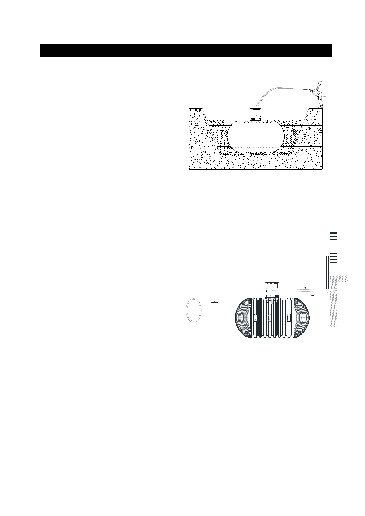
5.5 Einsetzen und Verfüllen
Die Behälter sind stoßfrei mit geeignetem Gerät
in die vorbereitete Baugrube einzubringen.
Vor dem Anfüllen der Behälterumhüllung wird der
Behälter mit ca. 25 cm Wasser gefüllt, danach
wird die Umhüllung (Rundkornkies max. Körnung
8/16) lagenweise in max. 40 cm Schritten bis
Behälteroberkante angefüllt und verdichtet. Die
einzelnen Lagen müssen gut verdichtet werden
(Handstampfer). Beim Verdichten ist eine Beschädigung des Behälters zu vermeiden. Es dürfen auf keinen Fall mechanische Verdichtungsmaschinen eingesetzt werden. Die Umhüllung
muss mind. 500 mm breit sein.
5.6 Anschlüsse legen
n den Löschwasserbehälter darf kein Schmutz-
I
wasser eingeleitet werden.
40 cm
25 cm
Beim Befüllen muss das Wasser zwischen dem
Austritt der Füllleitung und dem maximalen Wasserspiegel des Behälters laut DIN 1988-6 mit der
freien Atmosphäre in Berührung kommen. Zwischen dem maximalen Wasserspiegel und der
Behälterdecke muss ein Luftpolster von mindestens 100 mm eingehalten werden, ggf. ist der
Behälter gegen Überfüllen zu schützen.
Sämtliche Zu- bzw. Überlaufleitungen sind mit
einem Gefälle von mind. 1% in Fliesrichtung zu
verlegen (mögliche nachträgliche Setzungen
sind dabei zu berücksichtigen). Wird der Behälterüberlauf an einen öffentlichen Kanal angeschlossen muss dieser nach DIN 1986 vor
Kanal
>1%
Rückstau gesichert werden. Sämtliche Steuerleitungen sind in einem Leerrohr zu führen, welches mit Gefälle zum Behälter, ohne Durchbiegungen möglichst geradlinig zu verlegen ist.
Erforderliche Bögen sind mit 30° Formstücken
auszubilden.
Wichtig: das Leerrohr ist an einer Öffnung oberhalb des max. Wasserstandes anzuschließen.
>1%
>1%
10 / 56
Page 12
mail@graf.info
www.graf.info
6. Tankdom und Teleskop-Domschacht montieren
6.1 Tankdom montieren
Vor der eigentlichen Montage wird die mitgelieferte
Dichtung zwischen Tank und Tankdom auf das
Aufnahmeprofil des Tankhalses „B“ geschoben.
Anschließend wird der Tankdom den Leitungen
nach ausgerichtet und bis zum Anschlag in den
Tankhals eingeschoben. Es muss unbedingt auf
den korrekten Sitz der oberen Dichtung „A“ (bereits
vormontiert) geachtet werden.
„A“ „B“
6.2 Teleskop-Domschacht montieren
Der mitgelieferte Teleskop-Domschacht LKW (Abdeckung nach DIN 3223 - bauseits zu stellen) ermöglicht ein stufenloses Anpassen des Behälters
an gegebene Geländeoberflächen. Zur Montage
wird die Profildichtung (Material EPDM) des Tankdoms großzügig mit Schmierseife (keine Schmierstoffe auf Mineraölbasis verwenden, da diese die
Dichtung angreifen) eingerieben. Anschließend
wird das Teleskop ebenfalls eingefettet, eingeschoben und an die Geländeoberfläche angeglichen.
„A“
„B“
6.3 Teleskop-Domschacht begehbar
ichtig: Um das Übertragen von Lasten auf den
W
Behälter zu verhindern wird das Teleskop lagenweise mit Rundkornkies (max. Körnung
8/16) angefüllt und gleichmäßig verdichtet. Dabei
ist eine Beschädigung des Behältertankdomes
bzw. Teleskops zu vermeiden. Die Mindestüberdeckung über der Tankschulter beträgt mind.
750 mm (max. 1050 mm mit Teleskop, Überdeckung bis max. 1500 mm mit Zwischenstück möglich).
Bitte beachten Sie, dass die entsprechende Behälterabdeckung bauseits gestellt werden muss.
Die Abdeckung muss mit Hydranten Schlüsseln A
oder B nach DIN 3223 geöffnet werden können
und für die vor Ort vorhandene Belastung geeignet
sein.
11 / 56
2
1
3
Page 13
mail@graf.info
www.graf.info
6. Tankdom und Teleskop-Domschacht montieren
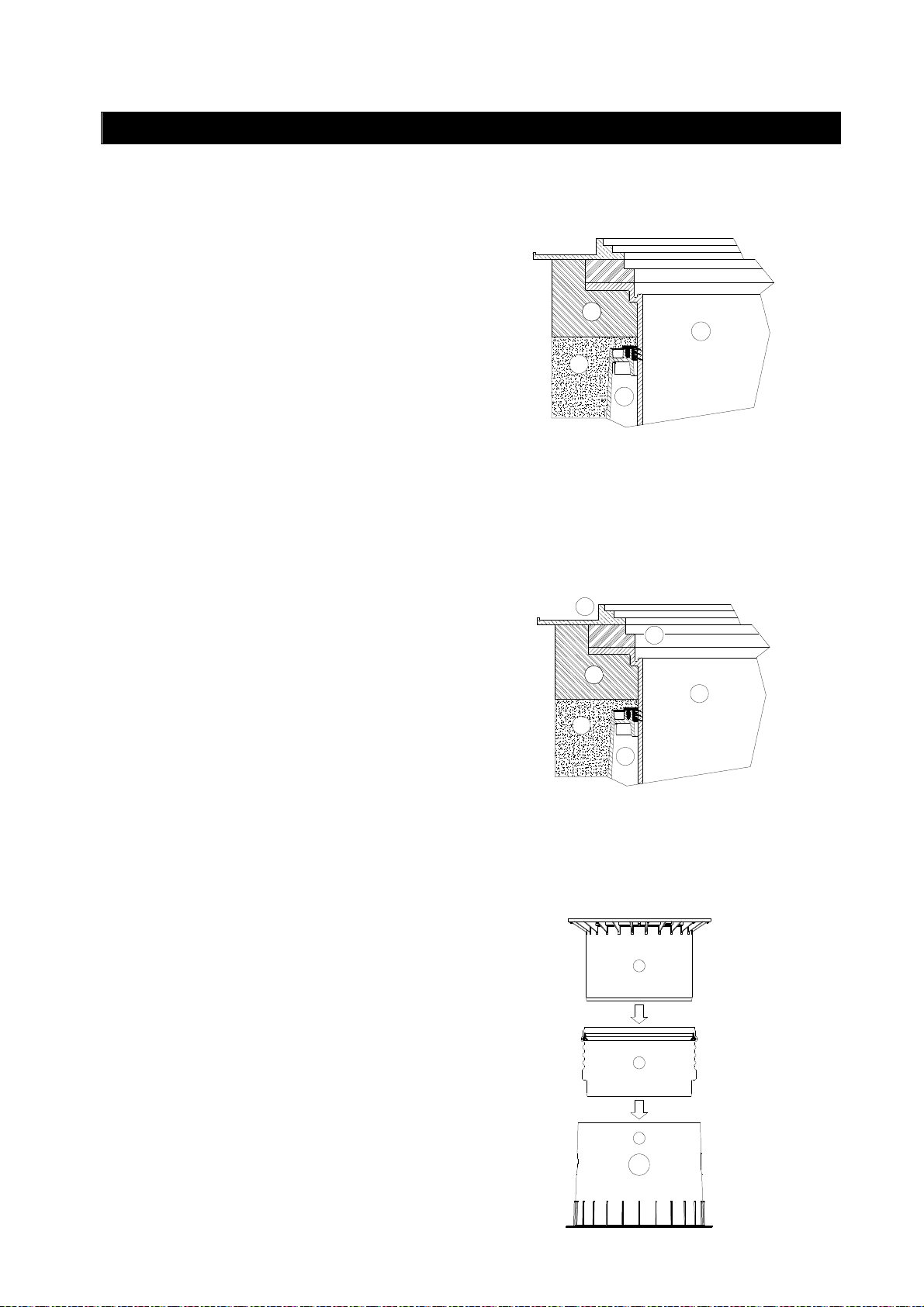
6.4 Teleskop-Domschacht PKW-befahrbar
Wird der Behälter unter PKW-befahrenen Flächen
installiert, muss das Teleskop im Kragenbereich
mit Beton (Belastungsklasse B25 = 250 Kg/m²)
unterfüttert werden. Die anzufüllende Betonschicht
muss umlaufend mind. 400 mm breit und ca.
200 mm hoch sein. Die Mindestüberdeckung über
der Tankschulter beträgt mind. 800 mm (max.
1050 mm mit Teleskop, Überdeckung bis max.
1500 mm mit Zwischenstück möglich).
Bitte beachten Sie, dass die entsprechende Behälterabdeckung bauseits gestellt werden muss.
Die Abdeckung muss mit Hydranten Schlüsseln A
oder B nach DIN 3223 geöffnet werden können
und für die vor Ort vorhandene Belastung geeignet
sein.
6.5 Teleskop-Domschacht LKW-befahrbar
4
1
2
3
Bei Installation unter LKW-befahrenen Flächen
wird das Teleskop wie in Punkt 6.4 unterfüttert.
Anschließend werden die Betonringe
(Ø 600 mm) und ein Gussrahmen mit sternförmiger Lastverteilung zur Aufnahme des Gussdeckels installiert. Der Gussrahmen muss eine Auflagefläche von ca. 1 m² haben. Die Mindestüberdeckung über der Tankschulter beträgt mind.
1000 mm (max. 1050 mm mit Teleskop, Überdeckung bis max. 1500 mm mit Zwischenstück möglich).
Bitte beachten Sie, dass die entsprechende Behälterabdeckung bauseits gestellt werden muss.
Die Abdeckung muss mit Hydranten Schlüsseln A
oder B nach DIN 3223 geöffnet werden können
und für die vor Ort vorhandene Belastung geeignet
sein.
6.6 Montage Zwischenstück
Wird bei größeren Erdüberdeckungen ein Zwischenstück benötigt, wird dieses unter Zuhilfenahme von Schmierseife in den Tankdom eingesetzt. In die oberste Nut des Zwischenstücks wird
die Profildichtung eingelegt und großzügig eingefettet. Anschließend den Teleskop-Domschacht
einschieben und an die geplante Geländeoberfläche anpassen.
Achtung: max. Erdüberdeckung 1500 mm
5
6
4
1
2
3
1
2
Teleskop-Domschacht (um 5° neigbar)
Zwischenstück (nicht kürzbar)
Tankdom (um 360° drehbar)
3
12 / 56
Page 14
mail@graf.info
www.graf.info
7. Löschwasser Ausbaukomponenten
7.1 Saugarmatur
Das Saugrohr hat einen Innendurchmesser von 125 mm und wird standardmäßig mit dem, sich im Lieferumfang enthaltenen, Löschwasser-Sauganschluss nach DIN 14244 mit A-Festkupplung verschraubt. Zur
Flanschabdichtung bitte beiliegende Dichtscheibe mit Stahleinlage verwenden!
Die Dichtflächen sind sauber, trocken und parallel ausgerichtet vorzubereiten und die Flanschverbindungen im Anschluss mit den jeweiligen Schraubensätzen, in mehreren Durchgängen gleichmäßig über
Kreuz mit einem max. Drehmoment in Höhe von 85 Nm, anzuziehen.
Der Löschwasser-Sauganschluss ist nach DIN 14244 einzubauen und vor Ort entsprechend zu überprüfen.
Je nach Einbau bzw. endgültiger Fertighöhe des Löschwasser-Sauganschlusses, muss das mitgelieferte
Saugrohr-Zwischenstück individuell angepasst bzw. separat, in gewünschter Sonderlänge, bestellt werden.
Es muss sichergestellt werden, dass der Löschwasservorrat sowie die entsprechenden Saugarmaturen
jederzeit frost- bzw. eisfrei sind.
Die Anzahl der Saugrohre richtet sich laut DIN 14230 nach dem jeweiligen Fassungsvermögen des
Löschwasserbehälters: bis 150 m³ min. 1 St./ >150<300 m³ min. 2 St./ über 300 m³ min. 3 St.
7.2 Entlüftung
Für jedes Saugrohr muss ein Entlüftungsrohr mit einem Innendurchmesser von mindestens 100 mm vorhanden sein. Bei mehreren Löschwasserbehältern ist für jeden Behälter mindestens ein Lüftungsrohr
vorzusehen. Das Entlüftungsrohr muss gegen Verschmutzen und Verstopfen geschützt sein.
Es muss sichergestellt werden, dass der Löschwasservorrat sowie die entsprechenden Entlüftungsarmaturen jederzeit frost- bzw. eisfrei sind.
7.3 Beschilderung
Der Pfosten mit Halter für das Hinweisschild "Löschwasserentnahmestelle", zur direkten Befestigung am
Saugrohr, ist bereits im Lieferumfang enthalten. Das entsprechende Hinweisschild nach DIN 4066-B2 mit
der jeweiligen Löschwasser-Inhaltsangabe ist bauseits zu stellen und dauerhaft und gut sichtbar am Halter zu befestigen.
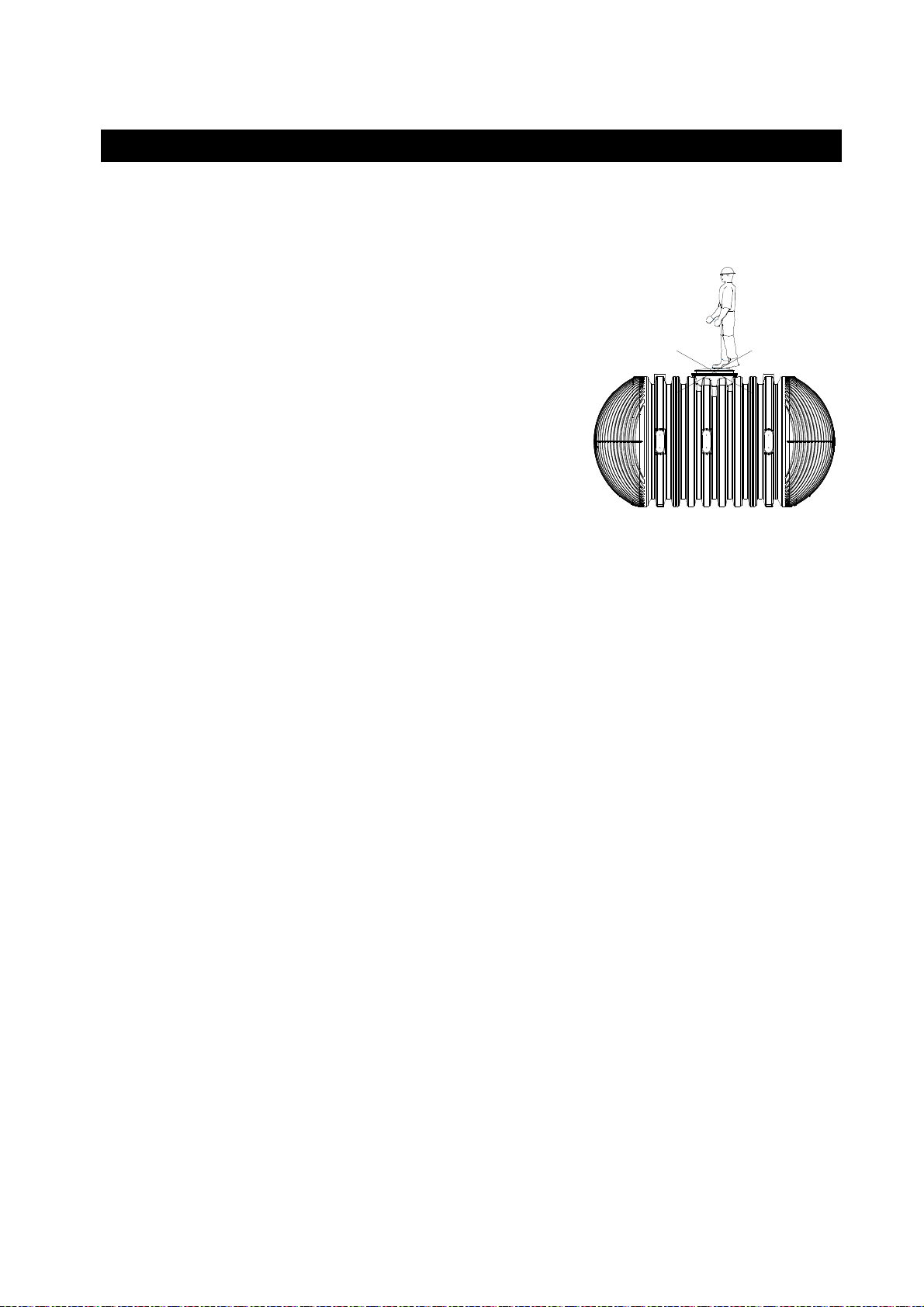
7.4 Einstiegsleiter
Um eine sichere Besteigbarkeit bis zum Behälterboden, sowie die Rettung aus dem Behälter
gewährleisten zu können, muss die mitgelieferte
Einstiegsleiter, wie in der aufgeführten Zeichnung,
mit dem dazugehörigen Befestigungsset fest im
A
Tankdom installiert werden. Ein Rückenschutz ist
nicht zulässig.
A
13 / 56
Page 15

8. Inspektion und Wartung
Die Gesamte Anlage ist mindestens alle drei Monate auf Dichtheit, Sauberkeit und Standsicherheit zu
überprüfen. Eine Wartung der gesamten Anlage sollte in Abständen von ca. 5 Jahren erfolgen.
Dabei sind alle Anlagenteile zu reinigen und auf ihre Funktion zu überprüfen, sodass eine einwandfreie
Löschwasserentnahme jederzeit gewährleitet ist.
Bei Wartungen sollte wie folgt vorgegangen werden:
• Flächen und Einbauteile mit Wasser reinigen
• Schmutz aus dem Behälter restlos entfernen
• Funktionsprüfung der Löschwasser-Ausbaukomponenten
Landesrechtliche Bestimmungen sind zu beachten.
www.graf.info
14 / 56
2018-07
Page 16
mail@graf.info
useful volume
www.graf.info
Installation / assembly / and maintenance instructions for
GRAF Carat XXL extinguishing water tanks
16 000* - 122 000* litres
Order no.: 380050 - 380071
*Please note that the
may be up to 10 %
below the total tank volume.
The points described in these instructions must be observed in all
cases. Failure to do so shall invalidate the warranty. For any additional items purchased through
GRAF, you will receive separate
installation instructions in the
transport packaging.
The tanks and the extinguishing
water removal components must
be checked for any
damage before the system is
transferred to the trench.
You can download any missing
instructions from www.graf.info or
request them from GRAF directly.
Contents
1. GENERAL INFORMATION
1.1 Safety
1.2 Labelling requirement
1.3 Acceptance
2. INSTALLATION CONDITIONS
3. TECHNICAL DATA
4. STRUCTURE OF TANK
5. INSTALLATION
5.1 Installation site
5.2 Covering heights
5.3 Foundation
5.4 Trench
5.5 Insertion and filling
5.6 Laying connections
6. FITTING TANK DOME AND TELESCOPIC DOME
SHAFT
6.1 Fitting tank dome
6.2 Fitting the telescopic dome shaft
6.3 Telescopic dome shaft for pedestrian loading
6.4 Telescopic dome shaft suitable for vehicle loading
6.5 Telescopic dome shaft lorry-bearing
6.6 Assembly of extension sleeve
7. EXTINGUISHING WATER REMOVAL COMPONENTS
7.1 Intake device
7.2 Ventilation
7.3 Signage
7.4 Access ladder
8. INSPECTION AND MAINTENANCE
16
16
16
16
17
18
21
21
22
22
22
22
24
24
25
25
25
25
26
26
26
27
27
27
27
27
28
15 / 56
Page 17
mail@graf.info
www.graf.info
1. General information
1.1 Safety
All work should be undertaken in compliance with the relevant accident prevention regulations according
to BGV C22. A second person is required for safety reasons, particularly when inspecting tanks.
In addition, the applicable regulations and standards must be respected during installation, assembly, maintenance, repairs etc.
Relevant information can be found in the corresponding sections of
these instructions.
The entire system must always be switched off and secured
against unauthorised resetting during any work on the system or
system components.
The tank cover must always be kept closed, except during work
inside the tank, otherwise the risk of accidents is high. The rain
guard cover fitted upon delivery is only transport packaging, it is not
suitable for pedestrian loading and is not childproof. After delivery,
it must be immediately replaced with a suitable cover provided by
the customer.
GRAF provides an extensive range of accessories, which are all
coordinated and can be combined to form complete systems. The use of accessories that have not been
approved by GRAF results in the exclusion of the warranty/guarantee.
1.2 Labelling requirement
The post with holder for sign "Extinguishing Water Extraction Point", for securing directly to the intake
pipe, is included in the scope of delivery. The corresponding sign in accordance with DIN 4066-B2 with
the relevant extinguishing water volume details should be provided by the customer and secured to the
holder permanently and in a highly visible place.
1.3 Acceptance
Every new extinguishing water tank should be accepted by an officer from the relevant authority and is to
be checked for its function. The fire protection specialist responsible verifies and calculates the amount of
extinguishing water needed. Please note that the actual useful volume of extinguishing water may be up
to 10 % below the stated total tank volume.
16 / 56
Page 18

mail@graf.info
2. Installation conditions
Covering heights with telescopic lorry dome
shaft (cover in accordance with DIN 3223 - to be
provided by the customer) in landscaped areas
suitable for pedestrian loading 750-1050 mm.
Maximum covering height with extension sleeve
and telescopic lorry dome shaft (cover in accordance with DIN 3223 - to be provided by the
customer).
Maximum covering height 1500 mm.
www.graf.info
Teleskop-Domschacht LKW
(Abdeckung nach DIN 3223 -
bauseits zu stellen)
750 - 1050
max. 1500
Covering heights with telescopic lorry dome
shaft (cover in accordance with DIN 3223 – to
be provided by the customer) in area driven over
by vehicles >800<1500 mm.
Covering heights with telescopic lorry dome
shaft (cover in accordance with DIN 3223 – to
be provided by the customer) in area driven over
by lorries >1000<1500 mm.
(Load up to max. 40 t)
The tanks may only be installed in ground water
with some limitations. If you can expect the
ground water to be higher than shown in this
figure, even if only occasionally, it should be
discharged through drainage.
Max.
> 800 < 1500
max. 40 to
max. 8 to
> 1000 < 1500
> 800 < 1500
Max.
Covering heights with ground water >800<1500
mm.
17 / 56
Page 19

mail@graf.info
Total
Tank
Tank
Tank
Tank
Tank
www.graf.info
3. Technical data
Min. 140
Htot
Tank
(litres)
Item no.
Max. 440
220
4 4
3 3 3
330
5
L
220
250
2
Htot
1
B
220
495
610
H
16 000 26 000 36 000 46 000 56 000 66 000 76 000 86 000 96 000 106 000 116 000
380050 380052 380054 380056 380058 380060 380062 380064 380066 380068 380070
Weight
(kg)
L (mm)
B (mm)
Technical data
H (mm)
height
(Htot)
(mm)
bases
(bottom)
DN100
bases
(top)
DN150
cylinder
(sides)
DN100
Connection surfaces
cylinder
(top)
DN200
dome
DN150
805 1150 1495 1840 2185 2530 2875 3220 3565 3910 4255
4660 7045 9430 11815 14200 16585 18970 21355 23740 26125 28510
2500
2550
3160
2
2
12 16 20 24 28 32 36 40 44 48 52
2 3 4 5 6 7 8 9 10 11 12
5
18 / 56
Page 20

mail@graf.info
Total
Tank
Tank
Tank
Tank
Tank
www.graf.info
3. Technical data
340 (Mini)
Htot
Tank
(litres)
Item no.
220
4
3 3
440 (Maxi)
330
5
L
5
3 3
610
4
Htot
140
Htot
220
220
495
610
2
H
1
B
22 000 32 000 42 000 52 000 62 000 72 000 82 000 92 000 102 000 112 000 122 000
380051 380053 380055 380057 380059 380061 380063 380065 380067 380069 380071
Weight (kg)
L (mm)
B (mm)
Technical data
H (mm)
height
(Htot)
(mm)
bases (bottom)
DN100
bases
(top)
DN150
cylinder
(sides)
DN100
Connection surfaces
cylinder
(top)
DN200
dome
DN150
1015 1360 1705 2050 2395 2740 3085 3430 3775 4120 4465
6145 8530 10915 13300 15685 18070 20455 22840 25225 27610 29995
2500
2550
3160
2
2
16 20 24 28 32 36 40 44 48 52 56
2 3 4 5 6 7 8 9 10 11 12
10
19 / 56
Page 21

mail@graf.info
www.graf.info
3. Technical data
C
m³
F
E
Extinguishing
water removal
components
Description
Material
Technical data
Weight (kg)
Diameter
(mm)
B
A
D
A B C D E F
intake pipe
Suction connection
with A fixed coupling
Extension piece for
strainer
anti-vortex plate and
Intake pipe including
and sieve
Vent pipe with hood
sign
Access ladder
Post with holder for
V2A V2A PE/ V2A V2A V2A Alu
11.5 13.5 13 5.5 5 5
DN 125 DN 125 DN 125 DN 100 - -
L (mm)
W (mm)
H (mm)
- - - -
- - - -
550 1200 2400 1000 2000 2900
20 / 56
Post: 40
Holder: 250
Post: 40
Holder: 200
-
355
Page 22

mail@graf.info
www.graf.info
4. Structure of tank
Telescopic lorry dome shaft (cover in
accordance with DIN 3223 - to be pro-
vided by the customer)
Profile seal of tank dome / telescope
Tank dome (can be rotated 360°)
Profile seal of tank / tank dome
Carat XXL extinguishing water tank
Suction connection with A fixed coupling
in accordance with DIN 14244
Extension piece for intake pipe with DN
125 flange
Intake pipe with DN 125 flange including
anti-vortex plate and strainer
DN 100 vent pipe with hood and sieve
³
9
10
5
1
2
3
4
11
6
7
8
Post with holder for customer sign "Extinguishing
Water Extraction Point" in accordance with DIN
4066-B2
Access ladder including mounting kit for mounting
11
in tank dome
In ground
Telescopic lorry dome shaft (cover in
accordance with DIN 3223 - to be pro-
vided by the customer)
Compacted base layer
Surround
(round gravel, max. grain 8/ 16)
Covering layer
ß nach DIN 4124
1 4
5. Installation
Carat XXL extinguishing water tank
Concrete layer for surfaces driven on by cars/lorries
Suction connection with A fixed coupling in accord-
ance with DIN 14244
Vent pipe with hood and sieve
Post with holder for customer sign in accordance
with DIN 4066-B2
8
2
7
m³
109
5
ß
> 100 mm
< 300 mm
< 300 mm
< 300 mm
< 300 mm
< 300 mm
< 300 mm
< 300 mm
> 150 mm
6
21 / 56
3
Page 23

mail@graf.info
www.graf.info
5. InstallationInstallation
5.1 Installation site
The extinguishing water extraction point must be outside the debris zone of buildings. Access for the fire
brigade should be provided to the extraction point from the public road. The access route must meet the
requirements of DIN 12090 provided these don't contradict local requirements. Exceptions require the
agreement of the body responsible for fire protection.
5.2 Covering heights
Please note that the telescopic lorry dome shaft contained in the standardised scope of supply (cover in
accordance with DIN 3223 - to be provided by the customer) refers to a general coverage height of
750-1050 mm. If a different level of soil cover is needed, corresponding extension sleeve pieces must be
ordered to extend it (note: max. soil cover 1500 mm).
Depending on installation and/or final finished height of the extinguishing water suction connection, the
intake pipe extension sleeve supplied has to be adapted individually and/or ordered separately in the
desired special length. When positioning, please note DIN 14244.
5.3 Foundation
The following criteria must be verified prior to installation:
• The structural suitability of the soil in accordance with DIN 18196
• Maximum groundwater levels/ drainage of the subsoil
• Types of loading present, e. g. traffic load
A soil survey should be requested from the local building authority to determine the physical properties of
the soil.
5.4 Trench
To ensure that sufficient working space is available, the base area of the trench must exceed the tank
dimensions by 500 mm on all sides. The distance from fixed structures must be at least 1000 mm.
The embankment should be built in accordance with DIN 4124. The foundation must be horizontal and
even and must offer sufficient load-bearing capacity.
The trench must be deep enough that the maximum earth cover above the tank (see 2 - Installation conditions) is not exceeded. For the system to be usable all year round, the tank and water-carrying parts
must be installed in a frost-free zone. The frost-free depth is usually around 600-800 mm; for accurate
information, please contact the responsible authority.
The substructure is made from a layer of compacted round gravel (grain 8/ 16, approx. 150-200 mm
thick).
22 / 56
Page 24

mail@graf.info
tank dimensions by at least
www.graf.info
5. Installation
5.4.1 Positioning on a slope, embankment etc.
If the tank is installed in immediate proximity (less
than 5 m) to a slope, mound or embankment, a
statically calculated supporting wall must be constructed to bear the pressure of the soil. The wall
must exceed the
500 mm in all directions and must be at least
1000 mm away from the tank.
5.4.2 Groundwater and cohesive (non-water-permeable)
Sufficient drainage of the groundwater / seeping
water should be ensured if groundwater occurs
occasionally and if the soils are cohesive and
water-impermeable (e. g. clay) so that the tanks
never stand in more groundwater than is stated in
the table. If necessary, the drainage pipe must
end in a vertical DN 300 pipe in which a submersible pressure pump is fitted to pump out the excess water. The pump should be checked regularly. If the tanks are expected to be immersed
deeper, sufficient drainage should always be
ensured.
Covering heights with ground water
>800<1500 mm.
We generally recommend laying a drainage pipe
because the ground water level may rise unexpectedly during long periods of rain.
Submersion depth
5.4.3 Installation next to driven-on surfaces
If the underground tanks are installed next to
roadways used by heavy vehicles of more than
40 t, the minimum distance from these surfaces
must be at least the depth of the trench.
soils (e.g. clay)
> 800 < 1500
Max. Max.
Tank size
> H
all tank sizes
1275 mm
5.4.4 Connecting multiple tanks
Two or more tanks are connected via welded DN
250 pipe connections (twice the nominal diameter
of the intake pipe). The pipe connections should
be positioned as far down the tank as possible.
Ensure that the distance between the underground tanks is at least 600 mm.
H
> 600
23 / 56
Page 25

mail@graf.info
www.graf.info
5. Installation
5.5 Insertion and filling
The tanks should be brought into the prepared
trench with a suitable device without any jolts.
Before the surround is filled the tank is filled with
around 25 cm water, the surround (round gravel,
max. grain 8/ 16mm) is then added in layers,
max. 40 cm at a time, up to the top edge of the
tank and compressed. The individual layers must
be well compressed with a hand tamper. Be careful to avoid damaging the tank when compressing
the gravel. Mechanical compression machines
must never be used. The surround must be at
least 500 mm wide.
5.6 Laying connections
astewater must not enter the extinguishing
W
water tanks.
40 cm
25 cm
When filling, the water between the outlet of the
filling pipe and the maximum tank water level in
accordance with DIN 1988-6 must come into
contact with the free atmosphere. An air cushion
of at least 100 mm must be observed between
the maximum water level and tank cover. If necessary, the tank should be protected against
overfilling.
All inlet and overflow pipes must be laid with an
incline of at least 1 % in the direction of flow
(remember that subsequent settling may occur).
If the tank overflow is connected to a public sewage network, in accordance with DIN 1986, this
Kanal
>1%
must be protected from backflow. All control lines
must be routed in an empty pipe, which must be
laid at an angle to the tank, as straight as possible without any sagging. Any bends needed
should be produced using a 30° adapter.
Important: The empty pipe should be connected to an opening above the max. water level.
>1%
>1%
24 / 56
Page 26

mail@graf.info
www.graf.info
6. Fitting tank dome and telescopic dome shaft
6.1 Fitting tank dome
Before actually fitting, the seal provided between
the tank and tank dome is slid onto the support
profile of tank neck "B". The tank dome is then
aligned to the pipes and slid into the tank neck up
to the stop. It is essential that the upper seal "A"
(already pre-mounted) is correctly positioned.
"A" "B"
6.2 Fitting the telescopic dome shaft
The supplied telescopic lorry dome shaft (cover in
accordance with DIN 3223 - to be provided by the
customer) allows the shaft to be smoothly adjusted
to the terrain surface. To assemble, the profile seal
(material EPDM) of the tank dome is rubbed in
with plenty of soft soap (do not use lubricants with
a mineral oil base because they will corrode the
seal). The telescopic dome shaft is then greased,
slid in and aligned to the terrain surface.
"A"
"B"
6.3 Telescopic dome shaft for pedestrian loading
mportant: To prevent loads from being transferred
I
to the tank, the telescope is filled in layers with
round gravel (max. grain 8/ 16) and evenly
compressed. Avoid damaging the tank dome and
telescope. The minimum covering above the
tank shoulder is at least 750 mm (max. 1050 mm
with telescope, coverage up to max. 1500 mm
possible with extension sleeve).
Please note that the corresponding tank cover has
to be provided by the customer.
It must be possible for the cover to be opened with
hydrant keys A or B in accordance with DIN 3223
and the cover must be appropriate for the loading
on site.
2
1
3
25 / 56
Page 27

mail@graf.info
www.graf.info
6. Fitting tank dome and telescopic dome shaft
6.4 Telescopic dome shaft suitable for vehicle loading
If the tank is installed below a surface driven on by
vehicles, the telescope must be lined with concrete in the collar area (load class B25 = 250 kg/
m²). The concrete layer must be at least 400 mm
wide and approx. 200 mm high all the way round.
The minimum covering above the tank shoulder is
at least 800 mm (max. 1050 mm with telescope,
coverage up to max. 1500 mm possible with extension sleeve).
Please note that the corresponding tank cover has
to be provided by the customer.
It must be possible for the cover to be opened with
hydrant keys A or B in accordance with DIN 3223
and the cover must be appropriate for the loading
on site.
6.5 Telescopic dome shaft lorry-bearing
4
1
2
3
When installing below surfaces driven on by lorries, the telescope is lined as described in 6.4.
The concrete rings (diameter 600 mm) and a
cast frame with star-shaped load distribution are
then installed to support the cast cover. The cast
frame must have a contact area of approx. 1 m².
The minimum covering above the tank shoulder is
at least 1000 mm (max. 1050 mm with telescope,
coverage up to max. 1500 mm possible with extension sleeve).
Please note that the corresponding tank cover has
to be provided by the customer.
It must be possible for the cover to be opened with
hydrant keys A or B in accordance with DIN 3223
and the cover must be appropriate for the loading
on site.
6.6 Assembly of extension sleeve
If an extension sleeve is needed for larger earth
covers it is inserted into the tank dome with the aid
of soft soap. The profile seal is fitted in the topmost
groove of the extension sleeve and greased with
plenty of lubricant. Then slide the telescopic dome
shaft into place and adjust to suit the planned terrain surface.
5
6
4
1
2
3
1
Please note: max. soil cover 1500 mm
Telescopic dome shaft (tilts by 5°)
Extension sleeve (cannot be shortened)
Tank dome (can be rotated 360°)
2
3
26 / 56
Page 28

mail@graf.info
www.graf.info
7. Extinguishing water removal components
7.1 Intake device
The intake pipe has an inner diameter of 125 mm and as standard is screwed down to the extinguishing
water suction connection provided in the scope of supply in accordance with DIN 14244 by means of an A
fixed coupling. Please use the washer provided with a steel insert to seal the flange!
The sealing surfaces must be clean, dry and parallel, and the flanged connections must then be tightened
evenly and crosswise with a maximum torque of 85 Nm in several passes using the respective screw sets.
The extinguishing water suction connection should be built in accordance with DIN 14244 and is to be
checked on site.
Depending on installation and/or final finished height of the extinguishing water suction connection, the
intake pipe-extension sleeve supplied has to be adapted individually and/or ordered separately in the
desired special length.
You must ensure that the extinguishing water supply and corresponding intake devices are free from frost
and ice at all times.
In accordance with DIN 14230, the number of intake pipes depends on the capacity of the extinguishing
water tank: up to 150 m³ min. 1 pipe/ >150<300 m³ min. 2 pipes/ above 300 m³ min. 3 pipes.
7.2 Ventilation
There must be one vent pipe with an inner diameter of at least 100 mm for every intake pipe. If using
several extinguishing water tanks, there must be at least one vent pipe for each tank. The vent pipe must
be protected from contamination and blockages.
You must ensure that the extinguishing water supply and corresponding vent devices are free from frost
and ice at all times.
7.3 Signage
The post with holder for sign "Extinguishing Water Extraction Point", for securing directly to the intake
pipe, is included in the scope of delivery. The corresponding sign in accordance with DIN 4066-B2 with
the relevant extinguishing water volume details should be provided by the customer and secured to the
holder permanently and in a highly visible place.
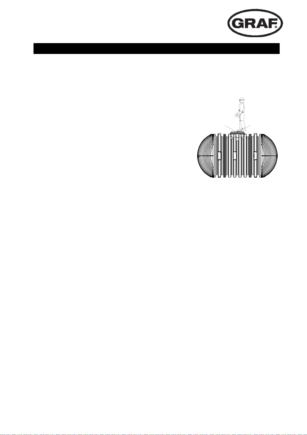
7.4 Access ladder
In order to ensure a safe way of accessing the tank
base and rescuing people from inside the tank, the
access ladder provided must be permanently installed in the tank dome with the associated mount-
A
ing kit as shown in the drawing. Back protection is
not permitted.
A
27 / 56
Page 29

mail@graf.info
www.graf.info
8. Inspection and maintenance
The entire system must be checked for tightness, cleanliness and stability at least once every three
months. The entire system should be maintained approximately every 5 years.
This involves cleaning all system parts and checking that they are functioning correctly so that extinguishing water can be easily extracted at all times.
For maintenance, proceed as follows:
• Clean surfaces and built-in parts with water
• Remove all dirt and contamination from the tank
• Functional check of the extinguishing water removal components
Please note the national requirements.
www.graf.info
28 / 56
2018-07
Page 30

Notice d’installation et d‘entretien
Carat XXL GRAF Réserve Incendie
16.000* à 102.000* Litres
Ref: 380050 à 380067
mail@graf.info
www.graf.info
Afin de garantir le bon fonctionnement et la longévité de votre
installation, les différents points
décrits dans cette notice doivent
scrupuleusement être respectés. Tout manquement à ces
règles annulera systématiquement la garantie. Lisez également toutes les notices des
autres éléments fournis par la
société GRAF. Vous trouverez
les notices de montage jointes
dans l’emballage.
Avant de positionner la cuve
dans la fouille, il est important
de vérifier que la cuve et les
équipement incendie n’ont pas
été endommagés.
L’installation doit être réalisée
par un installateur professionnel.
SOMMAIRE
1. GENERALITES
1.1 Sécurité
1.2 Obligation de marquage
1.3 Identification
2. CONDITION D‘INSTALLATION
3. CARACTERISTIQUE TECHNIQUE
4. ASSEMBLAGE DU RESERVOIR
5. MISE EN PLACE ET MONTAGE
5.1 Emplacement
5.2 Hauteur de remblai
5.3 Terrain
5.4 Fouille
5.5 Mise en place et remplissage
5.6 Raccordement
6. MONTAGE DU DOME ET DE LA REHAUSSE
TELESCOPIQUE
6.1 Montage du dôme
6.2 Montage de la rehausse télescopique
6.3 Rehausse telescopique passage camions
6.4 Montage de la rallonge
7. EQUIPEMENT INCENDIE
7.1 Raccordement d’aspiration
7.2 Aération
7.3 Signalisation
7.4 Echelle d‘inspection
8. INSPECTION ET ENTRETIEN
30
30
30
30
31
32
35
35
36
36
36
36
38
38
39
39
39
40
40
41
41
41
41
41
42
29 / 56
Page 31
1.1 Sécurité
mail@graf.info
www.graf.info
1. GENERALITES
Les règles de sécurité doivent impérativement être respectées lors de l’installation de la cuve. Durant
l’inspection de la cuve, une 2
ème
personne doit être présente. Les instructions d’installation, de montage,
d’entretien et de réparation indiquées ci-après doivent être scrupuleusement respectées.
Durant toute intervention sur la cuve ou les accessoires,
l’installation complète doit être mise hors service.
Pour des raisons de sécurité, le couvercle de la cuve doit impérativement être verrouillé.
Le couvercle de protection provisoire placé sur la cuve lors de la
livraison doit immédiatement être remplacé par la rehausse télescopique avec le couvercle définitif en fonction du besoin.
La société GRAF vous propose une large gamme d’accessoires
d’une grande compatibilité. GRAF décline toute prise en charge
sous garantie en cas d’utilisation d’accessoires non conformes.
1.2 Obligation de marquage
La plaque signalétique fourni portant l’inscription « RESERVE INCENDIE » doit être installée à proximité
directe de la colonne d’aspiration
1.3 Identification
Chaque installation d’une réserve incendie doit être identifiée et contrôlée par les autorités publiques
compétentes. Le certificat de conformité et la quantité nécessaire d’eau, sera fourni par les autorités pour
la protection incendie.
Le volume utile de la réserve incendie peut varier de moins 10% par rapport au volume total du réservoir.
.
30 / 56
Page 32

2. CONDITION D‘INSTALLATION
Hauteurs de recouvrement avec dôme et rehausse télescopique est comprise entre 750mm
– 1050mm pour un passage piétons
Hauteur de recouvrement maximale avec dôme
+ rallonge et rehausse télescopique est égale à
1500mm.
mail@graf.info
www.graf.info
750 - 1050
max. 1500
Hauteurs de recouvrement avec rehausse télescopique en fonte (avec couvercle en fonte et
anneau béton de classe B – non fournis) est de
>800<1500mm dans une zone soumise aux
charges de voitures (charge max. 3,5 t).
Hauteurs de recouvrement avec rehausse télescopique passage camion >1000<1500mm (avec
anneau et couvercle en fonte de classe D – non
fourni, charge max. 40 t).
Hauteurs de recouvrement dans le cas d’une
installation dans la nappe phréatique jusqu’à
l’équateur de la cuve (partie hachurée) sont
comprises entre 800 et 1500mm.
En cas de remontée de nappe, si la hauteur
indiquée est dépassée, il est impératif de mettre
en place un système de drainage (puit avec
pompe) pour limiter la montée du niveau de
l’eau.
Max.
> 800 < 1500
max. 40 to
max. 8 to
> 1000 < 1500
> 800 < 1500
Max.
31 / 56
Page 33

mail@graf.info
Dôme du r
é-
www.graf.info
3. CARACTERISTIQUE TECHNIQUE
Min. 140
Htot
Réservoirs
(Litres)
Ref.
Max. 440
245
4 4
3 3 3
355
5
L
250
Htot
245 245
2
1
B
520
610
H
16.000 26.000 36.000 46.000 56.000 66.000 76.000 86.000 96.000
380050 380052 380054 380056 380058 380060 380062 380064 380066
Poids (kg)
L (mm)
l (mm)
Données Techniques
H (mm)
Htot (mm)*
Côté de cuve
(en bas) DN110
Côté de cuve
(en haut) DN160
Corps de cuve
(côtés) DN110
Corps de cuve
(en haut) DN200
servoir
Surface de raccordements
DN110
805 1150 1495 1840 2185 2530 2875 3220 3565
4660 7045 9430 11815 14200 16585 18970 21355 23740
2500
2550
3160
2
2
12 16 20 24 28 32 36 40 44
2 3 4 5 6 7 8 9 10
5
32 / 56
Page 34

mail@graf.info
Côté
Côté cuve
Corps de
Corps de
Dôme du
www.graf.info
3. CARACTERISTIQUE TECHNIQUE
Min. 140
Htot
Réservoirs
(Litre)
Ref.
Poids (kg)
Max. 440
245
4 4
3 3
5
L
5
3 3
355
250
Htot
245 245
2
1
B
520
610
H
22.000 32.000 42.000 52.000 62.000 72.000 82.000 92.000 102.000
380051 380053 380055 380057 380059 380061 380063 380065 380067
1015 1360 1705 2050 2395 2740 3085 3430 3775
L (mm)
l (mm)
Données techniques
H (mm)
Htot (mm)*
cuve(en bas)
DN110
(en haut)
DN160
cuve (côté)
DN110
cuve (en haut)
DN200
Surfaces de raccordement
réservoir
DN110
6145 8530 10915 13300 15685 18070 20455 22840 25225
2500
2550
3160
2
2
16 20 24 28 32 36 40 44 48
2 3 4 5 6 7 8 9 10
10
33 / 56
Page 35

mail@graf.info
www.graf.info
3. CARACTERISTIQUE TECHNIQUE
C
m³
F
E
Accessoires
Réserve
Incendie
Designation
Matières
Poids (kg)
Données techniques
B
A
D
A B C D E F
(hydrant)
bride d‘accouplement
Raccord pompier avec
d’aspiration
Rallonge pour colonne
anti-tourbillon
Colonne d’aspiration
avec crépine et plateau
Event
Plaque signalétique
Echelle d‘inspection
V2A V2A PE/ V2A V2A V2A Alu
11,5 13,5 13 5,5 5 5
Ø (mm)
L (mm)
l (mm)
H (mm)
DN 100 DN 125 DN 125 DN 100 - -
- - - -
- - - -
Support: 40
Plaque: 250
Support: 40
Plaque: 200
355
550 1200 2400 1000 2000 2900
34 / 56
-
Page 36

mail@graf.info
deur
selon les règles de l’art
www.graf.info
4. ASSEMBLAGE DU RESERVOIR
Rehausse télescopique passage camoins (anneau et couvercle – non four-
nis)
Joint à lèvres EDPM
Dôme (pivotant à 360°)
Joint à lèvres EDPM
Réserve Incendie Carat XXL
Raccord pompier DN100 avec bride
d‘accouplement
Rallonge pour colonne d‘aspiration DN
125
Colonne d‘aspiration DN 125 avec cré-
pine et plateau anti tourbillon
Event DN 100
³
9
10
5
Plaque signalétique
11
Echelle d‘inspection
6
1
2
7
3
4
8
11
5. MISE EN PLACE ET MONTAGE
Terrain
Rehausse télescopique (avec couvercle
et anneau – non fournis)
Lit de pose en gravier compacte
Remblai (gravier rond granulométrie
8/16 ou approchant)
Couche de recouvrement
ß : Angle en fonction de la profon-
ß nach DIN 4124
1 4
Réserve Incendie Carat XXL
Dalle de répartition béton pour surfaces soumises
à un passage véhicules/camions
Raccord pompier DN100 avec bride d‘accouplement
Event
Plaque signalétique
8
2
7
m³
109
5
ß
> 100 mm
< 300 mm
< 300 mm
< 300 mm
< 300 mm
< 300 mm
< 300 mm
< 300 mm
> 150 mm
6
35 / 56
3
Page 37

mail@graf.info
www.graf.info
5. MISE EN PLACE ET MONTAGE
5.1 Emplacement
L’emplacement du réservoir incendie doit répondre aux directives des autorités. L’accès et le passage
doivent être accessibles aux engins de lutte contre l’incendie.
5.2 Hauteur de remblai
La hauteur de recouvrement avec rehausse télescopique passage camions est de 1000mm à 1500mm
max avec rallonges.
La hauteur de l’hydrant est fixe grâce à la rallonge fournie avec la colonne d’aspiration.
5.3 Terrain
Avant l’installation, les points suivants doivent être impérativement vérifiés :
• La nature du terrain
• La hauteur de la nappe phréatique et capacité de drainage du sol
• Les charges devant être supportées par la cuve (par exemple : passage camions)
Pour déterminer les conditions physiques du sol, il convient d’effectuer une étude de sols.
5.4 Fouille
La fouille doit avoir des dimensions suffisantes pour permettre une bonne mise en place de la cuve. Prévoir un minimum de 50 cm de chaque côté de la cuve et 1 m de toute construction.
Ne pas placer la cuve au pied d’une pente ou d’un talus. La pression exercée par la terre ou par les écoulements d’eau à cet endroit peuvent endommager la cuve. Le terrain doit être plan et homogène, et garantir une surface portante suffisante (voir chapitre 5.4.1).
La profondeur de la fosse doit être calculée de manière à ce que le recouvrement de la cuve corresponde
aux instructions du chapitre 2. Pour une utilisation de la cuve durant toute l’année, il est indispensable
d’enterrer la cuve ainsi que les accessoires en hors gel, soit à environ de 60 à 80 cm sous terre.
Mettre en place un lit de de gravier 8/16 ou approchant d’environ 20 cm.
36 / 56
Page 38

mail@graf.info
www.graf.info
5. MISE EN PLACE ET MONTAGE
5.4.1 Pentes, talus
Pour toute implantation de la cuve à proximité
d’une pente (< 5 m), d’un monticule de terre ou
d’un talus, il faut mettre en place un mur de soutènement issu d’un calcul de résistance statique
pour contenir la poussée du terrain. Le mur devra
être plus large d’au moins 500 mm de toutes les
directions de la cuve et avec un éloignement
minimal d’au moins 1000 mm.
5.4.2 Nappe phréatique et terrains argileux/difficiles
Dans le cas où la cuve est installée plus profondément dans la nappe phréatique qu’indiqué
dans le tableau ci-contre, dans un terrain argileux, ou un terrain non perméable (non drainant),
il est impératif d’évacuer les eaux par un drainage tout autour de la cuve. Si nécessaire relier
le tuyau de drainage à un tuyau vertical DN 300
équipé d’une pompe de relevage. Le bon fonctionnement de cette pompe doit être vérifié régulièrement. Le système d’évacuation doit être dimensionné de façon à empêcher la montée du
niveau d’eau.
> 800 < 1500
Max. Max.
Hauteur de recouvrement
>800<1500 mm.
D’une manière générale, nous recommandons la
V
olume du Réservoir
pose d’une conduite de drainage avec pompe de
relevage. En effet, en cas d’événements pluviométriques prolongés, une montée de la nappe
Profondeur d‘immersion
phréatique peut se produire.
5.4.3 Installation à proximité de surfaces roulantes (passage véhicules)
Si les cuves à enterrer sont installées à proximité
de surfaces roulantes où circulent des véhicules,
la distance minimale par rapport à ces surfaces
> H
doit correspondre au minimum à la profondeur de
la fouille (voir ci-contre).
5.4.4 Jumelage de plusieurs réservoirs
Le raccordement de deux ou plusieurs réservoirs
s’effectue par le bas en DN 250. Il faut veiller à
ce que la distance entre les réservoirs soit au
moins de 600mm.
TOUS
1275 mm
H
> 600
37 / 56
Page 39

mail@graf.info
www.graf.info
5. MISE EN PLACE ET MONTAGE
5.5 Mise en place et remplissage
Les cuves doivent être installées dans la fouille
avec un matériel adapté.
Pour éviter toute déformation de la cuve et assurer son maintien dans la fouille, remplir d’eau 25
cm de la cuve avant de remblayer progressivement par couches successives de 40 cm de gravier 8/16 ou approchant sur le pourtour de la
cuve, afin de bien remplir toutes les cavités.
Chaque couche doit être tassée manuellement et
non mécaniquement, jusqu’au recouvrement total
de la cuve. L’espace tout autour de la cuve doit
être au minimum de 50cm.
40 cm
25 cm
5.6 Raccordement
Ne pas déverser des eaux usées dans un Réservoir Incendie.
Lors du remplissage de la cuve, le fil d’eau de
ortie doit impérativement être inférieur au fil
s
d’eau d’entrée de la cuve. Respecter une distance de 100mm entre le haut de la cuve et le fil
d’eau de sortie.
Les tuyaux d’arrivée doivent être posés avec une
inclinaison d’au moins 1%. Le raccordement doit
se faire aux entrées prévues sur le dôme de la
cuve. Le tuyau d’évacuation peut-être muni d’un
clapet anti-retour (non fourni).La cuve doit être
installée au minimum à 1m de toutes fondations.
Kanal
>1%
>1%
>1%
38 / 56
Page 40

mail@graf.info
www.graf.info
6. MONTAGE DU DOME ET DE LA REHAUSSE TELESCOPIQUE
6.1 Montage du dôme
Placer le joint d’étanchéité livré avec le dôme dans
la rainure du trou d’homme de la cuve (B). Le
dôme est orientable selon les arrivées de tuyaux.
Veillez également au bon positionnement du joint
placé sur le dessus du dôme(A).
„A“ „B“
„A“
„B“
6
.2 Montage de la rehausse télescopique
La rehausse télescopique permet un ajustement
facile et précis de la cuve par rapport au niveau du
sol.
Montage : placer le joint d’étanchéité comme indiqué ci-dessus. Enduire généreusement les lèvres
du joint avec de la graisse blanche, ne pas utiliser
de graisse à base d’huile minérale, trop agressive
pour le joint. Enduire également de graisse
blanche la rehausse télescopique, glisser celle-ci
dans le dôme de la cuve et ajuster la hauteur au
niveau du sol.
39 / 56
Page 41

mail@graf.info
www.graf.info
6.3 Rehausse telescopique passage camions
Dans le cas d’un passage camions jusqu’à 40 T
au-dessus de la cuve Il est impératif d’installer
une dalle de répartition en béton maigre (classe
de charge D400). La dalle de répartition en béton
autour de la rehausse, doit faire au moins 400 mm
de large et 200 mm de hauteur. Ensuite, il faut
installer un anneau et un couvercle béton ou
en fonte (non fournis). Le recouvrement minimum (dôme inclus) de la cuve est > 800 mm (max.
1050 mm avec la rehausse maxi et jusqu’à 1500
mm au maximum avec 2 rallonges). L’anneau en
béton ou en fonte doit avoir une surface d’appui
d’environ 1 m².
Le couvercle doit pouvoir s’ouvrir avec une clé à
hydrant.
5
6
4
1
2
3
6.4 Montage de la rallonge
Pour un remblai plus conséquent, il est nécessaire
d’utiliser la rallonge muni d’un joint: enduire généreusement ce joint avec de la graisse blanche.
Enduire également de graisse blanche la rehausse télescopique, glisser celle-ci dans le dôme
de la cuve et ajuster la hauteur au niveau du sol.
Attention = remblai maxi de 1500 mm
(avec 2 rallonges)
Rehausse télescopique (inclinable à 5°)
Rallonge
Dôme de la cuve (pivotant à 360°)
1
2
3
40 / 56
Page 42

mail@graf.info
www.graf.info
7. EQUIPEMENT INCENDIE
7.1 Raccordement d’aspiration
La colonne d’aspiration est livrée en DN125 et se réduit en DN100 au niveau du raccord pompier(hydrant)
grâce à une bride d’accouplement . Utilisez les brides livrées pour assurer l’étanchéité.
Les surfaces d’étanchéité doivent être propres et sèches de part et d’autre des raccords, disposez les
face à face puis placez les boulons, serrez à la clé dynamométrique, en croix, la boulonnerie, effectuer
plusieurs passages pour atteindre le couple requis de 85Nm.
Vérifier sur place, le bon fonctionnement des équipements incendie.
La rallonge pour colonne d’aspiration doit être adaptée et préparée individuellement selon le type
d’installation et la position finale de l’hydrant.
Les équipements incendie doivent être mis en hors gel.
Le nombre d’hydrant dépend de la capacité de la cuve et du nombre de cuves soit: 1 hydrant par 120m³
(selon norme Française)
7.2 Aération
Prévoyez au minimum un évent DN100 pour chaque hydrant.
Pour une installation avec plusieurs cuves, prévoir un évent au minimum par cuve. Chaque évent doit
être protégé contre le colmatage et ne pas être obstrué.
7.3 Signalisation
La plaque signalétique „POINT D’EAU INCENDIE“ est livrée à la commande. La plaque ainsi que les
inscriptions qu’elle porte doivent résister aux chocs, aux intempéries et à la corrosion.
7.4 Echelle d’inspection
L’échelle d’inspection, fournie avec son set de
fixation (comme indiquée sur le schéma), permet
d’entrer dans la cuve en toute sécurité. L’échelle
A
doit être fixée sur le dôme de la cuve.
A
41 / 56
Page 43

mail@graf.info
www.graf.info
8. INSPECTION ET ENTRETIEN
L’étanchéité, la propreté et la stabilité de l’ensemble de l’installation doivent être vérifiées au moins tous
les trois mois.
L’entretien de l’ensemble de l’installation doit être effectué environ tous les 5 ans.
Tous les accessoires doivent être nettoyés et vérifiés.
Lors des opérations d’entretien, procéder de la manière suivante:
• Nettoyer les parois de la cuve et les accessoires avec de l‘eau
• Enlever les résidus
• Vérifier le fonctionnement des équipements incendie
Respecter les directives territoriales.
www.graf.info
42 / 56
2018-07
Page 44

mail@graf.info
www.graf.info
Instrucciones de instalación / montaje y mantenimiento para
GRAF Carat XXL depósito de agua para extinción de
incendios
16.000 - 122.000 litros
Código.: 380050 - 380071
*Tenga en cuenta por favor que el
lumen útil puede situarse en
vo
hasta un 10% por debajo del
volumen total del depósito.
Los puntos descritos en esta
instrucción deben ser respetados
obligatoriamente. Si no se siguen
las instrucciones prescribe todo
derecho de garantía. Recibirá
adjuntas en el embalaje de
transporte por separado las
instrucciones de instalación para
todos los artículos adicionales
adquiridos a través de GRAF.
Antes de trasladar los depósitos a
la excavación examine sin falta el
depósito y el pack de extensión
para agua de extinción de
incendios, con el fin de detectar
eventuales desperfectos.
Si faltaran instrucciones, puede
descargarlas desde www.graf.info
o solicitarlas a GRAF.
Índice de contenido
1. INDICACIONES GENERALES
1.1 Seguridad
1.2 Obligatoriedad de identificación
1.3 Recepción
2. CONDICIONES PARA LA INSTALACIÓN
3. DATOS TÉCNICOS
4. COMPONENTES DEL DEPÓSITO
5. INSTALACIÓN Y MONTAJE
5.1 Lugar de colocación
5.2 Alturas de cobertura
5.3 Terreno
5.4 Excavación
5.5 Colocación y rellenado
5.6 Realización de las conexiones
6. MONTAR LA CÚPULA DEL DEPÓSITO Y LA
CUBIERTA TELESCÓPICA
6.1 Montar la cúpula del depósito
6.2 Montar la cubierta telescópica
6.3 Cubierta telescópica transitable por peatones
6.4 Cubierta telescópica transitable para turismos
6.5 Cubierta telescópica transitable para camiones
6.6 Montaje de la extensión
7. PACK DE EXTENSIÓN PARA AGUA PARA EXTINCIÓN
DE INCENDIOS
7.1 Accesorios de aspiración
7.2 Desaireación
7.3 Placas de señales
7.4 Escalera para entrada
8. INSPECCIÓN Y MANTENIMIENTO
44
44
44
44
45
46
49
49
50
50
50
50
52
52
53
53
53
53
54
54
55
55
55
55
55
56
56
43 / 56
Page 45

1. Indicaciones generales
1.1 Seguridad
En la ejecución de todos los trabajos deben seguirse las prescripciones pertinentes de prevención de
accidentes según las normas BGV C22. Especialmente durante la inspección de los depósitos se
necesita una 2ª persona como medida de seguridad.
Aparte de esto se deben seguir las prescripciones y normas
correspondientes para la ejecución de los trabajos de instalación,
montaje, mantenimiento, reparación, etc. Encontrará indicaciones
al respecto en los capítulos correspondientes de estas
instrucciones.
Antes de realizar cualquier trabajo en el equipo o en partes
individuales de la instalación debe ponerse todo el equipo fuera de
servicio protegiéndolo contra una nueva puesta en marcha no
autorizada.
Excepto durante la realización de los trabajos necesarios en el
depósito se deberá mantener siempre cerrada la tapa. En caso
contrario existe un alto riesgo de accidente. La protección contra
lluvia montada para la entrega sólo es un embalaje de transporte,
no transitable por peatones y no seguro para los niños, debe
retirarse inmediatamente después de la entrega y sustituirse por una cubierta adecuada que debe
facilitar el cliente.
GRAF ofrece un amplio surtido de accesorios que han sido todos ellos adaptados entre sí y que pueden
ampliarse para formar sistemas completos. El uso de accesorios no aprobados por GRAF da lugar a la
pérdida de la garantía legal/comercial.
1.2 Obligatoriedad de identificación
El poste con soporte para fijar la placa de advertencia "Punto de extracción de agua para extinción de
incendios", que se debe sujetar directamente en el tubo de aspiración, está incluido en el volumen de
suministro. El cliente debe facilitar la placa de advertencia según 4066-B2 con la indicación del volumen
de agua para extinción de incendios, y debe sujetarla de forma duradera y bien visible en el soporte.
1.3 Recepción
Cada depósito para agua de extinción de incendios, que se instale de nuevo, debe ser recepcionado por
personal cualificado en la materia. La prueba documental y el cálculo de la cantidad necesaria de agua
para extinción de incendios son realizados por el personal cualificado en materia de protección de
incendios. Tenga en cuenta que el volumen útil efectivo de agua para extinción de incendios puede ser
hasta un 10% por debajo del volumen total del depósito indicado.
44 / 56
Page 46

2. Condiciones para la instalación
Altura de cobertura con la cubierta telescópica
para camiones (cobertura según DIN 3223 –
debe ser instalada por el cliente) en zonas
verdes transitables por peatones 750-1050 mm.
Altura máxima de cobertura con extensión y
cubierta telescópica transitable para camiones
(cubierta según DIN 3223 – debe ser instalada
por el cliente).
Altura máxima de cobertura 1500 mm.
Teleskop-Domschacht LKW
(Abdeckung nach DIN 3223 -
bauseits zu stellen)
750 - 1050
max. 1500
Alturas de cobertura con cubierta telescópica
transitable para camiones (cobertura según DIN
3223 – debe ser instalada por el cliente) en la
zona transitada por turismos >800<1500 mm.
Alturas de cobertura con cubierta telescópica
transitable para camiones (cubierta según DIN
3223 – debe ser instalada por el cliente) en la
zona transitada por camiones >1000<1500 mm.
(Carga hasta máx.40 t)
Los depósitos sólo pueden sumergirse en aguas
freáticas en determinadas condiciones. Si se
prevé que el nivel freático vaya a subir por
encima de lo señalado en la ilustración
contigua, aunque sea ocasionalmente, se
deberá evacuar la misma mediante un drenaje.
Max.
> 800 < 1500
max. 40 to
max. 8 to
> 1000 < 1500
> 800 < 1500
Max.
Alturas de cobertura para aguas freáticas
>800<1500 mm. Se recomienda instalar por
norma general un drenaje
45 / 56
Page 47

3. Datos técnicos
Pletinas
Pletina
s
Cuerp
o
Cuerpo
Cúpula del
Min. 140
Htot
Depósito
(litros)
Código
Max. 440
220
4 4
3 3 3
330
5
L
220
250
2
Htot
1
B
220
495
610
H
16.000 26.000 36.000 46.000 56.000 66.000 76.000 86.000 96.000 106.000 116.000
380050 380052 380054 380056 380058 380060 380062 380064 380066 380068 380070
Peso (kg)
Longitud
(mm)
Anchura
Datos técnicos
(mm)
Altura (mm)
Altura total
(mm)
del depósito
(abajo)
DN100
del depósito
(arriba)
DN150
del depósito
(lados)
DN100
del depósito
Superficies de conexión
(arriba)
DN200
depósito
DN150
805 1150 1495 1840 2185 2530 2875 3220 3565 3910 4255
4660 7045 9430 11815 14200 16585 18970 21355 23740 26125 28510
2500
2550
3160
2
2
12 16 20 24 28 32 36 40 44 48 52
2 3 4 5 6 7 8 9 10 11 12
5
46 / 56
Page 48

3. Datos técnicos
Pletinas
Pletinas
Cuerpo
Cuerpo
340 (Mini)
Htot
Depósito
(litros)
Código
220
4
3 3
440 (Maxi)
330
5
L
5
3 3
610
4
Htot
140
Htot
220
220
495
610
2
H
1
B
22.000 32.000 42.000 52.000 62.000 72.000 82.000 92.000 102.000 112.000 122.000
380051 380053 380055 380057 380059 380061 380063 380065 380067 380069 380071
Peso (kg)
Longitud
(mm)
Anchura
Datos técnicos
(mm)
Altura
(mm)
Altura total
(mm)
del
depósito
(abajo)
DN100
del
depósito
(arriba)
DN150
del
depósito
(lados)
DN100
del
Superficies de empalme
depósito
(arriba)
DN200
1015 1360 1705 2050 2395 2740 3085 3430 3775 4120 4465
6145 8530 10915 13300 15685 18070 20455 22840 25225 27610 29995
2500
2550
3160
2
2
16 20 24 28 32 36 40 44 48 52 56
2 3 4 5 6 7 8 9 10 11 12
Cúpula del
depósito
DN150
10
47 / 56
Page 49

3. Datos técnicos
C
m³
F
E
Pack de
extensión para
agua para
extinción de
incendios
Denominació
n
Material
Peso (kg)
Datos técnicos
B
A
A
Conexión de
aspiración con
acoplamiento fijo A
B
de aspiración
Extensión para tubo
C D E F
y cesta de
Tubo de aspiración
incl. placa antivórtex
D
aspiración
Tubo de
cubierta y filtro
desaireación con
advertencia
para placa de
Poste con soporte
entrada
Escalera para
V2A V2A PE/ V2A V2A V2A Alu
11,5 13,5 13 5,5 5 5
Ø (mm)
Longitud
(mm)
Anchura
(mm)
Altura (mm)
DN 125 DN 125 DN 125 DN 100 - -
Poste: 40
- - - -
Soporte:
250
Poste: 40
- - - -
Soporte:
355
200
550 1200 2400 1000 2000 2900
48 / 56
-
Page 50

4. Componentes del depósito
Cubierta teléscopica transitable para
camiones (cubierta según DIN 3223 –
debe ser instalada por el cliente)
Junta perfilada unión cúpula – cubierta
telescópica
Cúpula para depósito (girable en 360°)
Junta perfilada depósito/ cúpula
Carat XXL depósito de agua para
extinción de incendios
Conexión de aspiración con
acoplamiento fijo A según DIN 14244
Extensión para tubo de aspiración con
brida DN 125
Tubo de aspiración con brida DN 125,
incl. Placa antivórtex y cesta de
aspiración
Tubo de desaireación DN 100 con
cubierta y filtro
³
9
10
5
1
2
3
4
11
6
7
8
Poste con soporte para placa de advertencia del
cliente "Punto de extracción de agua para extinción
de incendios" según DIN 4066-B2
Escalera para entrada, incl. juego de sujeción para
11
montaje en la cúpula del depósito
5. Instalación y montaje
Suelo
Cubierta teléscopica transitable para camiones
(cubierta según DIN 3223 – debe ser instalada
por el cliente)
Base compactada
Capa envolvente
(Grava redonda máx. tamaño de grano 8/16)
Capa de cobertura
ß nach DIN 4124
1 4
Carat XXL depósito de agua para extinción de
incendios
Capa de hormigón para superficies
Poste con soporte para placa de advertencia del
cliente según DIN 4066-B2
8
2
7
transitadas por turismos / camiones
Conexión de aspiración con acoplamiento fijo
A según DIN 14244
Tubo de desaireación con cubierta y filtro
m³
109
5
ß
> 100 mm
< 300 mm
< 300 mm
< 300 mm
< 300 mm
< 300 mm
< 300 mm
< 300 mm
> 150 mm
6
49 / 56
3
Page 51

5. Instalación y montaje
5.1 Lugar de colocación
El punto de extracción de agua para extinción de incendios debe situarse fuera del área de caída de
escombros. La autoridad con competencia para las superficies de tránsito público debe construir un
acceso hasta el punto de extracción del agua para extinción de incendios. Este acceso debe ser
conforme con los requisitos según DIN 12090, siempre que las normativas según la legislación nacional
no se opongan a ellos. Las excepciones requieren un acuerdo con el ente con competencia para la
protección contra incendios.
5.2 Alturas de cobertura
Tenga en cuenta que la cubierta telescópica para camiones incluida en el volumen de suministro
(cubierta según DIN 3223 – debe ser instalada por el cliente) se refiere a una altura de cobertura general
de 750-1050 mm. Si se necesitan coberturas con tierra distintas hay que incluir en el pedido las
extensiones correspondientes (atención: máxima cobertura con tierra 1500 mm).
Según la instalación o la altura acabada definitiva de la conexión de aspiración para agua de extinción de
incendios la extensión de tubo de aspiración incluida en el suministro debe estar adaptada
individualmente o se debe encargar por separado en la longitud especial deseada. En cuanto al
posicionamiento rogamos observe la norma DIN 14244.
5.3 Terreno
Antes de proceder a la instalación hay que clarificar sin falta los puntos siguientes:
• La idoneidad según DIN 18196 del suelo para la obra
• Niveles máximos de aguas freáticas que pueden producirse o capacidad de infiltración del terreno
• Tipos de cargas existentes, p.ej. cargas por tráfico rodado
Para determinar las condiciones físicas del terreno deberá solicitarse un estudio geológico a la oficina
municipal de urbanismo.
5.4 Excavación
Para disponer de un espacio de trabajo suficiente la superficie de planta de la excavación deberá superar
las dimensiones del depósito en más de 500 mm por cada lado; deberá respetarse una separación
mínima de 1000 mm con respecto a toda la construcción fija.
El talud se debe realizar según la norma DIN 4124. El terreno debe estar nivelado y ser plano, así como
garantizar una capacidad de carga suficiente.
La profundidad de la excavación debe estar medida de tal manera que la cobertura máx. con tierra (ver
punto 2 - Condiciones para la instalación) no se supere por encima del depósito. Si la instalación va a
estar en servicio durante todo el año, es necesario que el depósito y los componentes que conducen
agua estén situados a una profundidad libre de heladas en el terreno. Normalmente la profundidad
protegida de las heladas está en aprox. 600-800 mm, la autoridad competente de su localidad facilita
datos al respecto.
Como base se aplicará una capa de grava redonda (tamaño 8/16, de aprox. 150-200 mm).
50 / 56
Page 52

5. Instalación y montaje
5.4.1 Pendiente, talud, etc.
Cuando se instale el depósito en las
inmediaciones (< 5 m) de una pendiente, de una
montaña de tierra o de un talud, se deberá
levantar un muro de contención, del que se habrá
realizado el cálculo estático correspondiente,
para absorber la presión del terreno. El muro
debe superar las medidas del depósito en como
mín. 500 mm en todas las direcciones para
obtener una separación mínima de 1000 mm del
depósito.
5.4.2 Aguas freáticas y suelos cohesivos (impermeabl
En caso de que se presenten eventualmente
aguas freáticas y suelos cohesivos impermeables
al agua (p.ej. arcilla) debe proporcionarse una
evacuación suficiente (drenaje) de las aguas
freáticas o de filtración, de modo que el depósito
no esté más sumergido en las aguas freáticas de
lo indicado en la tabla. Dado el caso la tubería de
drenaje deberá finalizar en un tubo de DN 300
montado verticalmente, con una bomba
sumergible acoplada, para evacuar el agua
sobrante. Esta bomba se deberá revisar
periódicamente. Si se prevé que los depósitos
vayan a quedar sumergidos más profundamente
que lo señalado, se deberá procurar en cualquier
caso que haya un drenaje suficiente del agua.
Alturas de cobertura en caso de aguas
subterráneas
>800 mm<1500 mm..
Profundidad dentro
Recomendamos tender por norma general una
tubería de drenaje, porque en el caso de
episodios de lluvias prolongados el nivel de las
aguas subterráneas podría subir de forma
imprevista.
es al agua. B. tierra arcillosa)
> 800 < 1500
Max. Max.
Capacidad del
depósito
capacidades de
de aguas freáticas
todas las
depósito
1275 mm
5.4.3 Instalación junto a superficies transitadas por vehículos
Si se van a instalar los depósitos soterrados junto
a superficies para el tránsito de vehículos
pesados, de más de 40 toneladas, la distancia
mínima con respecto a dichas superficies será,
como mínimo, equivalente a la profundidad de la
excavación.
51 / 56
> H
H
Page 53

5.4.4 Interconexión de varios depósitos
El empalme de dos o varios depósitos se realiza
mediante tomas soldadas DN 250 (diámetro
nominal doble del tubo de aspiración). Las tomas
se deben disponer lo más profundamente posible
dentro del depósito. Es importante que la
separación entre los depósitos soterrados sea de
como mínimo de 600 mm
5.5 Colocación y rellenado
Introducir los depósitos con un equipo adecuado
en la excavación preparada, procurando que no
sufran golpes.
Antes de llenar la capa envolvente del depósito
hay que llenar el depósito con aprox. 25 cm de
agua, colocando después el envolvente (grava
redonda de como máx. grano 8/16) en capas de
como máx. 40 cm hasta la parte superior del
depósito compactándolas individualmente.
Compactar bien las capas individuales (pisón
compactador manual). Evitar dañar el depósito
durante la compactación. No utilizar bajo ningún
concepto maquinaria de compactación. La capa
envolvente debe tener una anchura mín. de 500
mm.
> 600
40 cm
25 cm
5.6 Realización de las conexiones
No se deben introducir aguas grises en el
depósito de agua para extinción de incendios.
Durante el llenado el agua entre la salida de la
tubería de llenado y el nivel máximo de agua del
depósito según DIN 1988-6 tiene que entrar en
contacto con la atmósfera libre. Entre el nivel de
agua máximo y la cubierta del depósito debe
respetarse una capa de aire de como mínimo
100 mm, eventualmente hay que proteger el
depósito contra el sobrellenado.
Todas las tuberías de entrada o tuberías de
rebose deben tenderse con una pendiente de
como mín. un 1% en sentido del flujo (teniendo
en cuenta los posibles asentamientos
posteriores). Si el rebose del depósito se
conecta al alcantarillado público hay que
protegerlo contra reflujo según la DIN 1986.
Todas las mangueras deben tenderse dentro de
un tubo vacío que forme pendiente hacia el
tanque colocado lo más recto posible sin flexión.
Los codos necesarios deben realizarse con
accesorios de 30°.
Kanal
>1%
>1%
>1%
Importante: el tubo vacío debe conectarse a un orificio por encima del nivel máximo de agua.
52 / 56
Page 54

6. Montar la cúpula del depósito y la cúpula telescópica
6.1 Montar la cúpula del depósito
Antes del montaje se inserta la junta incluida entre
el depósito y la cúpula del depósito, sobre el perfil
receptor de la boca del depósito "B". A
continuación hay que alinear la cúpula del depósito
según las tuberías e introducirla hasta el tope en el
cuello del depósito. Procurar, sobre todo, que el
asiento de la junta superior "A" (que viene
premontada) sea correcto.
„A“ „B“
6.2 Montar la cubierta telescópica
La cubierta telescópica incluida transitable para
camiones (cubierta según DIN 3223 – deberá ser
instalada por el cliente) permite la instalación del
depósito a las superficies de terreno existentes.
Para montar la junta perfilada (de material EPDM)
de la cúpula del depósito se aplica una cantidad
generosa de jabón líquido sobre la misma (no
utilizar lubricantes de base mineral, porque la
dañan). A continuación se engrasa también el
segmento telescópico, se encaja y se enrasa con
la superficie del terreno.
„A“
„B“
6.3 Cubierta telescópica transitable por peatones
ndicación importante: Para evitar la transferencia
I
de cargas al depósito se debe compactar la
cubierta telescópica por capas con grava
redonda de como (máx. grano 8/16) y se
compacta uniformemente. Hay que evitar que se
dañe la cúpula o la cubierta telescópica del
depósito. La cobertura mínima por encima de la
parte superior del depósito es de como mínimo
750 mm (máx. 1050 mm con cubierta telescópica,
cobertura hasta máx. 1500 mm, es posible con
extensión).
Tenga en cuenta que la cubierta del depósito
correspondiente tiene que ser instalada por el
cliente.
La cubierta debe poder abrirse con una llave para
bocas de agua A o B según DIN 3223 y ser
adecuada para las cargas existentes in situ.
53 / 56
2
1
3
Page 55

6. Montar la cúpula del depósito y la cubierta telescópica
6.4 Cubierta telescópica transitable para turismos
Si se va a instalar el depósito bajo superficies
transitadas por turismos se deberá recalzar la
cúpula telescópicaen la zona del collarín con
hormigón(clase de carga B25 = 250 kg/m²) La
capa de hormigón para recalzar debe tener como
mín. en todo el perímetro una anchura de 400 mm
y una altura de aprox. 200 mm. La cobertura
mínima por encima de la parte superior del
depósito es de 800 mm (máx. 1050 mm con
cubierta telescópica hasta máx. 1500 mm, posible
con extensión).
Tenga en cuenta que la cubierta del depósito
correspondiente tiene que ser instalada por el
cliente.
La cubierta debe poder abrirse con una llave para
bocas de agua A o B según DIN 3223 y ser
adecuada para las cargas existentes in situ.
6.5 Cubierta telescópica transitable para camiones
En caso de instalación bajo superficies transitadas
por camiones se recalza la sección telescópica
tal como está descrito en el apdo. 6.4. A
continuación se instalan los anillos de hormigón
600 mm) y un marco de hierro colado
con distribución de las cargas en estrella, para
alojar la tapa de hierro colado. El marco de hierro
colado debe tener una superficie de apoyo de
apróx. 1 m². La cobertura mínima por encima de la
parte superior del depósito es de 1000 mm (máx.
1050 mm con cubierta telescópica hasta máx.
1500 mm , posible con extensión).
4
1
2
3
5
6
4
1
2
Tenga en cuenta que la cubierta del depósito
correspondiente tiene que ser instalada por el
cliente.
La cubierta debe poder abrirse con una llave para
bocas de agua A o B según DIN 3223 y ser
adecuada para las cargas existentes in situ.
3
54 / 56
Page 56

6.6 Montaje de la extensión
Si por ser la cobertura con tierra mayor se precisa
una extensión, se encajará la misma en la cúpula
del depósito con ayuda de jabón líquido. Se
encaja la junta perfilada en la ranura superior de la
extensión y se engrasa la misma con una cantidad
generosa de jabón. A continuación se inserta la
cubierta telescópica y se nivela la misma con el
rasante previsto del terreno.
Atención: máxima cobertura con tierra
1500 mm
1
2
Cubierta telescópica (inclinable en 5°)
3
Extensión (no acortable)
Cúpula para depósito (girable en 360°)
7. Pack de extensión para agua para extinción de incendios
7.1 Accesorios de aspiración
El tubo de aspiración tiene un diámetro interior de 125 mm y se enrosca como estándar con el racor de
aspiración para agua de extinción de incendios incluido en el volumen de suministro según DIN 14244
con acoplamiento fijo A. ¡Para hermetizar la brida rogamos utilicen la arandela de junta con inserto de
acero adjunto!
Las superficies a sellar deben mantenerse limpias, secas y paralelas entre sí. El sellado de los ángulos
debe realizarse uniformemente y transversalmente con un torque máximo de 85Nm en varias pasadas
utilizando los juegos de fijación respectivos.
La acometida de aspiración para agua de extinción de incendios debe montarse según la norma DIN
14244 y debe ser inspeccionada in situ.
Según la instalación o la altura de acabado definitiva de la conexión de aspiración de agua de extinción
de incendios la extensión de tubo de aspiración debe adaptarse individualmente o pedirse eventualmente
por separado en la longitud especial deseada.
Tiene que quedar asegurado que tanto el agua para extinción de incendios y los accesorios de
aspiración correspondientes estén siempre libres de heladas o hielo.
La cantidad de los tubos de aspiración depende según la DIN 14230 de la capacidad respectiva del
depósito para agua de extinción de incendios: hasta 150 m³ mín. 1 h/ >150<300 m³ mín. 2 h/ por encima
de 300 m³ mín. 3 h
7.2 Desaireación
Para cada tubo de aspiración tiene que haber un tubo de desaireación con un diámetro interior de como
mínimo100 mm. En caso de varios depósitos de agua para extinción de incendios debe preverse para
cada depósito como mínimo un tubo de desaireación El tubo de desaireación debe estar protegido contra
suciedad y atascamiento.
Tiene que quedar asegurado que el agua de extinción de incendios y los accesorios de desaireación
correspondientes estén siempre libres de heladas o hielo.
7.3 Placas de señales
El poste con soporte para fijar la placa de advertencia "Punto de extracción de agua para extinción de
incendios", que se debe sujetar directamente en el tubo de aspiración, está incluido en el volumen de
suministro. La placa de señales correspondiente según DIN 4066-B2 con la indicación del volumen de
agua para extinción de incendios debe ser facilitada por el cliente y colocarse de forma duradera y bien
visible en el soporte.
55 / 56
Page 57

7.4 Escalera para entrada
Para garantizar el acceso hasta el fondo del
depósito y el salvamento de personas del mismo
hay que fijar la escalera incluida en el suministro
con ayuda del juego de sujeción correspondiente,
de forma fija en la cúpula del depósito según se ve
en el dibujo. No se permite usar una protección
para la espalda.
A
8. Inspección y mantenimiento
A
Comprobar la estanqueidad, limpieza y estabilidad de la instalación en su conjunto, como mínimo cada
tres meses. Realizar el mantenimiento de la instalación completa con una periodicidad de aprox. 5 años.
El mantenimiento consistirá en la limpieza de todos los componentes de la instalación y en la
comprobación de su correcto funcionamiento para garantizar en todo momento la extracción sin
problemas de agua para extinción de incendios.
Para realizar el mantenimiento se deberá proceder del modo siguiente:
• Limpiar con agua las superficies y los componentes incorporados.
• Eliminar completamente la suciedad del depósito.
• Prueba funcional del pack de extensión para agua para extinción de incendios
Hay que observar las disposiciones según la legislación nacional.
www.graf.info
56 / 56
2018-07
Page 58

Notizen / Notes / Notas
Page 59

Page 60

 Loading...