

Page 1
info@graf.info
www.graf.info
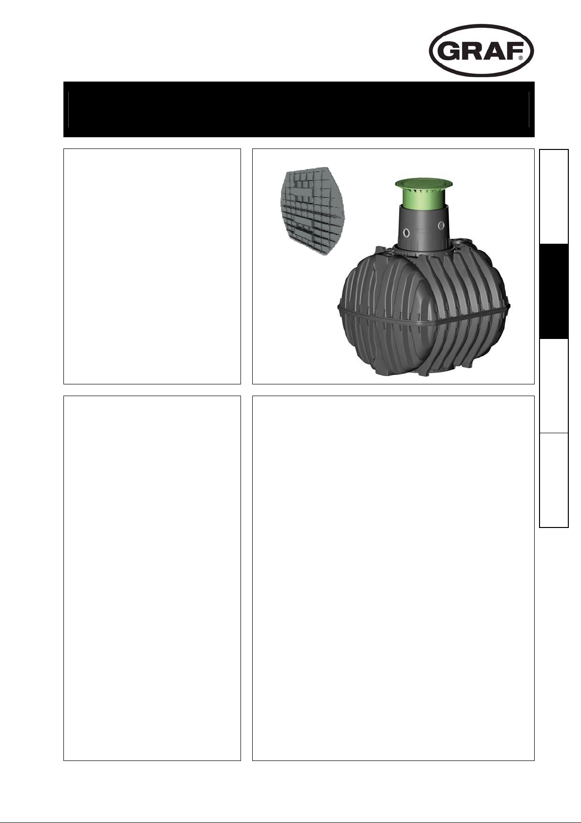
Installation and maintenance instructions for GRAF septic
tanks, Carat series
3750 L
4800 L
6500 L
Order No. 370016
Order No. 370017
Order No. 370018
Deutsch 1
The points described in these
instructions must be observed
under all circumstances. All
warranty rights are invalidated
in the event of non-observance.
Separate installation
instructions are enclosed in the
transportation packaging for all
additional articles purchased
from GRAF.
The tank must be checked for
any damage prior to insertion
into the trench under all
circumstances.
Missing instructions can be
downloaded on www.graf.info or
can be requested from GRAF.
Table of contents
1. GENERAL NOTES 11
1.1 Safety 11
2. INSTALLATION CONDITIONS 12
3. TECHNICAL DATA 13
4. TANK STRUCTURE 14
5. INSTALLATION AND ASSEMBLY 14
5.1 Construction site 15
5.2 Trench 15
5.3 Insertion and filling 16
5.4 Routing connections 16
6. ASSEMBLING THE TANK DOME AND TELESCOPIC
DOME SHAFT 17
6.1 Assembling the tank dome 17
6.2 Assembling the telescopic dome shaft 17
6.3 Telescopic dome shaft on which persons may walk 17
6.4 Telescopic dome shaft over which passenger cars
may drive 17
6.5 Truck telescopic dome shaft 18
6.6 Assembling the adapter 18
English 10
Français 19 Español 28
7. INSPECTION AND SERVICING 18
10 / 36
Page 2

info@graf.info
www.graf.info
1. General notes
1.1 Safety
The relevant accident prevention regulations according to BGV C22 must be observed during all work.
Particularly when walking on the tanks, a 2nd person is required to secure the tank.
The relevant regulations and standards must additionally be taken into consideration during installation,
assembly, servicing, repair, etc. Relevant notes can be found in the corresponding sections of these
instructions.
When entering the tank it is indispensable to empty all chambers. Under no
circumstances one must not enter the container if there is still an unemptied
chamber.
During all work on the system or parts of the system, the entire system must
always be rendered inoperable and secured to prevent unauthorised
reactivation.
Except in the event of work carried out in the tank, the cover of the tank must
always be kept sealed, as this otherwise constitutes a maximum risk of
accident. The rain protection installed on delivery is merely transportation
packaging. It cannot be walked on and is not child-proof; it must be replaced
with a suitable cover immediately following delivery (telescopic dome shaft
with corresponding cover)! Only original GRAF covers or covers approved in
writing by GRAF must be used.
GRAF offers an extensive range of accessories, all of which are designed to
match each other and which can be extended to form complete systems. The use of other accessories
may lead to impediments to the system's functional capability, therefore invalidating liability for resulting
damage.
11 / 36
Page 3
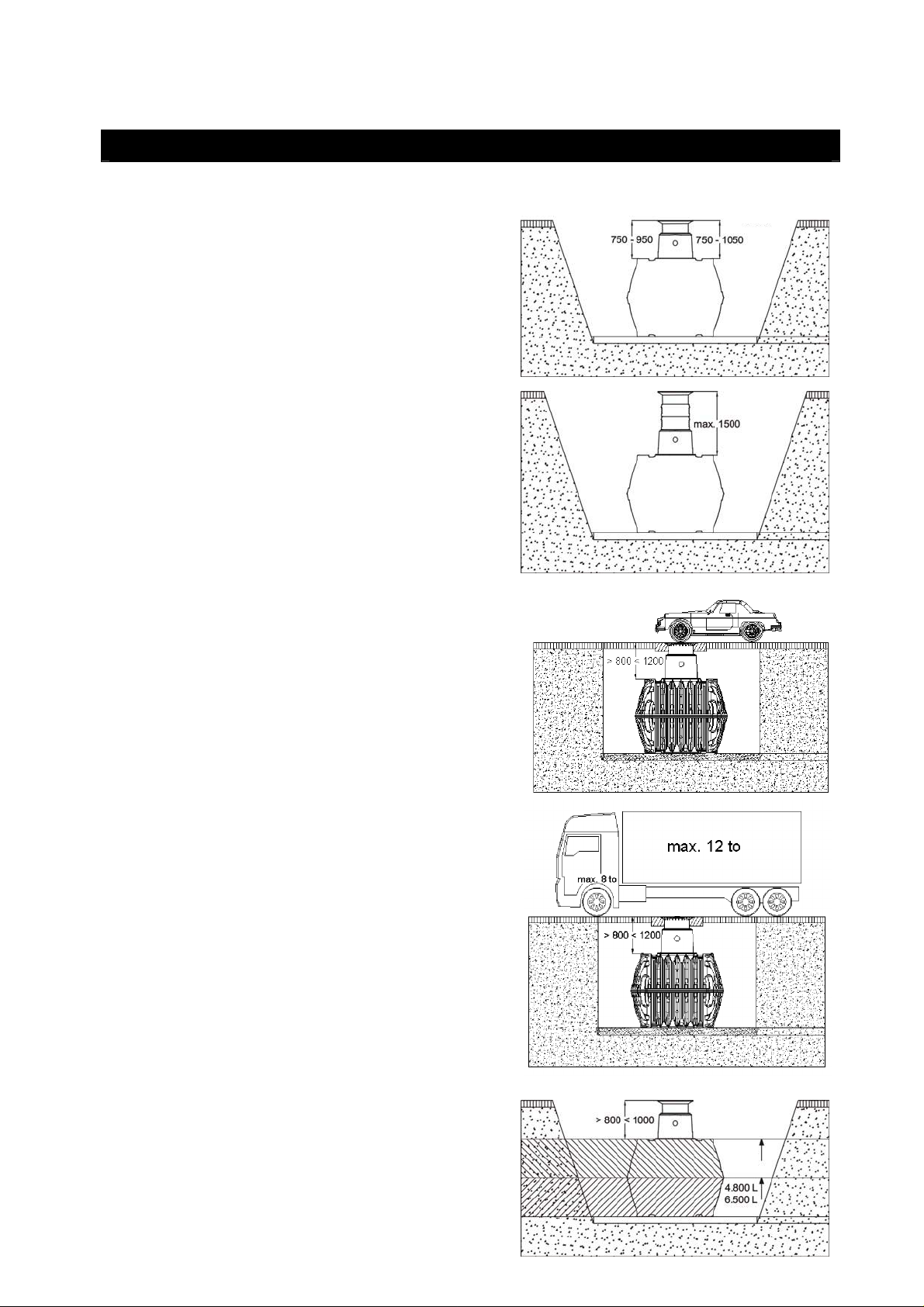
2. Installation conditions
Coverage heights with telescopic dome shaft in
green areas.
The mini dome shaft produces a depth of cover
of between 420 – 620 mm.
Maximum coverage heights with intermediate
section and telescopic dome shaft.
(in green areas only, without groundwater and
stratum water)
info@graf.info
www.graf.info
Mini telescopic
dome shaft
Maxi telescopic dome shaft
+
Telescopic with cast iron lid
Covering heights with cast telescopic dome shaft
(with class B cast cover) in areas with car traffic
(load up to 3.5 t).
Coverage heights with truck telescopic dome
shaft (with cover class D – to be provided at
construction site) in areas used by trucks with a
max. weight of 12 t.
Coverage heights on installation in groundwater
– the hatched areas specify the permissible
immersion depth for the adjacent tank size.
(not under areas used by passenger cars or
trucks)
12 / 36
3.750 L
Page 4

info@graf.info
www.graf.info
3. Technical data
440
200
140
290
Hges
440
Hges
Hges
L
B
with mini tank dome
140
245
355
245
610
Hges
245
520
H
L
B
with tank dome, high version
Tank 3750 litres 4800 litres 6500 litres
Art. No. 370002 370003 370004
Weight
150 kg 185 kg 220 kg
L 2280 mm 2280 mm 2390 mm
W 1755 mm 1985 mm 2190 mm
H 1590 mm 1820 mm 2100 mm
Htot* 2200 mm 2430 mm 2710 mm
Htot*
with mini tank dome
*Htot = total height
1870 mm 2100 mm 2380 mm
13 / 36
Page 5

4. Tank structure
Cover
Telescopic dome shaft (can be inclined by 5°)
Profile seal
Tank dome (can be rotated by 360°)
Tank - tank dome seal
Carat underground tank
Baffle
5. Installation and assembly
Subsoil
Telescopic dome shaft
Compacted foundation
Surrounding (round-grained gravel, max.
grain size 8/16)
1
4
7
info@graf.info
www.graf.info
Covering layer
Carat underground tank
Concrete layer for surfaces used by
passenger cars / trucks
2
1
2
3
4
5
6
ß according to DIN 4124
ß nach DIN 4124
5
7
ß
> 100 mm
< 300 mm
< 300 mm
< 300 mm
< 300 mm
< 300 mm
< 300 mm
< 300 mm
< 300 mm
> 150 mm
14 / 36
6
3
Page 6

info@graf.info
www.graf.info
5. Installation and assembly
5.1 Construction site
Under all circumstances, the following points must be clarified prior to installation:
The structural suitability of the ground according to DIN 18196
Maximum groundwater levels which occur and drainage capability of the subsoil
Types of load which occur, e.g. traffic loads
An expert ground report should be requested from the local planning authority to determine the physical
characteristics of the subsoil.
5.2 Trench
To ensure that sufficient space is available for working, the base area of the trench must exceed the
dimensions of the tank by 500 mm on each side; the distance from solid constructions must be at least
1000 mm.
The embankment must be designed according to DIN 4124. The construction site must be horizontal and
plane and must guarantee sufficient load-bearing capacity.
The depth of the trench must be dimensioned so that the max. earth coverage (see point 2 – installation
conditions) above the tank is not exceeded. To use the system throughout the entire year, it is necessary
to install the tank and those parts of the system which conduct water in the frost-free area. The frost-free
depth is usually approx. 600 mm – 800 mm; precise information in this regard can be obtained from the
responsible authority.
A layer of compacted, round-grain gravel (grain size 8/16, thickness approx. 150 - 200 mm) is applied as
the foundation.
5.2.1 Slope, embankment, etc.
On installation of the tank in the immediate vicinity (< 5 m)
of a slope, earthen mound or slope, a statically calculated
supporting wall must be erected to absorb the soil
pressure. The wall must exceed the dimensions of the
tank by at least 500 mm in all directions, and must be
located at least 1000 mm away from the tank.
5.2.2 Groundwater and cohesive (water-impermeable)
soils (e.g. clay soil)
If it is anticipated that the tanks will be immersed deeper
into the groundwater than is shown in the adjacent figure,
sufficient dissipation must be ensured. (See table for
3.750 L
max. immersion depth).
Dissipation of the drainage water (e.g. via an annular
drainage system) is recommended in the case of
cohesive, water-impermeable soils.
Tank size
3750 L 4800 L 6500 L
Immersion depth
1590 mm 910 mm 1050 mm
5.2.3 Installation adjacent to surfaces used by
vehicles
If the underground tanks are installed adjacent to
surfaces which are used by heavy vehicles weighing over
12 t, the minimum distance away from these surfaces is
at least the depth of the trench.
15 / 36
Page 7

info@graf.info
www.graf.info
5. Installation and assembly
5.2.4 Connection of several tanks
Two or more tanks are connected via the assembly
surfaces by means of GRAF special seals and basic pipes
(to be provided at construction site).
The apertures must be drilled to the corresponding size
using only the GRAF special crown bit. It must be ensured
that the distance between the tanks is at least 600 mm.
The pipes must project at least 200 mm into the tanks.
5.3 Insertion and filling
The tanks must be inserted, impact-free, into the prepared
trench using suitable equipment. The tank is filled with 1/3
water before filling in the tank surrounding.
Afterwards the surrounding (roundgrain gravel, max. grain
size 8/16) is then filled in layers of max. 30 cm steps and
is compacted.
The individual layers must be well-compacted (manuel
tamper). Damage to the tank must be avoided during
compaction. Mechanical compaction machines must not
be used under any circumstances. The surrounding must
be at least 500 mm wide.
5.4 Routing connections
All feed and overflow pipes must be routed with a decline
of at least 1% in the direction of flow (possible,
subsequent settling must be taken into consideration in
this case).
All suction, pressure and control lines must be routed in
an empty pipe, which must be routed as straight as
possible, without bending, to the tank with a decline.
Necessary bends must be formed using 30° moulded
sections.
2. 3/3
>1%
>1%
>1%
1. 1/3
Important: The empty pipe must be connected to an
aperture above the max. water level.
16 / 36
Page 8

info@graf.info
www.graf.info
6. Assembling the tank dome and telescopic dome shaft
6.1 Assembling the tank dome
Prior to assembly, the enclosed seal is inserted into the tank
domes’s groove „B“. The tank dome is then aligned with the
piping connections and is locked to the tank neck. It is essential
to make sure that the upper seal "A" is correctly installed.
„A“ „B“
6.2 Assembling the telescopic dome shaft
The telescopic dome shaft enables infinite adaptation of the
tank to given site surfaces with earth coverage of between
750 mm and 950 mm (Mini telescopic dome shaft) or 750 mm
and 1050 mm (Maxi telescopic dome shaft).
„A“
„B“
For assembly purposes, the enclosed profile seal (material
EPDM) is inserted into the tank dome's sealing groove and is
coated generously with soft soap (do not use mineral oilbased lubricants, as these attack the seal). The telescope is
then greased, inserted and aligned with the surface of the
site.
6.3 Telescopic dome shaft on which persons may walk
Important: To prevent loads from being transferred onto the tank,
round-grain gravel (max. grain size 8/16) is filled in in layers
around the telescope and is evenly compacted. Damage to the
tank dome and telescope must be avoided during this step. The
cover is then positioned and is sealed to prevent entry by children.
Tighten the threaded connection on the cover so tightly that it
cannot be opened by a child!
6.4 Telescopic dome shaft over which passenger cars may drive
If the tank is installed under areas used by passenger cars, the
collar area of the telescope (colour anthracite) must be
supported with concrete (load class B25 = 250 kg/m²). The
layer of concrete to be installed must be at least 300 mm wide and
approx. 200 mm high all around. The minimum coverage above
the shoulder of the tank is at least 800 mm (max. 1050 mm with
telescope, coverage up to max. 1200 mm possible with
intermediate section).
Attention: It is essential to use the cast telescopic dome shaft
(with class B cast cover).
17 / 36
Page 9

info@graf.info
www.graf.info
6. Assembling the tank dome and telescopic dome shaft
6.5 Truck telescopic dome shaft
On installation under areas used by trucks with a maximum
weight of 12 t, the telescope is supported as described in
point 6.2. The concrete rings (Ø 600 mm) and a cast
frame with star-shaped load distribution for mounting the
cast cover are then installed (observe earth coverage of at
least 800 mm, max. 1200 mm). The cast frame must have a
supporting area of approx. 1 m².
Attention: It is essential to use the truck telescope dome
shaft (class D cover to be provided by customer).
6.6 Assembling the adapter
For lager coverage heights a adapter is needed. To insert the
adapter into the tank dome, soft soap is needed. Into the highest
groove of the adapter the profile seal is inserted an greased
generously. Afterwards push the telescopic dome shaft into the
adapter and adapt it to the planned area surface.
max. earth-cover 1500 mm
(in each case in connection with the Maxi telescopic dome shaft)
Telescopic dome shaft (can be inclined by 5°)
Adapter
Tank dome (can be rotated by 360°)
7. Inspection and servicing
The entire system must be checked for leaks, cleanliness and stability at least every three months.
The entire system should be serviced at intervals of approx. 5 years. In this case, all parts of the system
must be cleaned and their function checked. Servicing should be carried out as follows:
All chambers of the tank have to be emptied completely, one must not enter the tank if there is still an
unemptied chamber.
Drain the tank completely
Clean surfaces and internal parts with water
Remove all dirt from the tank
Check that all internal parts are firmly seated.
Otto Graf GmbH – Carl-Zeiss-Str. 2-6 – D-79331 Teningen – Tel.: 0049/(0)7641/589-0 – Fax: 0049/(0)7641/589-50
GRAF SARL – 45, Route d´Ernolsheim – F-67120 Dachstein Gare – Tel.: 0033/388497310 – Fax: 0033/388493280
GRAF Iberica – C/Marquès Caldes de Montbui, 114 baixos – ES-17003 Girona – Tel.: +34/972 913 767 – Fax: +34/972 913 766
GRAF Ltd – Maidstone, Kent – UK-ME16 8Ry – Phone: +44 (0) 16 22 68 65 50
18 / 36
02-2012
Page 10

3750 L
4800 L
6500 L
info@graf.info
www.graf.info
Notice de montage et d’entretien
du collecteur d’eau de pluie GRAF série Carat
N° de réf. 370016
N° de réf. 370017
N° de réf. 370018
Deutsch 1 English 10
Afin de garantir le bon
fonctionnement et la longévité de
votre installation, les différents
points décrits dans cette notice
doivent scrupuleusement être
respectés. Tout manquement à
ces règles annulera
systématiquement la garantie.
Lisez également toutes les
notices des autres éléments
fournis par la société GRAF. Vous
trouverez les notices de montage
jointes dans l’emballage.
Avant de positionner la cuve
dans la fosse, il est important de
vérifier que celle-ci n’a pas été
endommagée.
Les notices manquantes peuvent
être téléchargées sur
www.graf.info ou être demandées
auprès de la société GRAF.
Sommaire
1. GÉNÉRALITÉS 20
1.1 Sécurité 20
2. CONDITIONS DE MISE EN PLACE 21
3. CARACTÉRISTIQUES TECHNIQUES 22
4. ASSEMBLAGE DU RÉSERVOIR 23
5. MISE EN PLACE ET MONTAGE 23
5.1 Support de construction 24
5.2 Fouille 24
5.3 Mise en place et remplissage 25
5.4 Poser les raccords 25
6. MONTER LE DOME DU RESERVOIR ET LA
CHEMINEE-DOME TELESCOPIQUE 26
6.1 Montage du dôme 26
6.2 Monter la cheminée-dôme télescopique 26
6.3 Cheminée-dôme télescopique résistante aux charges
de pas 26
6.4 Cheminée-dôme télescopique résistante aux charges
de roues 26
6.5 Cheminée-dôme télescopique passage camions 27
6.6 Montage de la rallonge 27
7. INSPECTION ET ENTRETIEN 27
Français 19
Español 28
19 / 36
 Loading...